
Related Manuals for JLG Toucan 8e


Summary of Contents for JLG Toucan 8e
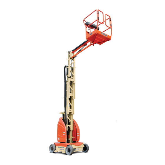
- Page 1 Operation and Safety Manual Original Instructions - Keep this manual with the machine at all times. TOUCAN 8E TOUCAN 20E S/N A300052840 to present 31210162 February 01, 2015 ® English - Operation and Safety...
- Page 3 The purpose of this manual is to provide owners, users, operators, lessors, and lessees with the precautions and operating procedures essential for the safe and proper machine operation for its intended purpose. Due to continuous product improvements, JLG Industries, Inc. reserves the right to make specification changes without prior notification. Contact JLG Industries, Inc. for updated information.
- Page 4 INDICATES INFORMATION OR A COMPANY POLICY THAT RELATES AVOIDED, COULD RESULT IN SERIOUS INJURY OR DEATH. THIS DIRECTLY OR INDIRECTLY TO THE SAFETY OF PERSONNEL OR PRO- DECAL WILL HAVE AN ORANGE BACKGROUND. TECTION OF PROPERTY. – JLG Lift – 31210162...
- Page 5 FOREWORD For: • Accident Reporting • Standards and Regulations THIS PRODUCT MUST COMPLY WITH ALL SAFETY RELATED BULLE- TINS. CONTACT JLG INDUSTRIES, INC. OR THE LOCAL AUTHORIZED Compliance Information • Product Safety Publica- JLG REPRESENTATIVE FOR INFORMATION REGARDING SAFETY- tions •...
- Page 6 FOREWORD REVISION LOG Original Issue - August 03, 2010 Manual Revised - May 15, 2012 Manual Revised - May 13, 2014 Manual Revised - November 03, 2014 Manual Revised - February 01, 2015 – JLG Lift – 31210162...
-
Page 7: Table Of Contents
Pre-Start Inspection ..... 2-4 Grade and Side Slope ....4-3 31210162 – JLG Lift –... - Page 8 Lifting ....... 4-17 Battery Voltage and Electrolyte Specific Gravity . 6-14 – JLG Lift – 31210162...
- Page 9 SECTION - 7 - INSPECTION AND REPAIR LOG Introduction ......6-29 31210162 – JLG Lift –...
- Page 10 Emergency Controls ..... . . 4-10 4-9. Machine Tie-Down ......4-17 – JLG Lift – 31210162...
- Page 11 6-10 Recommended Viscosity Grade....6-26 Inspection and Repair Log ....7-1 31210162 – JLG Lift –...
- Page 12 TABLE OF CONTENTS NOTES: – JLG Lift – 31210162...
-
Page 13: Section 1 - Safety Precautions
• Only authorized and qualified personnel can operate the contact JLG Industries, Inc. (“ JLG”). machine. • Read, understand, and obey all DANGERS, WARNINGS, CAUTIONS, and operating instructions on the machine FAILURE TO COMPLY WITH THE SAFETY PRECAUTIONS LISTED IN and in this manual. -
Page 14: Workplace Inspection
• Do not operate or raise the platform while on trucks, trail- ers, railway cars, floating vessels, scaffolds or other equip- ment unless approved in writing by JLG. MODIFICATION OR ALTERATION OF AN AERIAL WORK PLATFORM • Do not operate the machine in hazardous environments SHALL BE MADE ONLY WITH WRITTEN PERMISSION FROM THE MANU- unless approved for that purpose by JLG. -
Page 15: Operation
• Do not carry materials directly on platform railing. Contact JLG for approved material handling accessories. • When two persons are in the platform, the operator shall be responsible for all machine operations. -
Page 16: Trip And Fall Hazards
“three point contact” with the machine, using two hands and one foot or two feet and one hand during entry and exit. • Before operating the machine, make sure all gates are closed and fastened in their proper position. – JLG Lift– 31210162... -
Page 17: Electrocution Hazards
Minimum Approach Distance (MAD) as shown in Table 1-1. sions of the insulating barrier. This determination shall be • Allow for machine movement and electrical line swaying. 31210162 – JLG Lift –... -
Page 18: Tipping Hazards
• Do not elevate platform or drive with platform elevated while on a sloping, uneven, or soft surface. • Do not raise the platform or drive from an elevated posi- tion unless the machine is on firm, level and smooth sur- faces. – JLG Lift– 31210162... -
Page 19: Crushing And Collision Hazards
• Limit travel speed according to conditions of ground sur- must be removed before attempting to stabilize the face, congestion, visibility, slope, location of personnel, machine. Use cranes, forklift trucks, or other appropriate equipment to stabilize machine. 31210162 – JLG Lift –... -
Page 20: Towing, Lifting, And Hauling
• Never allow personnel in platform while towing, lifting, or hauling. • This machine should not be towed, except in the event of emergency, malfunction, power failure, or loading/unload- ing. Refer to Emergency Towing Procedures Section of this Manual for emergency towing procedures. – JLG Lift– 31210162... -
Page 21: Beaufort Scale (For Reference Only)
32-38 13.9-17.1 Near Gale/Moderate Gale Whole trees in motion. Effort needed to walk against the wind. 39-46 17.2-20.7 Fresh Gale Twigs broken from trees. Cars veer on road. 47-54 20.8-24.4 Strong gale Light structure damage. 31210162 – JLG Lift –... - Page 22 SECTION 1 – SAFETY PRECAUTIONS NOTES: 1-10 – JLG Lift– 31210162...
-
Page 23: Section 2. User Responsibilities, Machine Preparation, And Inspection
4. Use of approved fall protection device. or the job site. 5. Enough knowledge of the mechanical operation of the machine to recognize a malfunction or potential mal- function. 31210162 – JLG Lift –... -
Page 24: Preparation, Inspection, And Maintenance
JLG INDUSTRIES, INC. RECOGNIZES A FACTORY-TRAINED SERVICE TECHNICIAN AS A PERSON WHO HAS SUCCESSFULLY COMPLETED THE JLG SERVICE TRAINING SCHOOL FOR THE SPECIFIC JLG PRODUCT MODEL. – JLG Lift – 31210162... -
Page 25: Inspection And Maintenance Table
At intervals as specified in the Service and Owner, Dealer or User Qualified JLG Mechanic Service and Maintenance Manual Maintenance Maintenance Manual. NOTE: Inspection forms are available from JLG. Use the Service and Maintenance Manual to perform inspections. 31210162 – JLG Lift –... -
Page 26: Pre-Start Inspection
4. Operation and Safety Manuals – Make sure a copy of the Operator and Safety manual, AEM Safety Manual (ANSI markets only), and ANSI Manual of Responsibili- ties (ANSI markets only) is enclosed in the weather resistant storage container. – JLG Lift – 31210162... - Page 27 SECTION 2 – USER RESPONSIBILITIES, MACHINE PREPARATION, AND INSPECTION Figure 2-1. Daily Walk-Around Inspection 31210162 – JLG Lift –...
-
Page 28: General
2. Platform & Ground Control Consoles - Placards installed and fastened. See inspection note. secure and legible, control levers and switches return to neutral and emergency stop switches function properly. 3. Steering Assembly - See inspection note. – JLG Lift – 31210162... -
Page 29: Function Check
Figure 3-4). the drive orientation system (DOS) indicator lights up (Yellow). Actuate a drive function: the drive function is dis- abled. The DOS indicator blinks and the DOS over- 31210162 – JLG Lift –... -
Page 30: Tilt Sensor Check
Confirm an audible alarm sounds. b. Verify the tilt indicator (red) blinks. c. Check that the following functions are affected : - Drive function disabled. - Mast/Jib lift-up and swinging movements can be performed only in creep mode. – JLG Lift – 31210162... -
Page 31: Overload Sensor Check (If Equipped)
Verify the overload indicator (Red) blinks. c. Check that all functions are disabled. 2. From the Ground Control Panel: a. Confirm an audible alarm sounds. b. Verify the overload indicator (Red) blinks. Figure 2-3. Overload Sensor 31210162 – JLG Lift –... -
Page 32: Slack/Broken Chain Sensors Check
Confirm an audible alarm sounds. b. Check when the slack chain indicator warning is activated, the following functions are disabled: - Mast/Jib lower - Swing c. Repeat check for each chain sensor Figure 2-4. Slack/Broken Chain Sensors 2-10 – JLG Lift – 31210162... -
Page 33: Gate Sensors Check (Xl Basket Only)
1. From the Platform Control Console: a. Ensure the gate open warning light is illuminated. b. Check that all functions are disabled. 2. From the Ground Control Console: a. Check that all functions are disabled. Figure 2-5. XL Basket 31210162 – JLG Lift – 2-11... - Page 34 SECTION 2 – USER RESPONSIBILITIES, MACHINE PREPARATION, AND INSPECTION NOTES: 2-12 – JLG Lift – 31210162...
-
Page 35: Section 3 - Machine Controls And Indicators
Swinging motor release valve (see figure 3-5) Control valves 9- Platform Control console Manual swinging operating device Counterweight 10- Manual Storage Container (see figure 3-6) 11- Access door to battery Figure 3-1. Basic Nomenclature - Location of Machine Controls 31210162 – JLG Lift –... -
Page 36: General
THE EMERGENCY STOP SWITCHES MUST BE POSITIONED TO OFF TO PREVENT DRAINING THE BATTERIES. TO AVOID SERIOUS INJURY, DO NOT OPERATE MACHINE IF ANY CON- TROL LEVERS OR TOGGLE SWITCHES CONTROLLING PLATFORM MOVEMENT DO NOT RETURN TO THE OFF POSITION WHEN RELEASED. – JLG Lift – 31210162... -
Page 37: Ground Control Station
6. Battery Charger Status Indicators (depending on equipment) 7. Emergency Stop Switch 8. Function Enable Button 9. Mast Lift/Lower Buttons 10. Jib Lift/Lower Buttons 11. Superstructure Swing Buttons 12. Brake Release Button Figure 3-2. Ground Control Station 31210162 – JLG Lift –... - Page 38 The last bar flashes when the level of charge is less than 10%. The bar-graph is not displayed when the batteries are completely discharged. – JLG Lift – 31210162...
- Page 39 Platform/Off/Ground selector switch to operate the all functions of the machine. The switch must be turned brake release switch. Refer to section 4-13 of this manual for clockwise to restore the machine functions. further information. 31210162 – JLG Lift –...
-
Page 40: Platform Manual Descent Valves
KEEP BODY, HANDS AND ARMS OUT OF THE PATH OF THE MAST, THE JIB AND THE PLATFORM WHILE LOWERING. Figure 3-3. Mast Manual Descent Valve – JLG Lift – 31210162... -
Page 41: Jib Manual Descent Valve
SECTION 3 – MACHINE CONTROLS AND INDICATORS Jib Manual Descent Valve - The jib manual descent button is located on the jib cylinder valve. Figure 3-4. Jib Manual Descent Valve 31210162 – JLG Lift –... -
Page 42: Manual Swinging Operating Devices
Those devices are composed of: - a rotary valve (1) located on the pump/motor control valves assembly to release the swinging motor (Refer to Figure 3-5.). Figure 3-6. Solid Hand Wheel Figure 3-5. Rotary Valve – JLG Lift – 31210162... -
Page 43: Platform Control Station
5. When finished swinging, fully close the rotary valve, close the access cover and reposition the access cover to the pump/motor assembly. 31210162 – JLG Lift –... - Page 44 4. Drive/Swing Functions Controller 5. Steer Switch 6. Mast/Jib Function Enable Button 7. Mast Lift Up/Down Joystick Controller 8. Jib Lift Up/Down Joystick Controller 9. Drive Orientation System (DOS) Override Button 10. Horn Button 3-10 – JLG Lift – 31210162...
-
Page 45: Platform Control Indicator Panel
Tilt Indicator Warning Light f- Overload Indicator Warning Light (if equipped) g- Slack Chain Indicator Warning Light h- Battery Discharge Indicator (BDI) i- Soft Touch Indicator (If equipped) j- Opening Gate Warning Light (XL Basket Only) 31210162 – JLG Lift – 3-11... - Page 46 (refer to machine specifications for max. allowable slope angle). If the mast is out of the transport (stowed) posi- tion and the chassis is out of level, an audible alarm will sound. 3-12 – JLG Lift – 31210162...
- Page 47 5. Steer Switch - The thumb-operated steer switch on top of the control handle activates the steer wheels in the direction activated (right or left). 31210162 – JLG Lift – 3-13...
- Page 48 10. Horn - This button, when activated, permits the operator to warn job site personnel when the machine is operat- ing in the area. 3-14 – JLG Lift – 31210162...
-
Page 49: Decal Installation
SECTION 3 – MACHINE CONTROLS AND INDICATORS DECAL INSTALLATION Figure 3-8. Decal Installation - Sheet 1 31210162 – JLG Lift – 3-15... - Page 50 SECTION 3 – MACHINE CONTROLS AND INDICATORS Figure 3-9. Decal Installation - Sheet 2 3-16 – JLG Lift – 31210162...
- Page 51 SECTION 3 – MACHINE CONTROLS AND INDICATORS Figure 3-10. Decal Installation - Sheet 3 31210162 – JLG Lift – 3-17...
- Page 52 AU2098 AU2098 AU2098 AU2119 AU2119 AU2152 AU2102 AU2120 AU2120 AU2120 AU2164 AU2117 AU2117 AU2154 AU2103 AU2118 AU2118 AU2118 AU2155 AU2210 AU2210 AU2210 AU2210 AU2210 AU2104 AU2104 AU2104 AU2104 AU2104 AU2215 AU2215 AU2215 AU2215 AU2215 3-18 – JLG Lift – 31210162...
- Page 53 SECTION 3 – MACHINE CONTROLS AND INDICATORS Table 3-1. 8E & 20E - Decal Installation Element Element ANSI Spanish Portuguese ANSI Spanish Portuguese AU2228 AU2228 AU2228 AU2228 AU2206 AU2206 AU2206 AU2206 AU2229 AU2229 AU2229 AU2229 AU2229 31210162 – JLG Lift – 3-19...
- Page 54 SECTION 3 – MACHINE CONTROLS AND INDICATORS NOTES: 3-20 – JLG Lift – 31210162...
-
Page 55: Section 4. Machine Operation
The machine has a Ground Control Sta- tion which will override the Platform Control Station. Ground 4. Machine is as originally equipped from JLG. Controls operate mast and jib lift and swing and are to be used... -
Page 56: Position Of Least Backward Stability
SECTION 4 – MACHINE OPERATION Figure 4-2. Position of Least FORWARD stability Figure 4-1. Position of Least BACKWARD stability – JLG Lift – 31210162... -
Page 57: Grade And Side Slope
Refer to Table 6-1. With the mast out of transport (stowed) position, the machine must not be operated on grade or side slopes greater than that is specified in Table 6-1. 31210162 – JLG Lift –... -
Page 58: Grade And Side Slope
SECTION 4 – MACHINE OPERATION Figure 4-3. Grade and Side Slope – JLG Lift – 31210162... -
Page 59: Operation
MENT DOES NOT RETURN TO THE OFF OR NEUTRAL POSITION WHEN RELEASED. IF THE PLATFORM DOES NOT STOP WHEN CONTROL LEVER OR THE ENABLE BUTTON/TRIGGER SWITCH IS RELEASED, USE THE EMER- GENCY STOP SWITCH TO STOP THE MACHINE. 31210162 – JLG Lift –... -
Page 60: Steering
3. Return the controller to its centered (neutral) position to stop, then release the trigger. IF THE TILT INDICATOR WARNING LIGHT/ALARM IS ACTIVATED WHILE DRIVING WITH THE MAST RAISED, LOWER THE MAST COMPLETELY AND DRIVE TO A SMOOTH, FIRM AND LEVEL SURFACE. – JLG Lift – 31210162... -
Page 61: Drive Orientation System (Dos)
(3). Move the drive control joystick in a direction matching the directional arrow, for the intended direction of travel. Figure 4-6. Lift Controls Figure 4-5. Drive Orientation System (DOS) 31210162 – JLG Lift –... -
Page 62: Raising And Lowering The Mast
5. Return the controller to its centered (neutral) position to 5. Return the controller to its centered (neutral) position to stop, then release the enable button. stop, then release the enable button. – JLG Lift – 31210162... -
Page 63: Swinging
3. Return the controller to its centered (neutral) position to stop, then release the trigger. WHEN SWINGING, MAKE SURE THERE IS AMPLE ROOM FOR THE JIB TO CLEAR SURROUNDING WALLS, PARTITIONS AND EQUIPMENT. Figure 4-7. Swing Control 31210162 – JLG Lift –... -
Page 64: Emergency Control
1. Position the key-select switch (1) to GROUND. 2. Push and hold the enable button (2). 3. Actuate the appropriate function button (3) until the desired elevation or position of the platform is achieved. Figure 4-8. Emergency Controls 4-10 – JLG Lift – 31210162... -
Page 65: Alarms
LOWER THE MAST AND REPOSITION MACHINE SO THAT IT IS LEVEL BEFORE ELEVATING THE MAST. When the tilt indicator warning is activated, the following func- tions are affected: -The Drive function is disabled out of stowed position. 31210162 – JLG Lift – 4-11... -
Page 66: Slack Chain Warning Light/Alarm
- A foreign body entering the guiding system. - A lack of lubrication (see Section 6). - An incorrect mast adjustment (see the Service Manual). 4-12 – JLG Lift – 31210162... -
Page 67: Gate Opening Warning Light (Xl Basket Only)
Emergency Platform Retrieval only. SIDE GATES MUST NOT BE USED AS A MEANS FOR ACCESS TO AND Refer to Section 5-6, Machine Safety System Override (MSSO) EGRESS FROM THE PLATFORM. for operating procedures. 31210162 – JLG Lift – 4-13... -
Page 68: Shut Down And Park
NOTE: It is not necessary to charge the battery if the electrolyte specific gravity has not dropped under 1.240kg/l. Doing so regularly, will greatly reduce battery life. The battery charger AC input plug (1) is located on the battery compartment. 4-14 – JLG Lift – 31210162... - Page 69 NOTE: If the charger is left plugged in, the charger will automati- cally restart a complete charge cycle if the batteries volt- age drops below a minimum voltage or 30 days has elapsed. 31210162 – JLG Lift – 4-15...
-
Page 70: Battery Charger Fault Code
30 seconds of operation. Once it has been determined that the batteries and connections Fault are not faulty and fault 6 is again displayed after interrupting AC power for at least 10 seconds, the charger must be brought to a qualified service depot. 4-16 – JLG Lift – 31210162... -
Page 71: Tie-Down/Lift Lugs
- Attach lifting straps/chains at BOTH lifting lugs as shown in - Machine must be tied down to the truck bed or trailer deck as Figure 4-10. shown in Figure 4-9. Figure 4-10. Lifting the Machine Figure 4-9. Machine Tie-Down 31210162 – JLG Lift – 4-17... -
Page 72: Towing
WHEN DRIVING THE FORK TRUCK, KEEP THE WORK PLATFORM AS NEAR TO THE GROUND AS POSSIBLE (BUT WITH A SUFFICIENT CLEAR- ANCE FOR THE WHEELS NOT TO CONTACT THE GROUND). Figure 4-11. Lifting the Machine Using a Fork Truck 4-18 – JLG Lift – 31210162... -
Page 73: Electric Brake Release
NOTE: Any action to remove electrical power from the brakes such as, depressing the ground control emergency stop switch, or switching the key switch to OFF or PLATFORM MODE will re-engage the brakes. Figure 4-12. Electric Brake Release 31210162 – JLG Lift – 4-19... - Page 74 SECTION 4 – MACHINE OPERATION NOTES: 4-20 – JLG Lift – 31210162...
-
Page 75: Section 5 - Emergency Procedures
REQUIRED, AND THAT ALL CONTROLS ARE OPERATING CORRECTLY. JLG Industries, Inc. must be notified immediately of any inci- dent involving a JLG product. Even if no injury or property EMERGENCY OPERATION damage is evident, the factory should be contacted by tele- phone and provided with all necessary details. -
Page 76: Platform Or Jib Caught Overhead
Platform or Jib Caught Overhead NOTE: If the MSSO functionality is used, the fault indicator will flash and a fault code is set in the JLG Control System If the platform or the jib become jammed or snagged in over-... -
Page 77: Section 6. General Specifications & Operator Maintenance
Preventive Maintenance and Inspection Schedule included in the Service and Maintenance Manual. Other Publications Available Service and Maintenance Manual....31210090 Illustrated Parts Manual........31210111 Hydraulic Schematic .......... FL0154 Electrical Schematic - Without MSSO ....ELE251 Electrical Schematic - With MSSO.....ELE259 31210162 – JLG Lift –... -
Page 78: Operating Specifications
SECTION 6 – GENERAL SPECIFICATIONS & OPERATOR MAINTENANCE OPERATING SPECIFICATIONS Table 6-1. Operating Specifications And Dimensions Model TOUCAN 8E (CE) TOUCAN 8E XL (CE) TOUCAN 20E (ANSI) Maximum Work Load 200 kg (2 persons + 40 kg material) 500 lbs (227 kg) - Page 79 SECTION 6 – GENERAL SPECIFICATIONS & OPERATOR MAINTENANCE Table 6-1. Operating Specifications And Dimensions Model TOUCAN 8E (CE) TOUCAN 8E XL (CE) TOUCAN 20E (ANSI) Maximum Hydraulic Pressure 16 MPa 2320 psi (16 Mpa) Maximum Ground Bearing Pressure 18.2 kg/cm²...
- Page 80 SECTION 6 – GENERAL SPECIFICATIONS & OPERATOR MAINTENANCE – JLG Lift – 31210162...
- Page 81 SECTION 6 – GENERAL SPECIFICATIONS & OPERATOR MAINTENANCE 31210162 – JLG Lift –...
-
Page 82: Tires Specifications
3.25’ (0.99 m) Overall Machine Length 2.09 m 2.35 m 6.85’ (2.09 m) Platform Size - Length 0.85 m 1.10 m 2.79’ (0.85 m) Platform Size - Width 0.90 m 0.91 m 2.95’ (0.90 m) – JLG Lift – 31210162... -
Page 83: Drive Motors - Hydraulic Power Unit
9.6 l/mn @ 13 MPa Hydraulic Power Unit Flow Rate (2.5 gpm@1885 psi) 6 l (5.5 l usable) Tank (1.6 gal (1.45 gal)) Capacity Hydraulic System (1) Approx. 9 l (2.4 gal) (1) - Including Tank 31210162 – JLG Lift –... -
Page 84: Battery Specifications
SECTION 6 – GENERAL SPECIFICATIONS & OPERATOR MAINTENANCE NOTE: Aside from JLG recommendations, it is not advisable to mix oils of different brands or types, as they may not con- Table 6-5. Battery Specifications tain the same required additives or be of comparable vis- cosities. -
Page 85: Hydraulic Oil Specifications - Optional
198 cSt Cinematic Viscosity @ +40°C (104°F) 30.6 cSt 32.3 cSt 31 cSt Pour Point, Max. -58°C (-72.4°F) -39°C (-38.2°F) -60°C (-76°F) Flash Point, Min. 240°C (464°F) 208°C (406.4°F) 230°C (446°F) Viscosity Index ISO 6743-4 Classification 31210162 – JLG Lift –... -
Page 86: Operator Maintenance
4. Overload System Spring Washer (if equipped) 5. Turntable Bearing Lubrication 6. Telescopic Mast Lubrication 7. Lifting Chain Lubrication 8. Overload System Verification (if equipped) 9. Tilt Sensor Verification Figure 6-3. Operator Maintenance & Lubrication Diagram 6-10 – JLG Lift – 31210162... -
Page 87: Chassis Hood Removal
(1) by approx. 20 mm (1”), then lift the cover to remove it completely; - Remove the right chassis cover (c) : Proceed as for the left cover. Figure 6-4. Chassis Hood Removal 31210162 – JLG Lift – 6-11... -
Page 88: Battery Maintenance
ONLY IN A WELL VENTILATED AREA. Figure 6-5. Level Indicators Add distilled water only when required. ADD ONLY DISTILLED WATER TO BATTERIES. FILL BATTERIES ONLY AFTER CHARGING (DURING CHARGE, ELECTROLYTE LEVEL INCREASES AND CAN OVERFLOW). 6-12 – JLG Lift – 31210162... -
Page 89: Adding Water To Batteries
NOT COMES INTO CONTACT WITH SKIN OR CLOTHING. WEAR PRO- TECTIVE CLOTHING AND EYEWEAR WHEN WORKING WITH BATTER- IES. NEUTRALIZE ANY BATTERY ACID SPILLS WITH BAKING SODA AND WATER. Figure 6-6. Adding Water to Batteries 31210162 – JLG Lift – 6-13... -
Page 90: Battery Voltage And Electrolyte Specific Gravity
- Measure the cell voltage and record the value in the bat- 2. Plunger tery service log. 3. Bulb - Repeat operation for each cell in sequence from B+ (Red Cable) to B- (Blue cable). 6-14 – JLG Lift – 31210162... -
Page 91: Measuring Electrolyte Specific Gravity
SECTION 6 – GENERAL SPECIFICATIONS & OPERATOR MAINTENANCE NOTE: If important disparities are noticed between gravity/volt- age of different cells or if the gravity values are lower than 1.240kg/l (after a complete charge) contact JLG Product Support. Figure 6-8. Measuring Electrolyte Specific Gravity 31210162 –... -
Page 92: Filling System Maintenance
Low temperatures decrease battery capacity. The battery must FOR A LONG PERIOD OF TIME, CHARGE THE BATTERY AND CHECK be fully charged when the machine is operated in a cold envi- ELECTROLYTE LEVEL IN THE CELLS. ronment. 6-16 – JLG Lift – 31210162... -
Page 93: Battery Troubleshooting
SECTION 6 – GENERAL SPECIFICATIONS & OPERATOR MAINTENANCE Battery Troubleshooting 31210162 – JLG Lift – 6-17... -
Page 94: Oil Level/Oil Filter
- wipe all dirt and debris from the filler/breather cap (4) area, add proper grade of oil by using a funnel. Fill until Figure 6-9. Hydraulic Oil Check oil level is between the MIN and MAX markings (3). 6-18 – JLG Lift – 31210162... -
Page 95: Hydraulic Filter Replacement
SECTION 6 – GENERAL SPECIFICATIONS & OPERATOR MAINTENANCE Hydraulic Filter Replacement Lube Point - Replaceable Element (JLG P/N: 930134) Interval - After first 50 hours of operation and every 250 hours thereafter. 1. Turn machine power off at ground control station. -
Page 96: Tires & Wheels
PROPER TORQUE TO PREVENT LOOSE WHEELS, BROKEN LUG NUTS, Figure 6-11. Wheel Lug Nut Tightening Sequence AND POSSIBLE SEPARATION OF WHEEL FROM THE AXLE. BE SURE TO USE ONLY THE LUG NUTS THAT MATCH TO THE CONE ANGLE OF THE WHEEL. 6-20 – JLG Lift – 31210162... -
Page 97: Lubrication
(18-25 ft.lbs) (51-61 ft.lbs) (88-103 ft.lbs) 4. Wheel lug nuts should be torqued after the first 50 hours of operation and after each wheel removal. Check torque every 3 month or 125 hours of operation. 31210162 – JLG Lift – 6-21... -
Page 98: Overload System Spring Washer (If Equipped)
Coat the spring washers using a brush or by spraying. Lube Points - Spring Washers Capacity: A/R Lube - D (See Table 6-6) Interval - Every 125 hours of operation or after each cleaning. Figure 6-12. Overload System Spring Washer Lubrication 6-22 – JLG Lift – 31210162... -
Page 99: Swing Bearing Race
4. Swing the structure to the right to gain access to the first grease fitting (2). 5. Lubricate using a grease gun. 6. Swing the structure 180° to the left to gain access to the second grease fitting and lubricate. Figure 6-13. Swing Bearing Race Lubrication 31210162 – JLG Lift – 6-23... -
Page 100: Swing Bearing Teeth
2. From ground control station, raise the mast to gain access to the turntable plate. 3. Remove bearing teeth covers (1). 4. Apply grease on teeth using a brush (2). Figure 6-14. Swing Bearing Teeth lubrication 6-24 – JLG Lift – 31210162... -
Page 101: Mast Profiles Races
2. Clean the inside walls of the mast profiles to remove the old grease. 3. Using a brush, lubricate the bronze spacer track. 4. Cycle the mast and complete lubrication as necessary. Figure 6-15. Mast Profiles Races Lubrication 31210162 – JLG Lift – 6-25... -
Page 102: Lifting Chains
Table 6-10. Recommended Viscosity Grade TEMPERATURE ISO VISCOSITY GRADE -15°C to 0°C (5°F to 32°F) 15 to 32 mm²/s (cSt) 0°C to 50°C (32°F to 122°F) 46 to 150 mm²/s (cSt) 6-26 – JLG Lift – 31210162... -
Page 103: Overload System Verification (If Equipped)
- Alarms stop. 5. If the overload warning is not activated after the addition of 30kg, have the overload system calibrated by a quali- fied technician before replacing machine into service. Figure 6-16. Overload System Verification 31210162 – JLG Lift – 6-27... -
Page 104: Tilt Sensor Verification
Table 6-1. 6. If the tilt warning is not activated within the indicated angle values, the tilt sensor must be recalibrated by a qualified technician before replacing machine into ser- vice. Figure 6-17. Jacking Points 6-28 – JLG Lift – 31210162... -
Page 105: Dtc Index
9-9 Hardware ........6-52 switch. 31210162 – JLG Lift – 6-29... -
Page 106: Dtc Check Tables
• Normal operation should resume after a power cycle. SYSTEM POWERED DOWN enters a low-power state to preserve battery Refer problem to a qualified JLG mechanic. charge. Displays on the analyzer only; the MDI’s LED is blinking with the display Off. -
Page 107: Power-Up
• Check if the joystick is obstructed or jammed. • Check if the enable switch is damaged. Refer problem to a qualified JLG mechanic. DRIVE PREVENTED - TILTED & Drive is prevented while the platform is not in •... -
Page 108: Platform Controls
• Check if the horn switch is damaged, obstructed or PERMANENTLY SELECTED platform mode. jammed. Refer problem to a qualified JLG mechanic. FUNCTION PROBLEM - STEER The Steer Left Switch was closed during power- • Check if the steer left switch is obstructed or jammed. - Page 109 The trigger switch was closed during power-up in • Check if the trigger switch is obstructed or jammed. TRIGGER PERMANENTLY platform mode. Refer problem to a qualified JLG mechanic. CLOSED TRIGGER CLOSED TOO LONG The trigger switch was closed for more than •...
-
Page 110: Ground Controls
• Check if the concerned switch is damaged, obstructed RELEASE PERMANENTLY power-up in ground mode. or jammed. SELECTED Refer problem to a qualified JLG mechanic. FUNCTION PROBLEM - The Ground Enable Switch was closed during • Check if the concerned switch is damaged, obstructed 2310 GROUND ENABLE power-up in ground mode. - Page 111 2372 LEFT PERMANENTLY up in ground mode. or jammed. SELECTED Refer problem to a qualified JLG mechanic. FUNCTION PROBLEM - SWING The Swing Right Switch was closed during • Check if the concerned switch is damaged, obstructed 2373 RIGHT PERMANENTLY power-up in ground mode.
-
Page 112: Function Prevented
2379 NOT RESPONDING change while raising the mast. aged, obstructed or jammed. Refer problem to a qualified JLG mechanic. MAIN MAST LIMIT SWITCH - A problem has been detected in this function. Refer problem to a qualified JLG mechanic. 2380... - Page 113 • Check if the charger is connected to off board power 2538 CHARGER CONNECTED charging. source and disconnect if desired. Refer problem to a qualified JLG mechanic. FUNCTION PREVENTED - Manual brake release mode is activated. Drive or • Push manual brake release switch again or cycle 2542 BRAKES ELECTRONICALLY lift is not possible.
-
Page 114: Line Contactor Open Circuit
FAULT MESSAGE DESCRIPTION CHECK OPEN CIRCUIT LINE There is a problem with the line contactor. Refer problem to a qualified JLG mechanic. CONTACTOR CONTACTOR DRIVER There is a problem with the power module line Refer problem to a qualified JLG mechanic. -
Page 115: Ground Output Driver
FAULT MESSAGE DESCRIPTION CHECK LEFT BRAKE - SHORT TO A problem has been detected in this function. Refer problem to a qualified JLG mechanic. 3312 BATTERY RIGHT BRAKE - SHORT TO A problem has been detected in this function. Refer problem to a qualified JLG mechanic. - Page 116 FAULT MESSAGE DESCRIPTION CHECK JIB LIFT DOWN VALVE - SHORT A problem has been detected in this function. Refer problem to a qualified JLG mechanic. 33105 TO BATTERY LEFT BRAKE - SHORT TO A problem has been detected in this function.
- Page 117 FAULT MESSAGE DESCRIPTION CHECK PROPORTIONAL RELIEF A problem has been detected in this function. Refer problem to a qualified JLG mechanic. 33367 VALVE - SHORT TO GROUND PROPORTIONAL RELIEF A problem has been detected in this function. Refer problem to a qualified JLG mechanic.
-
Page 118: Thermal Limit
FAULT MESSAGE DESCRIPTION CHECK OVERLOAD LIGHT - SHORT TO A problem has been detected in this function. Refer problem to a qualified JLG mechanic. 33387 GROUND OVERLOAD LIGHT - OPEN A problem has been detected in this function. Refer problem to a qualified JLG mechanic. - Page 119 FAULT MESSAGE DESCRIPTION CHECK SLAVE MODULE The Slave Module (left controller) temperature Refer problem to a qualified JLG mechanic. TEMPERATURE - OUT OF sensor is out of the permitted range. RANGE MASTER MODULE TOO HOT - The Master Module (right controller) has reached •...
-
Page 120: Battery Supply
SECTION 6 – GENERAL SPECIFICATIONS & OPERATOR MAINTENANCE FAULT MESSAGE DESCRIPTION CHECK LEFT DRIVE MOTOR A problem has been detected in this function. Refer problem to a qualified JLG mechanic. 4213 TEMPERATURE - OUT OF RANGE 4-4 Battery Supply FAULT MESSAGE... - Page 121 • Check for damaged batteries, battery cables or con- nections. • Check battery charger function. Be sure to observe indicators for at least 30 seconds. Refer problem to a qualified JLG mechanic. MASTER MODULE VOLTAGE A problem has been detected with the batteries or • Recharge batteries.
-
Page 122: Transmission And Drive System
• Check for damaged batteries, battery cables or con- nections. • Check battery charger function. Be sure to observe indicators for at least 30 seconds. Refer problem to a qualified JLG mechanic. 4-6 Transmission and Drive System FAULT MESSAGE DESCRIPTION... -
Page 123: Communication
FAULT MESSAGE DESCRIPTION CHECK CANBUS FAILURE - MASTER The control system failed to receive messages Refer problem to a qualified JLG mechanic. 6632 MODULE from the Master Module (right controller). CANBUS FAILURE - SLAVE The control system failed to receive messages Refer problem to a qualified JLG mechanic. -
Page 124: Electric Motor
7-7 Electric Motor FAULT MESSAGE DESCRIPTION CHECK MASTER MODULE CAPACITOR There is a problem with the Master Module (right Refer problem to a qualified JLG mechanic. 7721 BANK FAULT controller). SLAVE MODULE CAPACITOR There is a problem with the Slave Module (left Refer problem to a qualified JLG mechanic. -
Page 125: Tilt Sensor
FAULT MESSAGE DESCRIPTION CHECK LEFT MOTOR OUTPUT-OUT OF The left motor voltage output is lower than Refer problem to a qualified JLG mechanic. 7729 RANGE LOW expected (Slave Module). PUMP MOTOR OUTPUT-OUT The pump motor voltage output is higher than Refer problem to a qualified JLG mechanic. -
Page 126: Platform Load Sense
8-2 Platform Load Sense FAULT MESSAGE DESCRIPTION CHECK LSS HAS NOT BEEN The Load Sensing System has not been cali- Refer problem to a qualified JLG mechanic. CALIBRATED brated. FUNCTIONS CUTOUT - The platform is overloaded and functions are • Unload the platform. -
Page 127: Safety System Override
• Check the steer sensor for damage. 8666 • Check that the steer sensor is securely mounted. Refer problem to a qualified JLG mechanic. STEER SENSOR - NOT Invalid signal from the steer sensor. • Check the steer sensor for damage. -
Page 128: Hardware
• Cycle power to clear the fault. 9992 FAILURE (right controller). Refer problem to a qualified JLG mechanic. SLAVE MODULE A/D FAILURE There is an internal error in the Slave Module (left • Cycle power to clear the fault. 9993 controller). - Page 129 • Cycle power to clear the fault. 99100 CHECK POWER CIRCUITS OR Module (right controller) has been detected. Refer problem to a qualified JLG mechanic. MOSFET SHORT CIRCUIT SLAVE MODULE FAILURE - A short circuit on the power outputs of the Slave •...
- Page 130 • Cycle power to clear the fault. 99108 ERROR (right controller). Refer problem to a qualified JLG mechanic. SLAVE MODULE - INTERNAL There is an internal error in the Slave Module (left • Cycle power to clear the fault. 99109 ERROR controller).
- Page 131 • Cycle power to clear the fault. 99118 ERROR (right controller). Refer problem to a qualified JLG mechanic. SLAVE MODULE - INTERNAL There is an internal error in the Slave Module (left • Cycle power to clear the fault. 99119 ERROR controller).
- Page 132 There is an internal error in the Master Module • Cycle power to clear the fault. 99127 ERROR (right controller). Refer problem to a qualified JLG mechanic. MASTER MODULE - INTERNAL There is an internal error in the Master Module • Cycle power to clear the fault. 99128 ERROR (right controller).
-
Page 133: Section 7 - Inspection And Repair Log
SECTION 7 – INSPECTION AND REPAIR LOG SECTION 7. INSPECTION AND REPAIR LOG Type of machine: ________________________________________ Machine Serial Number: __________________________________ Table 7-1. Inspection and Repair Log Date Comments 31210162 – JLG Lift –... -
Page 134: Inspection And Repair Log
SECTION 7 – INSPECTION AND REPAIR LOG Table 7-1. Inspection and Repair Log Date Comments Name: ______________________________________________ Signature: _____________________________________________ – JLG Lift – 31210162... - Page 136 1 JLG Drive McConnellsburg PA. 17233-9533 (717) 485-5161 (717) 485-6417 JLG Worldwide Locations JLG Industries (Australia) JLG Latino Americana Ltda. JLG Industries (UK) Ltd JLG France SAS P.O. Box 5119 Rua Eng. Carlos Stevenson, Bentley House Z.I. Guillaume mon Amy...
Need help?
Do you have a question about the Toucan 8e and is the answer not in the manual?
Questions and answers