Advertisement
Quick Links
Advertisement

Related Manuals for Hunter Metro FAN24211METBN

Summary of Contents for Hunter Metro FAN24211METBN
- Page 1 44214 03/28/2008...
- Page 2 Introduction and Preparation ..........................................................3 Tool and Hardware Legend ............................................................9 Installation ..................................................................15 Operation and Troubleshooting ........................................................41 Introducción y preparación .............................................................3 Leyenda de herramientas y materiales .......................................................9 Instalación ..................................................................15 Operación y localización de fallas ........................................................41 Einleitung und Vorbereitung ...........................................................3 Werkzeug- und Bauteillegende ..........................................................9 Montage ..................................................................15 Inbetriebnahme und Fehlerbeseitigung ......................................................41 Introduction et préparation ............................................................4...
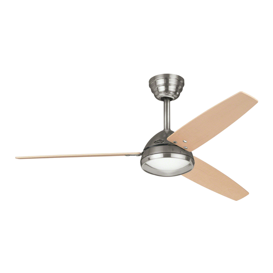
- Page 3 English Congratulations! Your new Hunter ceiling fan is an addition to your home or Espanol office that will provide comfort and reliable performance for many years. We are proud to supply you with the best ceiling fan available anywhere in the world. Before installing your fan,...
- Page 4 à la garantie. Voir la plaque signalétique Hunter sur le haut de votre ventilateur pour les renseignements pertinents. Assurez- vous de conserver votre reçu pour vos dossiers.
- Page 5 Nederlands Grattis! Gefeliciteerd! Din nya Hunter-fläkt är ett tillbehör för ditt hem eller kontor Uw nieuwe Hunter plafondventilator is een verrijking van om kommer att erbjuda både komfort och pålitlig drift under uw woning of kantoor die u de zekerheid geeft van jarenlang många år framöver.
- Page 6 Hunter offers several accessories to complement your fan Deutsch such as wall-mounted or remote speed controls and exten- sion down-rods for ceilings higher than 2,6 m. To ensure wobble-free and stable performance, all Hunter fans use 2 cm inner-diameter pipe for extensions. Follow the instructions for use and installation included with the Hunter accessory. For quiet and optimum performance of your Hunter fan, use only Hunter speed controls and accessories.
- Page 7 équilibrée et stable, le diamètre intérieur des tiges d’extension de tous les ventilateurs Hunter est de 2 cm. Suivre les directives jointes à l’accessoire Hunter pour son Francais installation et son utilisation. Pour une performance silencieuse et optimale de votre venti- Italiano lateur Hunter, n’utiliser que des commandes de vitesse et des accessoires Hunter.
- Page 8 Tillvalstillbehör onderdelen zorgvuldig. Als één van de propellerbladen besch- Hunter erbjuder många olika tillbehör som tillval till din fläkt adigd is, stuur dan alle propellerbladen voor vervanging terug. såsom väggmonterade eller fjärrstyrda kontrollenheter för Als u meer dan één plafondventilator installeert, houd dan hastighet och förlängningsstänger för tak högre än 2,6 meter.
- Page 9 English How to Use This Manual Be sure to read the entire manual before beginning installa- Espanol tion and save any extra parts for future use. This manual will help you install, operate, and maintain your new fan. These instructions are designed to make installation and assembly as Deutsch simple and efficient as possible. Each step has four compo- nents: 1.
- Page 10 Francais Comment Utiliser ce Manuel Assurez-vous de lire la totalité du manuel avant de commenc- Italiano er l’installation et garder toutes les pièces en sus pour une fu- ture utilisation. Si vous n’êtes pas familier avec le câblage, vous devriez engager un électricien qualifié. Ce manuel vous aidera Dansk à...
- Page 11 Suomi Näiden Ohjeiden Käyttö Lue kaikki ohjeet ennen kuin aloitat asennuksen, ja talleta Svenska ylimääräiset osat myöhempää tarvetta varten. Sähkötyöt on annettava ammattitaitoisen sähköasentajan tehtäväksi. Näistä ohjeista on apua uuden tuulettimen asennuksessa, käytössä Nederlands ja huollossa. Nämä ohjeet on tarkoitettu tekemään asennus ja kokoaminen mahdollisimman helpoksi ja tehokkaaksi.
- Page 12 WARNING! • To avoid possible electrical shock, before installing your fan, disconnect the power by turning off the circuit break- ers to the outlet box and associated wall switch location. If you can not lock the circuit breakers in the off position, securely fasten a prominent warning d evice, such as a tag, to the service panel.
- Page 13 MISE EN GARDE! • Pour éviter un choc électrique possible, avant d’installer votre ventilateur, déconnecter l’alimentation électrique en mettant hors tension les disjoncteurs de la prise et de l’interrupteur mural correspondant. Si vous ne pouvez pas verrouiller les disjoncteurs en position fermée, attacher un dispositif de mise en garde visible, comme une étiquette, au panneau électrique principal.
- Page 14 VAROITUKSIA! • Mahdollisen sähköiskun välttämiseksi virta on kytkettävä pois tuulettimelle käytettävistä sähkörasioista ja seinäkyt- kimistä ennen asennuksen aloittamista. Jos suojakat- kaisimia ei voi lukita pois päältä, kiinnitä sähkötauluun selvästi erottuva varoituslipuke. • Kaikki sähkötyöt on tehtävä kansallisten ja paikallisten sähkömääräysten mukaisesti. Sähkötyöt on annettava am- mattitaitoisen sähköasentajan tehtäväksi.
- Page 15 2,6 m >2,3 m This fan may only be mounted using a standard mounting style as outlined in this manual. Standard Mounting is the most common way to mount a ceiling fan. Standard mounting is recommended for ceilings 2,6 m or higher. If you have a concrete ceiling, follow steps 1-5 before proceeding to step 11. If you have a non- concrete ceiling, follow steps 6-10 before proceeding to step 11. Este ventilador sólo puede montarse con un tipo de montaje estándar, como se describe en este manual. El montaje estándar es la forma más común de montar un ventilador de techo. Se incluye una varilla que permite suspender el ventilador algo más bajo. Se recomienda el montaje estándar para techos de 2,6 m (8,5 pies) o más altos. Si tiene un techo de concreto, siga los pasos 1 hasta 5 antes de avanzar al paso 11. Si tiene un techo que no es de concreto, siga los pasos 6 hasta 10 antes de avanzar al paso 11.
- Page 16 65 mm 50,8 mm 3,5 mm 3,5 mm For a concrete ceiling: Drive the M5 x 30 mm expansion anchors [a] into the holes until the ends are flush with the ceiling. Leave the supply mains at least 150 mm Identify the supply mains in the ceiling and drill two holes using the ceil- long for connection to the fan.
- Page 17 Place the three black rubber isolators [a] into the round ceiling plate Thread the supply mains [a] through the center hole of the ceiling holes [b]. plate [b]. Coloque los tres aisladores de caucho [a] negros en los agujeros re- Pase los alambres de la alimentación de la red [a] a través del agujero dondos de la placa de techo [b].
- Page 18 65 mm 50,8 mm 3,5 mm Align two opposing oval slots in the ceiling plate [a] with the M5 x 30 For non-concrete ceilings: mm expansion anchors [b]. Screw the matching M5 x 30 mm screws Drill two pilot holes into the wood support structure using the ceiling [c] into the anchors [b] until the isolators [d] are tight against the ceil- plate [a] as a guide for measurement and accuracy.
- Page 19 Place the three black rubber isolators [a] into the round ceiling plate Place a flat washer [a] on both of the wood screws [b]. holes [b]. Coloque los tres aisladores de caucho [a] negros en los agujeros re- Coloque una arandela plana [a] en ambos tornillos para madera [b]. dondos de la placa de techo [b].
- Page 20 Thread the supply mains [a] through the center hole of the ceiling Raise the ceiling plate [a] and align two opposing oval slots with the plate [b]. pilot holes [b]. Insert and tighten the two wood screws [c] with wash- ers [d] to secure the ceiling plate [a] to the ceiling.
- Page 21 Warning! To reduce the risk of fire, electrical shock, or motor damage, do not lift or carry the fan by the lead wires. To prevent damage to the wires on the bottom of the fan assem- bly, do not sit fan on hard surface. Use foam inside box as support. ¡Advertencia! Para reducir el riesgo de incendio, choque eléctrico, o daño al motor, no levante ni transporte el ventilador llevándolo por los alambres.
- Page 22 Remove the hex bolt [a] from the bracket adapter [b] by removing the Pull the motor lead wires [a] through the pipe [b]. pin [c], hex nut [d] and washers [e]. Retire el perno hexagonal [a] del soporte del adaptador [b] en el ven- Tire los extremos de los alambre del motor [a] a través del tubo [b].
- Page 23 Align the holes in the pipe [a] with the holes in the bracket adapter Push the straight side of the pin [a] through the hole in the hex bolt [b]. [b], and install the hex bolt [c] and washer [d]. Secure with two wash- ers [e] and hex nut [f] on the other side of the pipe.
- Page 24 Laisser temporairement le pavillon supérieur reposer sur le pavillon inférieur [c]. Fare scorrere la calotta inferiore [a] (con il logo Hunter) sull’asta [b]. Far scivolare la calotta superiore [a] sul tubo [b] che guarda in direzi- one opposta facendo sì che l’estremità aperta del cono sia rivolta in alto verso il soffitto.
- Page 25 Pull the motor lead wires [a] through the hanger bracket [b] and Slide the black wedge [a] onto the wires and place it around the top of Trilobular™ ball [c]. the pipe [b]. Tire los extremos de los alambres [a] del motor a través del soporte de Deslice la cuña negra [a] sobre los alambres y colóquela alrededor de la suspensión [b] y bola Trilobular™...
- Page 26 Align the openings in the wedge [a] with the holes in the pipe [b]. Pull the Trilobular™ ball [a] up over the wedge [b] and allow the ends Insert the pin [c] through the holes to stabilize the wedge [a]. of the pin [c] to sit in the cutout area of the ball.
- Page 27 Insert the positioning screw [a] into the Trilobular™ ball [b] and Lift the fan and position the three tabs on the hanger bracket [a] with securely tighten. The top of the positioning screw [a] will rest on the the three matching slots on the ceiling plate [b] then rotate counter- wedge [c] and hold the ball in place.
- Page 28 Loosely install the three assembly screws [a] until all holes in the hanger bracket [b] and ceiling plate [c] are properly aligned, then securely tighten each screw. Instale con holgura los tres tornillos de montaje [a] hasta que los agujeros en el soporte de suspensión [b] y la placa de techo [c] estén alineados correctamente y luego apriete firmemente cada tornillo.
- Page 29 Warning! To avoid possible electric shock, before wiring the fan, disconnect power by turning off the circuit breakers to both the outlet box and its associated wall switch location. If you cannot lock the circuit breakers in the off position, securely fasten a prominent warning device, such as a tag, to the service panel. All wiring must be in accordance with national and local electrical codes.
- Page 30 Pull the supply mains [a] through the side of the hanger bracket [b]. This is the procedure for steps 26-29. Thread the end of each wire into the terminal block [a] on the hanger bracket [b], then secure each supply main [c] by tightening the small setscrews [d]. Pase el alambre de alimentación de la red [a] por el lado del soporte Este es el procedimiento para los pasos 26 al 29. Pase el extremo de cada de suspensión [b].
- Page 31 Neutral wire [a] (blue) to terminal [b] marked "N". Earth wire [a] (green/yellow) to terminal [b] marked Alambre neutro [a] (azul) a terminal [b] marcado "N". Alambre de tierra [a] (verde/amarillo) al terminal [b] marcado Erdungskabel [a] (grün/gelb) zum mit bezeichneten Anschluss [b] Neutrales Kabel [a] (blau) zum mit "N“ bezeichneten Anschluss [b]. Fil neutre [a] (bleu) à la borne [b] identifiée "N". Fil de terre [a] (vert/jaune) à la borne [b] identifiée Filo neutro [a] (blu) al terminale [b] contrassegnato “N”.
- Page 32 Line wire [a] (brown) to terminal [b] marked "L". An additional “L” terminal is provided for separate control of the light kit if a separate line is provided for that purpose. Alambre de línea [a] (marrón) a terminal [b] marcado "L". Se proporciona una “L” adicional para el control separado del con- junto de luz para el caso en que haya una línea independiente para ese propósito.
- Page 33 Attach the plug connector [a] from the terminal on the hanger Excess wire may be placed into the outlet box [a] for non-concrete ceil- bracket [b] to the plug connector [c] on the fan wires [d]. ings, or inside the hanger bracket [b] for concrete ceilings. Conecte el conector [a] del terminal en el soporte de suspensión [b] El exceso de alambre puede ser colocado en la caja de salida [a] para con el conector [c] en los alambres del ventilador [d].
- Page 34 Warning! Raise the canopy [a] over the hanger bracket [b] and align the three Be sure no bare wire or wire strands are visible after making connections. holes of the canopy [a] with the ceiling plate [c]. Failure to complete the following steps carefully could result in the fan fall- ing.
- Page 35 Loosely install the three assembly screws [a] until all holes are To allow room for installing the fan blades, raise the lower canopy above properly aligned, then securely tighten each screw. the fan motor and secure the two setscrews [a]. Instale con holgura los tres tornillos de montaje [a] hasta que los Para permitir espacio para instalar las paletas del ventilador, levante la agujeros estén correctamente alineados y luego apriete firmemente...
- Page 36 Attach each blade [a] to the blade iron [b] using three barrel nuts [c] Attach each blade iron [a] to the fan motor [b] with two and three decorative screws [d] as shown. You may place the decora- blade iron mounting screws [c] and rubber isolators [d]. tive screws and barrel nuts facing up or down.
- Page 37 Lower the lower canopy [a] over the top of the fan motor [b], allowing To install the wall control, you must first remove the faceplate and the rectangular hole to fit over the reversing switch [c], and securely switch assembly from the existing wall control, if you have one. Save the tighten the two set screws [d] against the pipe. The canopy will rest on screws from the faceplate to use for the new one.
- Page 38 Note: Shown assembled to face plate. Face plate is not provided. Connect the wire from the fan [a] and the wire from the wall [b] to Connect the wires from the capacitor [a] to the terminal [b] as the terminal [c] as follows: follows: Line out from the fan to terminal 1. Tighten the set screw. Grey from the capacitor to terminal 1. Tighten the set screw. Supply in from the wall to terminal 2 . Tighten the set screw. Brown from the capacitor to terminal 3 .
- Page 39 Be sure no bare wire is exposed at the connection points. Push the Turn on the electrical power to the fan. wires into the electrical box and mount the wall control assembly [a] to the wall electrical box using the two screws [b] previously removed. Asegúrese de que no queden expuestos conductores desnudos en los Encienda la alimentación eléctrica al ventilador. puntos de conexión. Introduzca los cables en la caja de empalmes y monte el conjunto del control de pared [a] a la caja de empalmes de la pared con los dos tornillos [b] que se retiraron previamente. Stellen Sie sicher, dass kein blanker Draht an den Verbindungspunkten Schalten Sie die Stromversorgung für den Ventilator ein. bloßliegt. Drücken Sie die Kabel in den Stromkasten und montieren Sie die Wand-Kontrolleinheit an den Wand-Stromkasten [a], wobei die beiden vorher entfernten Schrauben [b] zu benutzen sind.
- Page 40 Fan low Fan medium Fan high Fan off Ventilador más baja Ventilador mediano Ventilador más alta Apagar el ventilador Ventilator niedrig Ventilator mitttel Ventilator hoch Ventilator aus Ventilateur faible Ventilateur moyenne Ventilateur forte Ventilateur éteinte Ventilatore bassa Ventilatore media Ventilatore alta Ventilatore spenta Middel Høj...
- Page 41 English Reversing Your Fan To change the direction of the Espanol airflow, turn the fan off and wait for it to come to a complete stop. Deutsch Slide the reversing switch on the fan to the opposite position then restart the fan. English Espanol Deutsch...
- Page 42 Francais Comment inverser votre ventilateur Pour changer la direction de la cir- Italiano culation d’air, arrêter le ventilateur et attendre qu’il s’arrête complète- Dansk ment. Placer le commutateur de marche arrière du ventilateur sur la position opposée et repartir le ventilateur.
- Page 43 Suomi Tuulettimen suunnan vaihtaminen Vaihda ilmavirran suuntaa kytke- Svenska mällä tuuletin pois päältä ja odota kunnes se pysähtyy kokonaan. Nederlands Siirrä suunnanvaihtokytkin vastak- kaiseen asentoon ja käynnistä tuuletin uudelleen. Suomi Svenska Nederlands Lämpimällä säällä kattotuulettimet toimivat parhaiten, kun ne puhal- tavat ilmaa alaspäin (vastapäivään) viilentäen sitä.
-
Page 44: Limpieza Y Mantenimiento
Painted and high-gloss blades may be cleaned in the same manner as the fan finish. Espanol If you need parts or service assistance contact your Hunter Fan retailer or visit out website at Deutsch http://www.hunterfanglobal.com. - Page 45 Il faut nettoyer les pales peintes et ultra brillantes de la même manière que le fini du ventilateur. Dansk Si vous avez besoin de pièces ou d’aide, communiquez avec votre revendeur Hunter Fan ou rendez-nous visite sur notre site Web au http://www.hunterfanglobal.com. Francais...
- Page 46 Gelakte en hoogglanzende propellerbladen reinigt Hunter-återförsäljare eller besök vår hemsida på u op dezelfde manier als de afwerklaag. http://www.hunterfanglobal.com. Als u losse onderdelen of service-assistentie nodig hebt, neem dan contact op met uw Hunter Fan leverancier of surf naar onze website op http://www.hunterfanglobal.com.
-
Page 47: Troubleshooting
English Troubleshooting Problem: Nothing happens; fan does not move. Espanol Solution: Deutsch • Turn power on, replace fuse, or reset breaker. • Loosen canopy, check all wiring connections. • Push reversing switch firmly up or down. Problem: Noisy operation. Solution: • Tighten blade assembly and blade mounting screws until snug. • Replace all blades. English Problem: Excessive wobbling. Espanol Solution: • Use balancing kit included with fan. Deutsch • Tighten all screws. • Turn power off, support fan very carefully and check that the Trilobular™... -
Page 48: Dépannage
Francais Dépannage Problème : Rien ne se passe; le ventilateur ne tourne pas. Italiano Solution : Dansk • Remettre sous tension, remplacer le fusible ou réarmer le disjoncteur. • Ouvrir le pavillon et vérifier toutes les connexions du câblage. • Pousser le commutateur d’inversion fermement vers le haut ou le bas. Problème : Fonctionnement bruyant. Solution : Francais • Visser les vis d’assemblage et de fixation de pales jusqu’à serrage complet. Italiano • Remplacer toutes les pales. - Page 49 Suomi Vianetsintä Ongelma: Mitään ei tapahdu, tuuletin ei liiku. Svenska Ratkaisu: Nederlands • Kytke virta päälle, vaihda sulake tai kytke turvakatkaisin päälle. • Avaa kupua ja tarkista kaikki sähköliitännät. • Paina suunnanvaihtokytkintä tiukasti ylös tai alas. Ongelma: Äänekäs toiminta. Ratkaisu: • Kiristä siivet ja siipien asennusruuvit hyvin. • Vaihda kaikki siivet. Suomi Ongelma: Liika huojunta. Svenska Ratkaisu: • Käytä tuulettimen mukana toimitettua tasapainotuspak- Nederlands kausta. • Kiristä kaikki ruuvit. • Kytke virta pois, tue tuuletin hyvin ja tarkista, että Trilobu- lar™-ripustuspallo on oikein paikallaan.
- Page 50 44214 03/28/2008...
Need help?
Do you have a question about the Metro FAN24211METBN and is the answer not in the manual?
Questions and answers