
Related Manuals for Etesia ET MOWER ETM105


Summary of Contents for Etesia ET MOWER ETM105
- Page 1 Original user Please read carefully before using your machine manual ET MOWER ETM105...
-
Page 2: Table Of Contents
Setting up the peripheral wire: Islands ............................10 Setting up the charging station ..............................11 Safety alert: Error message ................................. 12 Important points to verify ................................13 OPERATING AND MAINTENANCE MANUAL FOR THE ETM105 ROBOTIC ETESIA Description ....................................15 Pictures ....................................... 16 Technical characteristics ................................20 Operating instructions ................................. -
Page 3: Your Safety And That Of Others
HANK YOU ! You are now the proud owner of an Etesia automatic robot mower! • In accordance with article L.111-3 of the consumer code, This extremely reliable and tough machine has been specially designed ETESIA undertakes to supply your dealership with spare parts, to give many years of service. -
Page 4: Set-Up Instructions For The Etm105 Etesia
SET-UP INSTRUCTIONS FOR THE ETM105 ETESIA The installation of the boundary wire and the charging station are essential to ensuring your robot can work effectively. Furthermore, the electrical installation (connecting the charging station to the electricity supply) must be carried out by a professional. - Page 5 1• KEY TO DIAGRAMS...
-
Page 6: Usual Distances
2• USUAL DISTANCES These distances are used in several cases. Every terrain is different and it must be kept in mind that different constraints are found in each case. During set up, the installer must work as follows: ETM105 Reminder: - length of mowing: 105 cm;... - Page 7 2• USUAL DISTANCES 2•3 NARROW PATHWAYS If the area being mown has narrow passageways or areas certain minimum dimensions must be complied with to ensure the mower operates correctly and to ensure it can get back to the base unit. Minimum distance between wires (l) Length of narrow <...
- Page 8 2• USUAL DISTANCES If the length of the perimeter wire exceeds the length of a spool of ETESIA ETC or ETC1 wire (500 m), a connection will have to be made using an ETK connector according to the procedure described below.
- Page 9 If the perimeter wire is modified or repaired after the robot is installed, due to the wire being cut, adding a plot, increasing the size of the mowing area and so forth, it is imperative to use Etesia ETK connectors to connect the cables to ensure the join is...
-
Page 10: Setting Up The Peripheral Wire: Islands
If the water point is on a downward slope, you Island: more than 5 m must provide physical obstacles. away from a pseudo-island ETESIA decline all responsibility if the robot falls into the water. 3•3 DISTANCES REGARDING THE Island: more than PERIPHERAL WIRE... -
Page 11: Setting Up The Charging Station
4• SETTING UP THE CHARGING STATION For optimal operation, the charging station must be placed in 4•3 ADJUSTING THE CHARGING ARM the main area of the terrain, offering the greatest clearance possible. Set the height and angle of the charging arm depending on the position of the robot, the base unit and the slope of the ground to For best results install the base unit on a paved or concrete area. -
Page 12: Safety Alert: Error Message
5• SAFETY ALERT: ERROR MESSAGE Etesia robots indicate their status with beeps or with messages on the display. The ETB charge unit also indicates its status with a two coloured LED. ROBOT STATION Beeps - 1 long beep: stop machine, or mistake on the keypad... -
Page 13: Important Points To Verify
6• IMPORTANT POINTS TO VERIFY 6•1 DURING SET-UP 14. The station must be positioned on a flat surface of min. 2 metres in front of the station arm. In addition it must have the straightest line possible for 3 metres on both sides of the 1. -
Page 15: Operating And Maintenance Manual For The Etm105 Robotic Etesia
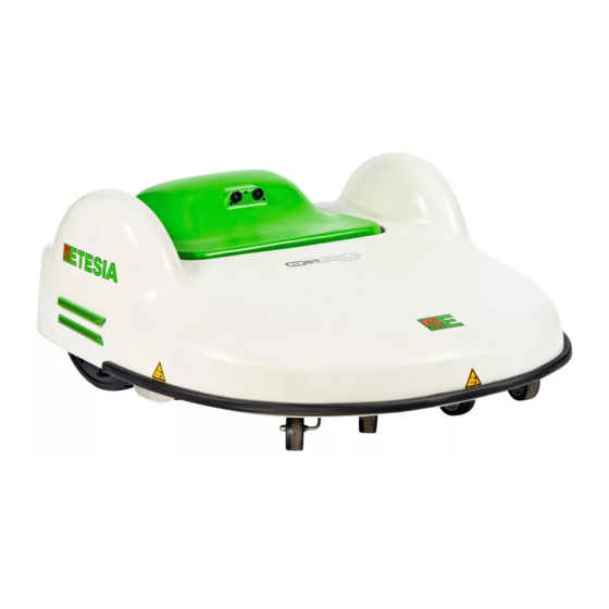
OPERATING AND MAINTENANCE MANUAL FOR THE ETM105 ETESIA 1• DESCRIPTION The robot mower ETM105 is a completely automatic lawnmower. It Its electronics and computer system manage all the information supplied by its many sensors in real time. is used to maintain areas of up to 2 hectares. Enabling its owner to... -
Page 16: Pictures
2• PICTURES... - Page 17 2• PICTURES...
- Page 18 2• PICTURES (ETBA) 67 cm 67 cm...
- Page 19 2• PICTURES (ETBA) Zone A Zone C Recovery zone Zone B Zone C Zone A 2100m² Zone A Zone B Channel selector Zone B 7200m² 5200m² Zone C Zone A Min. Angle distance < 5 m Close to the station : Away from the station : wires overlapping one (and min.
-
Page 20: Technical Characteristics
3• TECHNICAL CHARACTERISTICS DESIGNATION CHARACTERISTICS Thrust 125 W / 2 wheels, Ф45cm Cutting height From 22 to 80 mm in 11 positions Cutting width 105 cm / 5 heads Cutting disc motor 24 Volts brushless Working speed 3.6 km/h Maximum rotation speed 3500 rotations/min Motor wheel engine 24 Volts brushless... - Page 21 4• OPERATING INSTRUCTIONS 4•5 CONFIGURATION OF THE ROBOT 4•3•2 MODIFICATION OF THE CUTTING HEIGHT MOWER ETM105: KEYPAD 4•5•1 USE OF THE KEYPAD PROCESS MEANINGS The keypad includes 17 keys (10 numbers and 7 action keys) : Open the cover (picture 7a) Lift the selection needle (picture 7b) Slide the selection bar to the desired height (picture 7c)
- Page 22 4• OPERATING INSTRUCTIONS STRUCTURE OF THE MENUS (ACCORDING TO PROCESS MEANINGS SOFTWARE) The screen will now be showing " # - - - - ". Enter Menu your new code, confirm by pressing #, enter the number of days and confirm by pressing #. Settings Options To delete the PIN code, enter ‘0000’...
- Page 23 4• OPERATING INSTRUCTIONS Example 1 : The robot rests from 9pm on Monday and starts CODES MEANINGS working again the following day at 6am. →Go Start to work Rest range 1# : 21 : 00 → 24 : 00 Switched on Mon □Tue □Wed □Thu □Fri □Sat □Sun ...
- Page 24 4• OPERATING INSTRUCTIONS 4•9•1 OPTION «O00 - MULTIROBOT» ROBOT CHARGING STATION Beeps The "MultiRobot" option must be selected if several robots are working in the same area. - 1 long beep: Stop robot or incorrect key has been pressed From the "OPTIONS" screen, press # - F2 and use the # again to - 1 short beep: Key has been pressed - Blinking green light: OK, normal select or deselect the option.
- Page 25 4• OPERATING INSTRUCTIONS 4•9•6 OPTION "O08 - PHIINV" 4•9•11 OPTION "O14 - BACK ALONG WIRE" This option should only be used by your authorised dealer. This option defines the station return path. This option is used only the first time you switch on your robot, to With Back Along Wire enabled, the robot follows its wire back to choose the correct phase in accordance with the installation of the the station.
-
Page 26: Settings
5• SETTING 5•1 SETTING UP THE PERIPHERAL 5•3•2 MAXIMUM DEGREE OF SLOPE OF THE TERRAIN (PICTURES 16 AND 17) WIRE: TERRAIN BOUNDARIES (PICTURE 15) The slope limit is 30% (approximately 15°). Beyond this limit, the robot mower ETM105 risks slipping in difficult conditions (humidity, rain, uneven density of the terrain etc.). - Page 27 Place the loading station in the base and be sure that you can always insert the loading station after filling from the side (picture 27). IT IS ESSENTIAL TO USE THE CABLE ETESIA ETC OR ETC1. - Twist the peripheral wire and bury it in direction to the base in order to protect it.
-
Page 28: Multizone Option
1, 2 of the figure 1), the robot never changes zone but still sometimes (Please contact your Etesia dealer if you cannot find the software for passes through the recovery zone included in the selected work zone. - Page 29 6• MULTIZONE OPTION 6•2•2 DESCRIPTION OF THE PARAMETERS / The possible values for option 15 are: OPTIONS Option 15 (Zone X) = 0: The rest times programmed for zone Z are active, i.e. the robot takes them into consideration They allow the user to control the algorithm used by the robot to and cannot work in zone X during these periods.
- Page 30 6• MULTIZONE OPTION 6•2•6 P10 PARAMETERS: WORKING TIME RATIO However, this rule is only correct if the user does not bias the robot’s behaviour by assigning different rest times for the zones. The P10 parameter is a multi-zone parameter, i.e. each zone (A, B and C) has its own P10 value.
- Page 31 6• MULTIZONE OPTION P008 (Zone A) = you have to program the same setting (0, 1, 2, Once the correct zone is displayed, press F1 on the keyboard in 3, 4 or 5) as the channel selector in the station board which is order to activate a return to the station.
- Page 32 6• MULTIZONE OPTION 6•5•1 OPTION O008: PHASE INVERSION 6•5•2 OPTION O016: MULTIZONE This option activates or deactivates multizone mode. Inside the peripheral wire loop, i.e. in the zone where the robot is If it is deactivated (-) (default setting), the robot can only work in a to work, the robot always has to “see”...
- Page 33 6• MULTIZONE OPTION FIG 2 : The topmenu contains four possible different screens (see figure 2) and you press the button to move from one screen to another. The four possible screens are: *13870 "Global menu" identified by the presence of the time. Menu tu 19/02 27,2...
-
Page 34: Maintenance
Return anticlockwise: Option 0010 = (−) and in one direc- recovery zone, especially in line (above) one of the wires tion: Option 011=(−) forming a magnetic loop, please contact ETESIA. Installing an additional supply in the station may resolve the problem. Sonar for station pointing south •... - Page 35 7• MAINTENANCE 7•6 SPARE PARTS OF THE ROBOT It is recommended that you give it a service during the winter so that your dealer can analyse the history of your robot mower MOWER ETM105 ETM105 via a connection to a laptop. If the maintenance contract stipulates it, please get in touch with your dealer in order to arrange 7•6•1 THE CUTTING BLADES KIT an annual maintenance check.
-
Page 36: Troubleshooting
8• TROUBLESHOOTING PROBLEMS SITUATION SOLUTION Check whether the body moves freely and check that Body position connector in permanent contact. the contacts are properly in the body inserts. Operates in reverse The phase of the peripheral wire is reversed. The robot Reverse the phase: see 4•9•6 or reverse the wires spins round and shows stuck on wire. - Page 37 8• TROUBLESHOOTING PROBLEMS SITUATION SOLUTION Plug it in. The LED at the back of the station is not switched on. The station is unplugged. Wait for the network power to go back on. The LED at the back of the station is flashing red. Call the dealer to come and repair it.
- Page 38 8• TROUBLESHOOTING PROBLEMS SITUATION SOLUTION Check that there are no muddy areas in the machine’s path. The machine travels an abnormal distance in comparison with the terrain without finding its Machine Alarm Indication: The number of metres of peripheral wire encoded in peripheral wire.
-
Page 40: Installation And Operating Instructions For The Gps / Gprs Module
• a GSM/GPRS unit, allowing communications, through SMS/data sent over the GSM/GPRS network, to: The GPS/GPRS module is an optional functionality of your ETESIA - the ETESIA ‘Track&Trace’ server storing information about the lawnmower. It is a performance tool offering the following features: robot (status, position, alarms,…). - Page 41 3• USING TEXT MESSAGES TO CONTROL THE GPS/GPRS MODULE 3•2 CONFIGURING GPS/GPRS MODULE If this command is used when neither the ‘ALARM_PHONE’ nor ‘CONTROL_PHONE’ numbers are defined, they are both set with PHONE NUMBERS the number of the phone which sent this command. The first operation to perform before using ‘Track&Trace’...
- Page 42 3• USING TEXT MESSAGES TO CONTROL THE GPS/GPRS MODULE ‘Status’ command sent from ‘ALARM_PHONE’ Robot answering confirmation that CONTROL_PHONE has been set. In the mean time, the robot has also switched off (Robot=0). ‘Clearctrlphone’ command sent from ‘ALARM_PHONE’. Robot answering confirmation that CONTROL_PHONE has been cleared.
- Page 43 3• USING TEXT MESSAGES TO CONTROL THE GPS/GPRS MODULE The ‘Position’ command is sending back: - ID = unique identification number of the GPS/GPRS module embedded in the robot - Position : Last valid position acquired by the GPS receiver as well as the corresponding time Position. - A Google map link on which you can click to see the corresponding position.
- Page 44 3• USING TEXT MESSAGES TO CONTROL THE GPS/GPRS MODULE The command ‘TimerOff’ is temporarily disabling the timers defining the periods during which the robot may not operate. So,‘TimerOff’ will force the robot to work continuously unless the command ‘BackHome’ has been given which has priority over ‘TimerOff’.
- Page 45 3• USING TEXT MESSAGES TO CONTROL THE GPS/GPRS MODULE 3•5•2 TIMEROFF X AND TIMERON X COMMANDS Below snapshots show SMS messages of TimerOff X command The commands TimerOff X and TimerOn X have the same functionality applied to Zone as the global commands TimerOff and TimerOn described in chapter 3•4 but for the sole specified zone X (X = A, B or C).
-
Page 46: Using 'Track&Trace' Server On The Web
3• USING TEXT MESSAGES TO CONTROL THE GPS/GPRS MODULE 3•7 ALARM_SMS The GPS/GPRS module is sending Alarm_SMS to the ‘ALARM_ - Security threat detection: robot leaving the zone defined by the PHONE’ and the ‘ALARM_PHONE2’ only. The events causing an virtual fence (see section 3•6) or GPS/GPRS module detecting Alarm_SMS are: abnormal move (speed >10km/hr or distance between initial... - Page 47 4• USING ‘TRACK&TRACE’ SERVER ON THE WEB 4•2 PAGE ‘MANAGE’ Phone N° of the robot : To always have the phone number at hand Search Bar : To rapidly search a robot in a long list. to communicate with the robot. Free Text Zone : To add a text to facilitate the recognition of the DATA, history of the robot : To download the data to be inserted in robot (Field A, Foot2,…).
- Page 48 4• USING ‘TRACK&TRACE’ SERVER ON THE WEB In DTS 6.0 : Clic « import binary » and select the downloaded file. - For the sub-menu ‘General’, ‘Events’ and ‘Geozone’, check the box 4•3 PAGE ‘MAP’ as listed below. 1 'FILTER' ICON - Do not use the sub-menu ‘Filter’.
- Page 49 4• USING ‘TRACK&TRACE’ SERVER ON THE WEB 2 ‘OBJECTS’ ICON - Search the related robot using the search tool. • • - Check the box. To select the robot you want to see based on the selected filters (see - Click on the Update icon. picture below).
- Page 50 4• USING ‘TRACK&TRACE’ SERVER ON THE WEB 4•4 PAGE ‘REPORTS’ - Select the robot in the ‘Map description’. To get more details (location of the error) analysing the informations - Select the range of date for which you want to see the information. with the reading of the history in DTS.
-
Page 51: Frequent Issues And Questions
5• FREQUENT ISSUES AND QUESTIONS PROBLEMS SOLUTIONS The SMS communication between your mobile phone and the robot is not working. Following possibilities can explain the problem: - you have mistyped the robot SIM card phone number. - the GSM network of the operator is temporally not working in your area or in the area of the robot. - Page 52 Dealer Tool Suite software There are five different ‘clock’ references involved in the system: - The clock of the robot that you can define through the keyboard (refer to ETESIA robot user manual). - The clock that the ‘Track&Trace’ module is capturing directly from the GPS satellites.
-
Page 53: Warranty
; parts with • Should ETESIA discover that the machine is not used in the use normal wear. initially declared, ETESIA allows itself to cancel the warranty. - Page 54 Model: Année de fabrication Serial number: Done in Wissembourg, the 18/07/2016 Due to their permanent improvement policy, ETESIA reserves the Mr. Patrick VIVES right to modify specifications, text and pictures without prior notice. 13, Rue de l’Industrie - F- ETESIA SAS -...
- Page 55 Stamp here please ETESIA SERVICE GARANTIE 13 rue de l'Industrie 67165 WISSEMBOURG CEDEX France...
- Page 56 This card has to be returned completed to ETESIA upon the first setting up. MODELL: SERIAL NUMBER: WARRANTY CERTIFICATE USER NAME ___________________________ Forename _________________________ Street ___________________________ Zip code __________________________ Town __________________________ Country____________________________ Tel ______________________________ Date of purchas _____ _____ 20 ___ Tel.
Need help?
Do you have a question about the ET MOWER ETM105 and is the answer not in the manual?
Questions and answers
Sandbank blck