
Related Manuals for Zoomlion ZA14J


Summary of Contents for Zoomlion ZA14J
- Page 1 ZA14J (ZA45J) Operation and Safety Manual Zoomlion Heavy Industry Science & Technology Co.Ltd. Postcode: Add:No 361South Yinpen Rd Changsha Hunan Province P.R.China 410013 E-mail:...
- Page 3 Operation and Safety Manual ZA14J (ZA45J) Operation and Safety Manual Comply with ANSI SAIA_A92.20-2018 and CSA-B354.6-2017 Standard 2019.5 A...
- Page 5 ZOOMLION appreciates your choice of our machine for your application. The Operation and Safety Manual must be read and understood in its entirety before operating the machine. This manual introduces you safety information, significant technical specs, safety operation in detail for working efficiency improving.
- Page 6 This manual has the following safety precaution icons: Failure to comply with the safety precautions listed in this manual could result in personal injury or death. Failure to comply with the safety precautions listed in this manual could result in potential personal injury or death. Failure to comply with the safety precautions listed in this manual could result in potential mild personal injury.
-
Page 7: Table Of Contents
Contents Foreword ............................. I Safety Precaution Icons ........................II Contents ............................III SECTION 1 SAFETY PRECAUTIONS ..................1-1 1.1 General ............................1-1 1.2 Pre-operation ..........................1-1 1.3 Hazard Classification ........................ 1-2 1.4 Intended Use ..........................1-2 1.5 Safety Alert Symbols and Maintenance ..................1-2 1.6 Safety Operation ........................ -
Page 8: Contents
Contents SECTION 4 OPERATION INSTRUCTION ................4-1 4.1 General ............................4-1 4.2 Machine Operation ........................4-1 4.2.1 Engine operation ..................... 4-1 4.2.2 Drive operation ......................4-3 4.2.3 Platform leveling ..................... 4-4 4.2.4 Platform rotating ..................... 4-5 4.2.5 Turntable slewing ....................4-5 4.2.6 Raise and lowering the upper boom ................ - Page 9 Contents SECTION 6 STORAGE AND EX-FACTORY TEST ..............6-1 6.1 Storage Conditions ........................6-1 6.2 Ex-factory Test Items ........................ 6-1 SECTION 7 TECHNICAL PARAMETER ................. 7-1...
-
Page 13: Section 1 Safety Precautions
1.1 General To Owner/Users/Operations: Zoomlion appreciates your choice of our machine for your application. Safety is the number one priority, which is best achieved by our joint efforts. The following requirements need to be adhere to for the purpose of safety operating. -
Page 14: Hazard Classification
1.3 Hazard Classification Decals on this machine use symbols, color coding, and signal words to identify the following: Safety alert symbol - used to alert you potential personal injury hazards. Obey all safety messages that follow this symbol to avoid possible injury or death. Indicates a hazardous situation which, if not avoided, will result in death or serious injury. - Page 15 Read operational Read service manual Fire hazard No smoking Explosion hazard manual Maintain required Electrocution hazard Burn hazard Prohibit step on Avoid contact clearance Electrocution hazard Tip-over hazard Tip-over hazard Tip-over hazard Tip-over hazard Wheel load Wind speed Maximum capacity Tie-down point Lanyard anchorage points Crushing hazard...
- Page 16 No smoking Runaway hazard Fall hazard Tire disassembly Explosion hazard No flame Stop engine Trained and authorized Platform AC power Prohibit lifting Lifting point Avoid contact personnel operates the machine only Recovery procedure if tilt alarm sounds while elevated Platform downhill: Platform uphill: 1.
-
Page 17: Safety Operation
1.6 Safety Operation 1.6.1 Operator safety Personal Fall Protection Personal fall protection equipment (PFPE) is required when operating this machine. If PFPE is required in job site or in operator’s manual, the following rule should be complied with: All PFPE must comply with applicable governmental regulations, and must be inspected and used in accordance with the PFPE manufacturer’s instructions. - Page 18 Allow for platform movement, electrical line sway or sag, and beware of strong or gusty winds; Keep away from the machine if it contacts energized power lines. Personnel on the ground or in the platform must not touch or operate the machine until energized power lines are shut off. Do not operate the machine during lightning or storms.
- Page 19 machine is on a severe slope. If the tilt alarm sounds when the platform is raised, be extremely careful. Identify the condition of the boom on the slope as shown below. Follow the steps to lower the boom before moving to a firm, level surface.
- Page 20 Be extremely careful and slow speeds while driving the machine in the stowed position across uneven terrain, debris, unstable or slippery and near holes and drop-offs; Do not drive the machine on or near uneven terrain, unstable surfaces or other hazardous conditions with the boom raised or extended;...
- Page 21 Model Manual force Maximum occupants ZA14J 400 N/90 lbs force Do not place or attach fixed or overhanging loads to any part of this machine; Do not place ladders or scaffolds in the platform or against any part of this machine;...
- Page 22 Fall hazards Occupants must wear a safety belt or harness in accordance with governmental regulations. Attach the lanyard to the anchor provided in the platform; Do not sit, stand or climb on the platform guard rails. Maintain a firming footing on the platform floor at all times;...
- Page 23 Collision hazard Be aware of limited sight distance and blind spots when driving and operating; Check the work area for overhead obstructions or other possible hazards; Be aware of crushing hazards when grasping the platform guard rail; Be aware of the boom position and tail swing when rotating the turntable; Operators must comply with employer, job site, and governmental rules regarding use of personal protective equipment.
- Page 24 Do not lower the boom unless the area blow is clear of personnel and obstructions. Limit travel speed according to the condition of the ground surface, congestion, slope, location of personnel, and any other factors which may cause collision. Observe and use the color-coded direction arrows on the platform controls and drive chassis for drive and steer functions.
- Page 25 Immediately tag and remove from service a damaged or malfunctioning machine; Be sure all maintenance had been performed as specified in this manual and the appropriate Zoomlion service manual; Be sure all decals are in place and legible; Be sure operator’s, safety, and responsibilities manuals are complete, legible, and in the storage container located on the machine.
- Page 26 Battery Safety Burn hazard Batteries contain acid. Always wear protective clothing and eye wear when working with batteries; Avoid spilling or contacting battery acid. Neutralize battery acid spills with baking soda and water; Do not expose the battery or charger in water or rain while charging. Explosion hazard Keep sparks, flames, and lighted tobacco away from batteries.
-
Page 29: Section 2 Machine Components And Controls
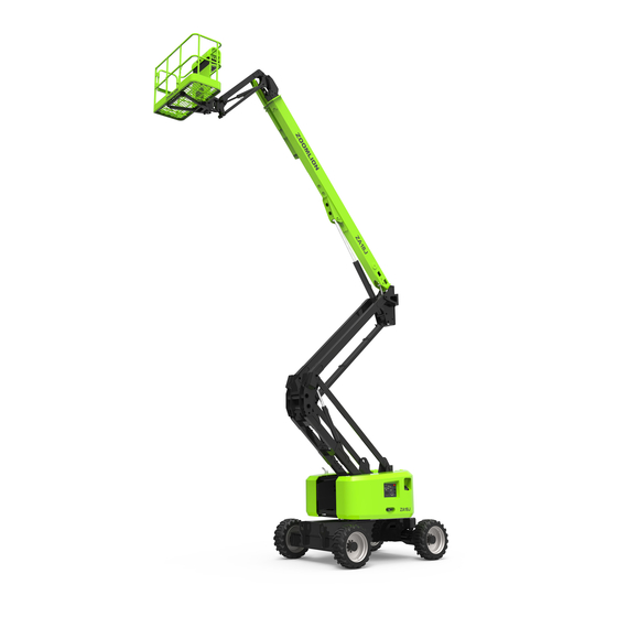
SECTION 2 MACHINE COMPONENTS AND CONTROLS 2.1 Machine Components Figure 2-1 Components Table 2-1 Component instruction Item Item Footswitch Platform Controller Manual Storage Container Main Boom (upper boom) Sliding Mid-rail Tower Boom Lanyard Anchorage Points Ground Control Console Swing Gate Steering Tire Non-steering Tire Work Platform... -
Page 30: Machine Controls And Indicators
2.2 Machine Controls and Indicators The manufacturer had no direct control over machine application and operation. The user and operator are responsible for conforming with good safety practices. 2.2.1 Ground control console 1. Boom lift, boom extend/retract, tower boom lift, turntable swing, jib lift, platform leveling, platform rotating device and auxiliary control device all equip with spring so that they will back to neutral when releasing. - Page 31 Table 2-2 Ground control panel instruction Item Turntable Slew Switch Main Boom Lift Switch Tower Boom Lift Switch Main Boom Telescope Switch Jib Lift Switch Platform Rotate Switch Platform Leveling Switch Power/Emergency Stop Switch Platform/Ground Select Switch Engine Start/Auxiliary Power/Function Enable Switch Display Turntable slew switch Provide 355°non-continuous rotating.
- Page 32 Jib lift switch (if equipped) Provide raising and lowering of the jib. Platform rotate switch Provide platform rotate controls. Only use the platform leveling override function for slight leveling of the platform when platform is lowered. Incorrect use could cause the load/occupants to shift or fall. Failure to do so could result in death or serious injury.
-
Page 33: Ground Control Indicator Panel
To use auxiliary power, operate a single action only. (Compound operation is beyond the capacity of auxiliary pump motor) 10) Engine/Auxiliary power/Function enable switch To start the engine, the switch must be held “UP until the engine starts. Shut off engine and push the switch backward to start auxiliary pump. - Page 34 The function classification is as shown below: Figure 2-4 No.1 indicates title; No.2 indicates fault code; No.3 indicates dynamic parameter monitor; No.4 indicates status indicator, stowed position and work station; No.5 indicates navigation bar. When the articulating boom lift is in stowed position with no fault code and engine failure, the interface is as shown below: Figure 2-5...
- Page 35 When the articulating boom lift is in work position with no fault code and engine failure, the interface is as shown below: Figure 2-6 When the articulating boom lift is in stowed position with engine failure, but no fault code reveals, the interface is as shown below, and the engine failure icon flashes in real time: Figure 2-7 In this case, press the engine fault button to enter the engine fault page.
- Page 36 Figure 2-8 Click ‘Main Interface’ on the navigation bar to return to the interface shown in Figure 2-7. when the system alarm occurs, the fault code and its description are displayed in a scrolling manner as shown below: Figure 2-9 22051 indicates fault code and DTC_GENERATOR_FAULT indicates fault description.
- Page 37 Figure 2-10 When certain states occur, the status indicator lights up and flashes; when the specific state is released, the turntable indicator light return to gray, as shown in the following figure: Figure 2-11...
-
Page 38: Platform Control Console
2.2.3 Platform control console Avoid serious injury, do not operate machine if any control levers or toggle switches controlling platform movement do not return to the off or neutral position when released. Figure 2-12 Platform control panel (only the switch number corresponding to the existing function is identified) Table 2-3 Ground control panel instruction Item... - Page 39 To avoid serious injury, do not operate machine if any control levers or toggle switches controlling platform movement do not return to the off or neutral position when released. Drive select switch Provide high speed, intermediate speed, and low speed. The forward position gives maximum drive speed;...
- Page 40 Before driving, locate the blue/yellow orientation arrows on both the chassis and the platform controls. Move the drive controls in a direction matching the directional arrows. Drive/Steer controller Provide drive/steer controls. Push forward to drive forward, pull back to drive in reverse. Steering is accomplished via a thumb-activated rocker switch on the end of the steer handle.
-
Page 41: Platform Control Indicator Panel
Tower boom lift switch Provide for raising and lowering of tower boom when positioned up or down 2.2.4 Platform control indicator panel Note: the indicator lights will illuminate for approximately 1 second when the key is positioned to the on position to act as a self-test. Figure 2-13 Platform control indicator panel Table 2-4 Platform indicator panel instruction Item... - Page 42 If leveling system fault indicator lights up, shut off the machine and restart. If fault occurs again, retract the platform to stowed position via manual level function, and service the leveling system. Platform overload indicator Indicate the platform has been overload. Wire rope loosen indicator (not equipped) Indicate loosen or damage of main boom wire rope, service or adjust it immediately.
- Page 43 Creep speed indicator When the Function Speed Control is turned to the creep position, the indicator acts as a reminder that all functions are set to slowest speed. The light will be on continuously if the operator selects creep speed. Foot switch indicator To operate any function, the foot switch must be depressed and the function selected with 7 seconds.
- Page 44 12) Low fuel indicator Indicate a low fuel condition in the tank. 13) Limited position indicator Indicate limited position of boom. 14) Limited position indicator Indicate limited position of boom. 2-16...
-
Page 47: Section 3 Machine Inspection
SECTION 3 MACHINE INSPECTION 3.1 General An operator must not operate the machine, only if: He has learned and practiced the principles of safe machine operation contained in this operational manual. Only use the machine as it was intended; Know and understand the pre-operation inspection before going on to the next section; Implement functional test before operating the machine at all times;... - Page 48 Check for battery fluid leaks and proper fluid level. Add oil if needed. See maintenance section; Check for engine coolant leaks and proper level of coolant. Add coolant of needed. See maintenance section; Check the following components or areas for damage, improperly installed, or missing parts and unauthorized modifications: 1) Electrical components, wiring, and electrical cables;...
-
Page 49: Function Check
3.2 Function Check 3.2.1 Function check principle The function tests are designed to discover any malfunctions before the machine is put into service. The operator must follow the step-by-step instructions to test all machine function; A malfunctioning machine must never be used. If malfunctions are discovered, the machine must be tagged and removed from service. -
Page 50: Platform Function Check
button; Attempt to active each boom and platform function button. Test result: all boom and platform functions should operate through a full cycle. Test auxiliary power Shut off the engine at the ground controls; Pull out the red Emergency Stop button to the on position; Operate auxiliary power switch;... - Page 51 Attempt to activate each boom and platform function button. Test result: all boom and platform functions except driving and steering should operate at the auxiliary power mode. Test horn Press the horn at the platform controls. Test result: the horn should sound. Test the steering Start the engine at the platform controls;...
-
Page 52: Workplace Inspection
Lower the upper boom to stowed position; Extend the upper boom 0.5m/1ft 8in; Attempt to operate drive handle; Test result: the drive speed should switch to low speed with the upper boom extended. Lower the upper boom to stowed position; Attempt to operate drive handle. -
Page 53: Decal Inspection
The presence of unauthorized personnel; Other possible unsafe condition. 3.4 Decal Inspection Figure 3-1 Decal position Use the pictures on next page to verify that all decals are legible and in place. Below is a numerical list with quantities and description. - Page 54 Table 3-1 Decal Numbers are corresponded to the decal (not all decal are pasted on the machine) Part. No/Description Decal 00773407000401390 Caution-Preserve the manual 00773407000401400 Label-Read the manual 00773407000201410 Label-Lanyard anchorage point 00773407000201420 Label-Tie down 00773407000201430 Label-Lift 00773407000401440 Caution-Main power operating instruction 00773407000401450 Warn-Pre-inspection...
- Page 55 Table 3-1 Decal (continuous) Numbers are corresponded to the decal (not all decal are pasted on the machine) Part. No/Description Decal 00773407000401460 Label-Platform AC power 00773407000201010 Label-ZOOMLION 00773407000201020 Label-ZOOMLION 00773407000201030 Label-ZOOMLION 00773407000201040 Label-ZA14J 00773707000201010 Label-ZOOMLION (CH) 00773407000201060 Label-Refuel...
- Page 56 Table 3-1 Decal (continuous) Numbers are corresponded to the decal (not all decal are pasted on the machine) Part. No/Description Decal 00773407000401070 Hazard-Electrocution hazards 00773407000401080 Label-Ground controls instruction 00773407000401090 Hazard-Tip-over, Crush hazard 00773407000401100 Label-Wheel load 00773407000401110 Hazard-Tip-over hazard 00773407000401120 Label-Transport and lift instruction 00773407000201130 Label-Slope rating...
- Page 57 Table 3-1 Decal (continuous) Numbers are corresponded to the decal (not all decal are pasted on the machine) Part. No/Description Decal 00773407000401140 Label-Platform console instruction 00773407000401150 Caution-Cut off battery 00773407000401160 Caution-Trained and authorized personnel operates the machine only 00773407000401170 Hazard-Prohibit contact 00773407000201180 Label-Prohibit step on 00773407000401190...
- Page 58 Table 3-1 Decal (continuous) Numbers are corresponded to the decal (not all decal are pasted on the machine) Part. No/Description Decal 00773407000401210 Hazard-Crushing hazard 00773409900401040 ZA14J Plate 00773407000401230 Warn-Foot switch malfunction 00773407000201240 Label-Prohibit lifting 00773407000401250 Label-Plug stop pin when transporting...
- Page 59 Table 3-1 Decal (continuous) Numbers are corresponded to the decal (not all decal are pasted on the machine) Part. No/Description Decal 00773407000201280 Label-Blue arrow 00773407000201290 Label-Yellow triangle 00773407000201300 Label-Blue triangle 00773407000401310 Hazard-Limited switch tip-over hazard 00773407000401320 Warn-Crushing hazard 00773407000401330 Label-Range of motion 00773407000201340 Label-Yellow arrow 3-13...
- Page 60 Table 3-1 Decal (continuous) Numbers are corresponded to the decal (not all decal are pasted on the machine) Part. No/Description Decal 00773407000401350 Hazard-Tip-over hazard, tilt warning 00773407000401360 Hazard-Tip-over hazard, tires 00773407000401370 Hazard-Explosion 00773407000401380 Hazard-Explosion 00773407000401470 Hazard-Burn 00771407000401150 Label-Diesel oil tank 00771407000401160 Label-Hydraulic oil tank 3-14...
- Page 61 Table 3-1 Decal (continuous) Numbers are corresponded to the decal (not all decal are pasted on the machine) Part. No/Description Decal 00771407000401170 Label-Environmental information 3-15...
-
Page 65: Section 4 Operation Instruction
SECTION 4 OPERATION INSTRUCTION 4.1 General An operator must not operate the machine, only if: He has learned and practiced the principles of safe machine operation contained in this operational manual. Avoid hazardous situations; Perform a pre-operation inspection at all times; Implement functional test before operating the machine at all times;... - Page 66 DO NOT OPERATE MACHINE; If an engine malfunction causes a unscheduled shutdown, determine the cause and correct it before restarting the engine; Consult ZOOMLION customer service to know more about the operation under abnormal conditions. 4.2.1.1 Engine start Machine with diesel engines.
-
Page 67: Drive Operation
maintenance manual. 4.2.1.2 Engine shut down Remove all load and allow engine to operate at low speed for 3-5 minutes; this allows further reduction of internal engine temperature; Push Power/Emergency Stop switch; Turn Platform/Ground Select switch to Off. Refer to Engine Manufacturer’s manual for detailed information. -
Page 68: Platform Leveling
4.2.2.1 Traveling forward and reverse At Platform Controls, pull out Emergency Stop switch, start the engine, and activate foot switch; Position Drive/Steer control to ‘Forward’ or ‘Reverse’ hold for duration of forward or reverse travel desire. This machine is equipped with travelling direction indicator lights. The indicator lights on platform console to inform that upper boom is over front axle (Steer Wheels), steer and drive controls will move in opposite direction than indicated on machine placards. -
Page 69: Turntable Slewing
4.2.4 Platform rotation To rotate the platform to the left or right, use the Platform Rotate control switch to select the direction and hold until desired position is reached. Do not swing or raise upper boom above horizontal when machine is out of level. Do not depend on tilt alarm as a level indicator for the chassis. -
Page 70: Raising And Lowering The Tower Boom
4.2.8 Raising and lowering the tower boom To raise or lower the tower boom, position the Tower Boom Lift to Up or Down until the desired height is reached. 4.2.9 Raising and lowering the jib To raise or lower the jib, position the Jib Lift to Up or Down until the desired height is reached. 4.2.10 Emergency stop Push in the red Emergency Stop button on Ground or Platform Controls to off position to shut off all the functions. -
Page 71: Shut Down And Park
Operate appropriate control switch, lever or controller for desired function and hold; Release Auxiliary Power switch, and appropriate control switch or controller; Position Power/Emergency Stop switch to Off. 4.2.12 Shut down and park Drive machine to a protected area; Assure upper boom is fully retracted and lowered over rear (Drive) axle; Remove all load and allow engine to operate 3-5 minutes at idle to permit reduction of engine internal temperatures;... -
Page 72: Transport And Lifting
The transport vehicle must be secured to prevent rolling while the machine is being loaded. Be sure the vehicle capacity, loading surfaces and chains or straps are sufficient to withstand the machine weight. ZOOMLION lifts are very heavy relative to their size. See the serial label for the machine weight. -
Page 73: Lifting
Insert the hook piece through the slots in the panel cradle base. Inspect the entire machine for loose or unsecured items. 4.3.2 Lifting See serial label and Technical Parameters section in this manual for specific machine weight and total weight of the machine; Place the boom in the stowed position;... - Page 74 Figure 4-6 Securing the platform Use a cable tire or rope to secure the slider to the upper square tube of the work platform to prevent the slider form bumping during transportation. Figure 4-7 Securing the platform 4-10...
-
Page 77: Section 5 Maintenance
Disposal of materials should be according to the regulations of government and relevant environmental protection administration; Use only ZOOMLION approved replacement parts. ZOOMLION assumes no responsibility for hazards occurred to equipment and personnel caused by the use of unauthorized parts. -
Page 78: Maintenance Hazards
Wear pads; Tires and wheels; Limit switches and horn; Alarm and indicator (if equipped); Nuts, bolts and other fasteners; Brake release unit. 5.1.3 Maintenance hazards Shut off power to all controls and ensure that all moving parts are secured from inadvertent motion prior to performing any adjustments or repairs;... -
Page 79: Power And Hydraulic System Maintenance
5.2 Power and Hydraulic System Maintenance 5.2.1 Check the engine oil level Maintaining the engine coolant at the proper level is essential to engine service life. Improper coolant level will affect the engine’s cooling capability and damage engine components. Note: check the oil level with the engine off. Check the oil level dipstick. Add oil as needed. 5.2.2 Check the engine coolant level Maintaining the engine coolant at the proper level is essential to engine service lift. - Page 80 Note: do not mix oils of different brands or types, as they contain different additives which may cause negative effects. If mixing of hydraulic oils is unavoidable, permission must be obtained from the hydraulic oil manufacturer. After-sales service of ZOOMLION does not cover machine malfunction caused by hydraulic oil mixing.
- Page 81 Table 5-2 Technical parameters of hydraulic oil Great Wall Mobil Kunlun 10 4632 grease MobilD MobilD MobilD Great Great Calte Calte aviation non-flammab Technical Aware TE 10 TE 10 TE 10 Wall Wall Rando Rando hydraulic le hydraulic Parameter H 32 Ultra Ultra Ultra...
- Page 82 /77℉ higher than the pour point of hydraulic oil. Changing hydraulic oil We suggest that changing time of the hydraulic oil is as follows: First changing: operating for 500 hrs after commissioning; Second and subsequent changing: every 2,000 hrs of operation or once a year. The above recommended intervals are suitable for most applications.
-
Page 83: Battery Maintenance
5.3 Battery Maintenance Battery inspection Proper battery condition is essential to good machine performance and operational safety. Improper fluid levels or damaged cables and connections can result in component damage and hazardous conditions. Note: this inspection is not required for machines with sealed or non-maintainable batteries. Check electrolyte level of the battery every two weeks. -
Page 84: Regular Maintenance
5.4 Regular Maintenance Maintenance performed quarterly, annually and every two years must be completed by a person trained and qualified to perform maintenance on this machine according to the procedures found in the service manual for this machine. Machines that have been out of service for more than three months must receive the quarterly inspection before they are put back into service. - Page 85 Hydraulic Tank Liquid Level – 50-62 L (13.2-16.4 us gal). Interval – Check level daily; Change every year or 2,000 hrs of operation. Comment –On new machines, those recently overhauled, or after changing hydraulic oil, operate all system a minimum of two complete cycles and recheck oil level in reservoir. . Hydraulic Return Filter Maintenance Point(s) –...
- Page 86 Travelling Reduction Gears Lube Point(s) –Level/Fill Plug. Capacity – 1 L (0.3 us gal). Type: SAE80W/90 Industrial Gear Oil for Close Motor. Interval –Check level every 3 months or 150 hrs of operation; change every 2 years or 1,200 hrs of operation.
- Page 87 Maintenance point(s) – Fill cap/Spin-on element. Capacity – about 8 L (2.1 us gal). Lube –Engine oil. Interval – Every 6 months or 300 hrs of operation. Comment – Check level daily/Change in accordance with engine manual. Fuel Prefilter – Deutz 2.9 L4 Maintenance point(s) –...
- Page 88 Fuel filter– Deutz 2.9 L4 Maintenance point(s) – Replaceable element. Interval – Every 6 months or 300 hrs of operation. Fuel Filter – Deutz 2.9 L4 Maintenance point(s) – Replaceable element. Interval – Drain off water everyday, every 6 months or 300 hrs of operation. 5-12...
- Page 89 Air Filter Maintenance point(s) – Replaceable element. Interval – Every 6 months or 300 hrs of operation or as indicated by the condition indicator. Comment – Check dust proof valve everyday. Engine Coolant Maintenance point(s) – Add/replace anti-freezing solution. Capacity – about 11L (2.9 us gal). Interval –...
-
Page 90: Tire And Wheel
ZOOMLION recommends a replacement tire be the same size, ply and brand as originally installed on the machine. Please refer to the ZOOMLION Parts Manual for the part number of the approved tires for a particular machine model. If not using a ZOOMLION approved replacement tire, we recommend that replacement tires have the following characteristics: Equal or greater ply/load rating and size of original;... - Page 91 The tightening of the nuts should be done in stages. Following the recommended sequence, tighten nuts per wheel torque; Table 5-3 Wheel torque table Torque Sequence First Stage Second Stage Third Stage 75 Nm/54.3 ft· lb 150Nm/108.5 ft· lb 300 Nm/217 ft· lb Wheel nuts should be torqued after first 50 hrs of operation and after each wheel removal.
- Page 95 SECTION 6 STORAGE AND EX-FACTORY TEST 6.1 Storage Conditions Ambient temperature for machine storage and transportation should be between -20℃/-4℉ and 40℃ /104℉, with relative humidity not greater than 85% and 100% only for short-term. 6.2 Ex-factory Test Items Machine must complete testing items in the following table before delivery: Table 6-1 Testing items before delivery Test Items Load Testing...
- Page 99 SECTION 7 TECHNICAL PARAMETER Table 7-1 Model ZA14J Parameters Max Work Height 15.8 m 51 ft 10in Platform Height 13.8 m 45 ft 3in Horizontal Outreach 8.3 m 27 ft 3in Up and Over Height 7.55 m 24 ft 9in Overall Length 6.57 m...
- Page 100 Table 7-1 (Continue) Model ZA14J Parameters Platform Rotation ±90° Jib Working Range -69°~76° Range of Upper Boom Working Range -10°~75° Motion Upper Boom Retract 1.5 m 4 ft 11in Tower Boom Working Range -2°~66° Turntable Swing 355°non-continuous Upper boom lifting...
- Page 101 Figure 7-1 ZA14JZA14J range of motion...
- Page 102 Figure 7-2 ZA14J dimension in traveling mode...
- Page 103 Zoomlion AWP Machinery Company NO.00773409900201001 SECTION 8 Inspection and Maintenance records Table 8-1 Inspection and Maintenance records Date record...
Need help?
Do you have a question about the ZA14J and is the answer not in the manual?
Questions and answers