Table of Contents
Advertisement
Quick Links
Vision creates future
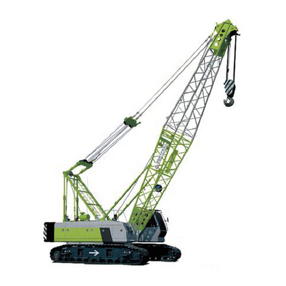
CRAWLER CRANE
OPERATOR'S MANUAL
Zoomlion Heavy Industry Science and Technology Co., Ltd
Add: Quantang Industrial Park, No. 1636, 2nd Yuanda Road, Economic and
Technological Development Zone, Changsha, Hunan Province, China.
PC: 410131
www.zoomlion.com
Zoomlion Heavy Industry Science and Technology Co., Ltd.
Advertisement
Table of Contents

Related Manuals for Zoomlion ZCC1100H


Summary of Contents for Zoomlion ZCC1100H
- Page 1 Vision creates future CRAWLER CRANE OPERATOR’S MANUAL Zoomlion Heavy Industry Science and Technology Co., Ltd Add: Quantang Industrial Park, No. 1636, 2nd Yuanda Road, Economic and Technological Development Zone, Changsha, Hunan Province, China. PC: 410131 www.zoomlion.com Zoomlion Heavy Industry Science and Technology Co., Ltd.
- Page 3 ZCC1100H Crawler Crane Operator’s Manual Edition 1 5, 2014...
-
Page 5: To Users
Under the copyright laws, this manual may not be copied, photocopied, reproduced, translated, or reduced to any electronic medium or machine readable form, in whole or part, without the prior written consent of Zoomlion Heavy Industry Science and Technology Co., Ltd. -
Page 7: Table Of Contents
Operator’s Manual for Crawler Crane Operator’s Manual for Crawler Crane Contents To Users ............................I Safety Instructions ........................II Chapter 1 Safety 1.1 Important instructions ....................1-1 1.1.1 Notes ....................... 1-1 1.1.2 Alarms and warnings ..................1-1 1.2 Safety tips ........................1-2 1.2.1 Safety precautions ................... - Page 8 Operator’s Manual for Crawler Crane 2.3.4 Overall dimensions..................2-12 2.4 Technical data ......................2-13 2.4.1 Main technical parameter ................2-13 2.4.2 Specification of load hook and selection of rope reeving ......... 2-15 2.4.3 Performance of wire rope and winch............... 2-15 2.4.4 Lifting height ....................
- Page 9 Operator’s Manual for Crawler Crane Operator’s Manual for Crawler Crane 3.4 Requirements for operating site ................. 3-28 3.4.1 Slopes and trenches..................3-28 3.4.2 Permissible ground pressure ................3-29 3.4.3 Travel on level ground or slope without a load ..........3-30 3.4.4 Travel on level ground or slope with a load .............
- Page 10 Operator’s Manual for Crawler Crane 4.1.6 Control panel on the roof of operator’s cab ............4-9 4.2 Instruction for digital display system ................4-12 4.2.1 Load moment limiter ..................4-12 4.2.2 Electrical system .................... 4-13 4.3 Startup of the crane ....................4-19 4.3.1 Adjustment of crane operator’s seat ...............
- Page 11 Operator’s Manual for Crawler Crane Operator’s Manual for Crawler Crane Chapter 5 Assembly and Dismantling 5.1 Safety-technical notes ....................5-1 5.1.1 Notes on assembly ................... 5-1 5.1.2 Checking safety measures ................5-1 5.1.3 Checking wire rope, load hook, rope pulley and anchoring rod ......5-3 5.2 Assembly of basic machine ..................
-
Page 13: Chapter 1 Safety
履带起重机操作手册 Operator’s Manual for Crawler Crane 第一章 安全操作说明 Chapter 1 Safety... -
Page 15: Important Instructions
Make sure the replacement parts include warning or instruction labels where necessary. CAUTION (1) Follow the warnings and instructions for the sake of personal safety. (2) For the position of warnings and instruction labels, please see chapter 3 "Safety Guidelines". ZCC1100H Crawler Crane... -
Page 16: Safety Tips
For reasons of safety, long hair must be tied back or otherwise secured. Garments must be close fitting and no jewellery such as rings may be worn. Correctly wear personnel protective equipment. Recommended personnel protective equipment includes: ZCC1100H Crawler Crane... -
Page 17: Organizational Safety Measures
Maintenance work must only be undertaken by suitable qualified engineers with specialist knowledge of this crane. Work on the hydraulic system must be carried out only by personnel with special knowledge and experience of hydraulic equipment. ZCC1100H Crawler Crane... -
Page 18: Safety Advice Regarding Specific Operation Phases
The electrical equipment of the crane must be inspected at regular intervals. Defects such as loose connections, scorched or otherwise damaged cables must be rectified immediately. Use only original fuses with the specified current rating. Switch off the machine immediately if trouble occurs in the electrical system. ZCC1100H Crawler Crane... -
Page 19: Gas, Dust, Steam, Smoke And Noise
Depressurize all system components and pressure pipes (such as hydraulic system, compressed air system) to be removed in accordance with the specific instructions for the unit concerned before carrying out any repair work. ZCC1100H Crawler Crane... - Page 20 Only fit replacement components of a type provided by the manufacturer. Always keep hydraulic elements clean. Hydraulic fluid under pressure can penetrate the skin and cause serious injury. Once the fluid is injected under/into the skin, seek medical help immediately. ZCC1100H Crawler Crane...
-
Page 21: Chapter 2 Description Of Crane
履带起重机操作手册 Operator’s Manual for Crawler Crane 第二章 起重机的描述 Chapter 2 Description of Crane... -
Page 23: Product Model
Operator’s Manual for Crawler Crane Chapter 2 Description of Crane 2.1 Product model 2.1.1 Product name plate and its position Position of product name plate Figure 2-1 Position of product name plate Figure 2-2 Product name plate ZCC1100H Crawler Crane... -
Page 24: Engine Type And Its Manufacturer
Use the crane only when it is in full working order and only for its intended use, paying attention at all times to safety and potential hazards, and in observance of the Operator’s Manual and Maintenance Manual. CAUTION Have any malfunctions which might impair safety rectified immediately. ZCC1100H Crawler Crane... - Page 25 ZCC1100H Crawler Crane...
- Page 26 CAUTION Some components (for example, wire rope, pulley and bearing) are not designed for the entire service life of the crane, but must be replaced after a certain amount of time. ZCC1100H Crawler Crane...
-
Page 27: Terminology
Operator’s Manual for Crawler Crane 2.2 Terminology 2.2.1 Crane modes 2.2.1.1 Working mode The boom configurations of ZCC1100H crawler crane in working mode are shown in the table 2-2. Table 2-2 Boom configurations of ZCC1100H crawler crane in working mode Configuration... - Page 28 2.2.1.2 Assembly mode There exists an assembly mode for ZCC1100H crawler crane, which is used for crane self-assembly and dismantling during crane conversion. During crane self-assembly and dismantling operation, mounting cylinder is used to lift a load. The maximum lifting capacity of mounting cylinder is 26460lb (12t).
- Page 29 Whenever using mounting cylinder on the boom to lift the load, be sure to make the crane in assembly mode. According to actual requirements, there are five working modes and an assembly mode available for this crawler crane. For the details, please refer to relevant documents of load moment limiter. ZCC1100H Crawler Crane...
-
Page 30: Description Of Main Components
Names of the components Rear counterweight Slewing mechanism Counterweight lifting cylinder Fuel tank Hydraulic oil tank Hoisting winch 1 Hoisting winch 2 Engine Main valve Hoisting winch 3 (optional) Battery box Derricking winch Tool box Counterweight assembly Operator’s cab ZCC1100H Crawler Crane... - Page 31 Names of the components Drive sprocket Vertical support (optional) Crawler carrier Support plate (optional) Track roller Support cylinder (optional) Track carrier roller Central counterweight Track pad Undercarriage central section Driven sprocket Horizontal cylinder Folding bracket Undercarriage control lever ZCC1100H Crawler Crane...
-
Page 32: Product Description
7872’ (2400m). For details, please consult the local service provider of the engine or technological department of crawler crane of Zoomlion. 2-10 ZCC1100H Crawler Crane... - Page 33 All-steel construction cab with safety glass; Fitted with operator’s seat, control and operating instruments Safety equipment Angle indicator, load moment limiter, hoisting limiter, support cylinder locking device, safety valves, derricking limiter and so on Electrical system 24v DC, negative ground ZCC1100H Crawler Crane 2-11...
-
Page 34: Overall Dimensions
Operator’s Manual for Crawler Crane 2.3.4 Overall dimensions Unit: ft (mm) 30° ~82.5° 3'3" (1000) 2'7" 17'10" (800) (5440) 20'10" Extended/retracted 16'5"/11'2" (6340) Extended/retracted (5000/3400) R15'5" (4700) Figure 2-7 Overall dimensions of the crane 2-12 ZCC1100H Crawler Crane... -
Page 35: Technical Data
Operator’s Manual for Crawler Crane Operator’s Manual for Crawler Crane 2.4 Technical data 2.4.1 Main technical parameter Table 2-5 Technical parameter of ZCC1100H crawler crane Item Unit Value Remarks 110/10’6” (100/3.2) Max. lifting capacity/radius US Tons / ft (t/m) Max. lifting capacity of fixed jib US Tons (t) 8.8 (8) - Page 36 2100rpm. Max. transport weight of basic machine in the table refers to the weight of basic machine whose hoisting winches 1 and 2 have free-fall functions. 2-14 ZCC1100H Crawler Crane...
-
Page 37: Specification Of Load Hook And Selection Of Rope Reeving
2.4.2 Specification of load hook and selection of rope reeving There are four types of load hooks available for ZCC1100H crawler crane. In actual operation, choose appropriate load hook according to the weight of load and the length of boom. - Page 38 95 (29) 301 (92) 149 (45.6) 34.6 (15.7) 23.8 (10.8) 98 (30) 324 (99) 160 (49.0) 32.4 (14.7) 22.2 (10.1) 104 (32) 347 (106) 172 (52.5) 30.4 (13.8) 20.9 (9.5) 111 (34) 373 (114) 183 (55.9) 2-16 ZCC1100H Crawler Crane...
- Page 39 131 (40) 393 (120) 150 (46) 20.9 (9.5) 17.8 (8.1) 141 (43) 419 (128) 164 (50) WARNING If rated single rope force on the corresponding layer is exceeded, the service life of winch reducer will reduce obviously. ZCC1100H Crawler Crane 2-17...
-
Page 40: Lifting Height
Figure 2-8 Lifting height on main boom CAUTION (1) The X-axis indicates the working radius in ft(m), and the Y-axis indicates the lifting height in ft(m). (2) The boom lifting height curve is drawn without considering boom deflection. 2-18 ZCC1100H Crawler Crane... - Page 41 Figure 2-9 Lifting height on fixed jib (fixed jib angle=10° ) CAUTION (1) The X-axis indicates the working radius in ft (m), and the Y-axis indicates the lifting height in ft (m). (2) The boom lifting height curve is drawn without considering boom deflection. ZCC1100H Crawler Crane 2-19...
- Page 42 Figure 2-10 Lifting height on fixed jib (fixed jib angle=30° ) CAUTION (1) The X-axis indicates the working radius in ft (m), and the Y-axis indicates the lifting height in ft (m). (2) The boom lifting height curve is drawn without considering boom deflection. 2-20 ZCC1100H Crawler Crane...
-
Page 43: Lifting Capacity Chart
The value mentioned in the chart is the lifting capacity when the crane is working with 61740Lbs (28t) rear counterweight and 22050lbs (10t) central counterweight in 360° range. The crawler carriers of the crane are extended completely. The sign “*/*” in the chart indicates “lifting capacity/radius”. ZCC1100H Crawler Crane 2-21... - Page 44 (10.2) (10.1) (10.0) (9.9) (9.8) (21.3) 20.1/75 18.5 18.3 18.1 17.9 (24.4) (9.1/22.9) (8.4) (8.3) (8.2) (8.1) (24.4) 15.7 15.4 15.2 (27.4) (7.1) (7.0) (6.9) (27.4) 13.2 13.0 (30.5) (6.0) (5.9) (30.5) 11.2 (33.5) (5.1) (33.5) 2-22 ZCC1100H Crawler Crane...
- Page 45 (42.7) (3.3/41.1) (3.0) (2.9) (2.8) (2.7) (2.6) (2.5) (2.3) (42.7) (45.7) (2.5) (2.4) (2.3) (2.2) (2.1) (1.9) (45.7) (48.8) (2.1) (1.8) (1.7) (1.6) (48.8) (51.8) (1.7) (1.5) (1.4) (1.3) (51.8) 2.9/175 (54.9) (1.3/53.4) (1.1) (1.0) (54.9) ZCC1100H Crawler Crane 2-23...
- Page 46 (4) The value in the chart is the lifting capacity of the crane without a tip boom. When main boom is fitted with tip boom, the lifting capacity must include the weight of main load hook, wire rope, lifting device as well as the weight of tip boom, auxiliary hook, and wire rope. 2-24 ZCC1100H Crawler Crane...
- Page 47 16.5 16.3 (21.3) (8.4) (8.4) (7.9) (7.5) (7.4) (21.3) 14.8 14.8 13.9 13.9 12.8 (24.4) (6.7) (6.7) (6.3) (6.3) (5.9) (5.8) (24.4) 12.3 12.1 11.5 11.2 10.4 10.4 (27.4) (5.6) (5.5) (5.2) (5.1) (4.7) (4.7) (27.4) ZCC1100H Crawler Crane 2-25...
- Page 48 14.6 14.6 13.9 13.7 12.8 12.6 (24.4) (6.6) (6.6) (6.3) (6.2) (5.8) (5.7) (24.4) 12.1 11.9 11.2 11.2 10.4 10.1 (27.4) (5.5) (5.4) (5.1) (5.1) (4.7) (4.6) (27.4) (30.5) (4.5) (4.5) (4.1) (4.1) (3.7) (3.7) (30.5) 2-26 ZCC1100H Crawler Crane...
- Page 49 13.4 12.8 12.3 (24.4) (6.5) (6.5) (6.2) (6.1) (5.8) (5.6) (24.4) 11.9 11.9 11.0 11.0 10.1 (27.4) (5.4) (5.4) (4.6) (4.5) (27.4) (30.5) (4.4) (4.4) (3.6) (3.6) (30.5) (33.5) (3.6) (3.6) (3.3) (3.2) (2.8) (2.8) (33.5) ZCC1100H Crawler Crane 2-27...
- Page 50 11.7 11.7 10.8 10.8 (27.4) (5.3) (5.3) (4.9) (4.9) (4.5) (4.4) (27.4) (30.5) (4.3) (4.3) (3.9) (3.9) (3.5) (3.5) (30.5) (33.5) (3.5) (3.5) (3.2) (3.1) (2.8) (2.7) (33.5) (35.1) (3.1) (3.1) (2.8) (2.8) (2.4) (2.4) (35.1) 2-28 ZCC1100H Crawler Crane...
- Page 51 (5.2) (4.8) (4.8) (4.4) (4.3) (27.4) (30.5) (4.2) (4.2) (3.9) (3.8) (3.5) (3.4) (30.5) (33.5) (3.4) (3.4) (3.1) (3.1) (2.7) (2.6) (33.5) (36.6) (2.7) (2.7) (2.4) (2.4) (36.6) (38.1) (2.4) (2.4) (2.1) (2.1) (1.7) (1.7) (38.1) ZCC1100H Crawler Crane 2-29...
- Page 52 (4.1) (3.8) (3.7) (3.4) (3.3) (30.5) (33.5) (3.3) (3.3) (2.6) (2.5) (33.5) (36.6) (2.6) (2.6) (2.3) (2.3) (1.9) (1.9) (36.6) (39.6) (2.2) (2.2) (1.8) (1.8) (1.4) (1.4) (39.6) (41.1) (1.9) (1.9) (1.5) (1.5) (1.2) (1.1) (41.1) 2-30 ZCC1100H Crawler Crane...
- Page 53 (30.5) (3.7) (3.6) (3.3) (3.2) (30.5) (33.5) (3.2) (3.2) (2.9) (2.9) (2.5) (2.5) (33.5) (36.6) (2.6) (2.5) (2.2) (2.2) (1.8) (1.8) (36.6) (39.6) (2.1) (2.1) (1.7) (1.7) (1.4) (1.3) (39.6) (42.7) (1.6) (1.6) (1.2) (1.2) (42.7) ZCC1100H Crawler Crane 2-31...
- Page 54 (3.1) (30.5) (33.5) (3.1) (3.1) (2.8) (2.8) (2.4) (2.4) (33.5) (36.6) (2.5) (2.4) (2.1) (2.1) (1.8) (1.7) (36.6) (39.6) (1.9) (1.9) (1.5) (1.5) (1.2) (1.1) (39.6) (42.7) (1.5) (1.5) (1.2) (1.1) (42.7) (45.7) (1.1) (1.1) (45.7) 2-32 ZCC1100H Crawler Crane...
- Page 55 (3) Do not lift a load in the area which is not in the lifting capacity range, otherwise the crane may topple over or be damaged. ZCC1100H Crawler Crane 2-33...
- Page 56 (5) The value in the chart is the maximum lifting capacity of the crane, including the weight of lifting device, hook, wire rope at the end of hook and so on. (6) The crawler carriers are extended completely. The hook on the fixed jib is nearest to the jib head. 2-34 ZCC1100H Crawler Crane...
- Page 57 (21.3) 17.6 16.1 15.9 15.6 15.3 (24.4) (7.3) (7.2) (7.1) (24.4) 14.3/85 13.2 12.8 12.8 (27.4) (6.5/25.9) (5.8) (5.8) (27.4) 11.9/95 10.6 10.6 (30.5) (5.4/29) (4.8) (4.8) (30.5) 9.3/105 (33.5) (4.2/32) (33.5) 7.9/115 (36.6) (3.6/35) (36.6) ZCC1100H Crawler Crane 2-35...
- Page 58 (according to the standard ASME/ANSI B30.5). The value can not exceed 75% of the overturning lifting capacity when the crane is on firm and flat ground. 2-36 ZCC1100H Crawler Crane...
- Page 59 (7) Choose the type of hook on the main boom before the system is switched to S-3 configuration. (8) The crawler carriers are extended completely. The hook on the main boom is nearest to the main boom head. ZCC1100H Crawler Crane 2-37...
- Page 60 11.0 10.6 (4.8) (2.9) (30.5) (5.6) (5.6) (5.8) (30.5) 10.6 11.0 10.8 (4.9) (4.4) (2.8) (33.5) (4.8) (33.5) (4.1) (2.6) (36.6) (4.3) (4.4) (36.6) (39.6) (3.8) (3.5) (2.5) (39.6) (42.7) (3.2) (2.4) (42.7) (45.7) (2.3) (45.7) 2-38 ZCC1100H Crawler Crane...
- Page 61 10.8 10.8 10.1 (4.9) (4.6) (2.9) (33.5) (4.7) (4.8) (4.9) (33.5) (4.3) (4.2) (2.7) (36.6) (4.1) (4.2) (36.6) (39.6) (3.6) (3.7) (3.7) (2.6) (39.6) (42.7) (3.2) (3.2) (2.5) (42.7) (45.7) (2.9) (2.4) (45.7) (48.8) (2.2) (48.8) ZCC1100H Crawler Crane 2-39...
- Page 62 10.1 (33.5) (4.6) (4.7) (4.7) (4.9) (4.6) (2.9) (33.5) (36.6) (3.9) (4.1) (4.2) (4.2) (2.8) (36.6) (3.7) (2.7) (39.6) (3.5) (3.7) (39.6) (2.5) (42.7) (3.1) (3.2) (3.2) (42.7) (2.5) (45.7) (2.8) (45.7) (48.8) (2.4) (2.4) (48.8) 2-40 ZCC1100H Crawler Crane...
- Page 63 (4.6) (33.5) (36.6) (3.8) (3.9) (4.1) (4.2) (2.8) (36.6) (39.6) (3.3) (3.4) (3.5) (3.6) (3.5) (2.7) (39.6) (2.5) (42.7) (3.1) (3.1) (42.7) (2.5) (45.7) (2.6) (2.7) (2.7) (45.7) (2.4) (48.8) (2.4) (48.8) (51.8) (2.1) (2.1) (51.8) ZCC1100H Crawler Crane 2-41...
- Page 64 (3.8) (3.9) (4.1) (36.6) (3.4) (2.8) (39.6) (3.2) (3.2) (3.3) (3.5) (39.6) (2.6) (42.7) (2.7) (2.7) (2.9) (42.7) (45.7) (2.5) (2.6) (2.6) (2.5) (45.7) (48.8) (2.1) (2.2) (2.3) (2.4) (48.8) (51.8) (1.9) (51.8) (54.9) (1.7) (54.9) 2-42 ZCC1100H Crawler Crane...
- Page 65 (3.4) (3.4) (2.9) (39.6) (42.7) (2.6) (2.7) (2.8) (2.9) (2.9) (2.8) (42.7) (2.6) (45.7) (2.4) (2.5) (2.5) (45.7) (48.8) (2.1) (2.1) (2.3) (48.8) (51.8) (1.7) (1.8) (1.8) (51.8) (54.9) (1.6) (1.6) (54.9) (57.9) (1.3) (1.4) (57.9) ZCC1100H Crawler Crane 2-43...
- Page 66 (39.6) (42.7) (2.5) (2.6) (2.6) (2.8) (2.7) (2.8) (42.7) (2.6) (45.7) (2.1) (2.2) (2.2) (2.4) (2.3) (45.7) (48.8) (1.7) (1.8) (1.9) (2.2) (48.8) (51.8) (1.7) (1.7) (1.9) (51.8) (54.9) (1.4) (1.6) (54.9) (57.9) (1.2) (1.3) (57.9) 2-44 ZCC1100H Crawler Crane...
- Page 67 (2.4) (2.4) (2.6) (2.7) (2.7) (2.8) (42.7) (45.7) (2.1) (2.2) (2.3) (2.3) (2.5) (45.7) (48.8) (1.6) (1.7) (1.8) (1.9) (1.9) (2.1) (48.8) (51.8) (1.3) (1.4) (1.5) (1.6) (1.6) (1.8) (51.8) (54.9) (1.2) (1.3) (1.3) (1.5) (54.9) ZCC1100H Crawler Crane 2-45...
- Page 68 (according to the standard ASME/ANSI B30.5). The value can not exceed 75% of the overturning lifting capacity when the crane is on firm and flat ground. 2-46 ZCC1100H Crawler Crane...
- Page 69 (5) The value in the chart is the maximum lifting capacity of the crane, including the weight of lifting device, hook, wire rope at the end of hook and so on. (6) The crawler carriers of the crane are extended completely. ZCC1100H Crawler Crane 2-47...
- Page 70 10.8 10.8 11.5 11.0 10.6 (4.8) (2.9) (30.5) (4.9) (4.9) (5.2) (30.5) (2.8) (33.5) (4.1) (4.4) (4.3) (3.9) (33.5) (2.6) (36.6) (3.7) (3.8) (3.4) (36.6) (39.6) (3.2) (2.5) (39.6) (42.7) (2.7) (2.4) (42.7) (45.7) (2.3) (45.7) 2-48 ZCC1100H Crawler Crane...
- Page 71 (4.9) (4.9) (4.8) (4.9) (30.5) (33.5) (4.1) (4.3) (4.3) (4.1) (2.9) (33.5) (36.6) (3.4) (3.6) (3.7) (3.7) (2.7) (36.6) (2.6) (39.6) (3.1) (3.2) (39.6) (2.5) (42.7) (2.6) (2.7) (42.7) (2.4) (45.7) (2.4) (45.7) (48.8) (2.2) (48.8) ZCC1100H Crawler Crane 2-49...
- Page 72 (4.5) (30.5) (33.5) (3.9) (4.1) (4.3) (4.1) (2.9) (33.5) (36.6) (3.2) (3.3) (3.5) (3.6) (3.7) (2.8) (36.6) (2.7) (39.6) (2.9) (3.1) (3.2) (39.6) (2.5) (42.7) (2.5) (2.6) (2.7) (42.7) (45.7) (2.3) (45.7) (48.8) (1.9) (1.9) (48.8) 2-50 ZCC1100H Crawler Crane...
- Page 73 (3.8) (4.1) (33.5) (2.8) (36.6) (3.1) (3.2) (3.4) (3.5) (3.6) (36.6) (2.7) (39.6) (2.6) (2.7) (2.9) (2.9) (39.6) (42.7) (2.4) (2.5) (2.5) (2.5) (42.7) (45.7) (2.1) (2.1) (45.7) (48.8) (1.8) (1.9) (48.8) (51.8) (1.5) (1.6) (51.8) ZCC1100H Crawler Crane 2-51...
- Page 74 (3.1) (3.3) (3.5) (3.4) (2.9) (36.6) (39.6) (2.5) (2.5) (2.7) (2.9) (2.8) (2.8) (39.6) (42.7) (2.3) (2.4) (2.4) (2.6) (42.7) (45.7) (1.9) (45.7) (48.8) (1.5) (1.6) (1.7) (1.9) (48.8) (51.8) (1.3) (1.5) (51.8) (54.9) (1.2) (54.9) 2-52 ZCC1100H Crawler Crane...
- Page 75 (2.6) (2.8) (2.8) (39.6) (2.3) (42.7) (1.9) (2.2) (2.3) (2.3) (42.7) (45.7) (1.8) (1.9) (1.9) (2.1) (45.7) (48.8) (1.4) (1.5) (1.5) (1.8) (48.8) (51.8) (1.1) (1.2) (1.2) (1.5) (51.8) (54.9) (1.1) (54.9) (57.9) (0.7) (0.8) (57.9) ZCC1100H Crawler Crane 2-53...
- Page 76 (2.9) (39.6) (42.7) (1.8) (1.9) (2.2) (2.1) (2.3) (42.7) (45.7) (1.4) (1.5) (1.6) (1.8) (1.7) (2.1) (45.7) (48.8) (1.1) (1.3) (1.4) (1.4) (1.7) (48.8) (51.8) (1.1) (1.1) (1.4) (51.8) (54.9) (0.8) (1.1) (54.9) (57.9) (0.7) (57.9) 2-54 ZCC1100H Crawler Crane...
- Page 77 (2.2) (2.4) (2.6) (2.5) (39.6) (2.3) (42.7) (1.7) (1.7) (2.1) (2.1) (42.7) (45.7) (1.3) (1.4) (1.6) (1.7) (1.7) (45.7) (48.8) (0.9) (1.2) (1.3) (1.3) (1.6) (48.8) (51.8) (0.7) (0.9) (1.3) (51.8) (54.9) (0.7) (0.7) (0.9) (54.9) ZCC1100H Crawler Crane 2-55...
- Page 78 (according to the standard ASME/ANSI B30.5). The value can not exceed 75% of the overturning lifting capacity when the crane is on firm and flat ground. 2-56 ZCC1100H Crawler Crane...
-
Page 79: Lifting Capacity In Assembly Mode
(4) The value in the above chart is the maximum lifting capacity of the cylinder, including the weight of lifting device, cylinder and so on. ZCC1100H Crawler Crane 2-57... -
Page 81: Chapter 3 Safety Guidelines
履带起重机操作手册 Operator’s Manual for Crawler Crane 第三章 安全准则 Chapter 3 Safety Guidelines... -
Page 83: Operational Planning
(2) If the crane operator does not possess all necessary and required information, it may prove impossible to carry out the intended work and accidents may be the result! ZCC1100H Crawler Crane... -
Page 84: Correct Use Of The Crane
10) Not using the specified safety equipment when operating the crane, such as load moment limiter, hoisting limiter etc; 11) Not complying with the lifting capacity chart; 12) Installing unauthorized parts without the written consent from the manufacturer; 13) Operating the crane in dangerous area. ZCC1100H Crawler Crane... -
Page 85: Responsibility Of Relevant Personnel
After finishing the operation, put the igniting key in the off position, take down the cab key and engine key, and lock the door to prevent unauthorized person from operating the crane. 10) Keep the windshield, platform and step clean and stacking of sundries is not allowed. ZCC1100H Crawler Crane... -
Page 86: Work Area
No articles is allowed to put on the thoroughfare, such as clothes, protecting device, personal article, etc Snow, ice or other obstacles should not be put in the entrance of the cab. Keep all the windows and rearview mirrors clean without condensed water and ice. 安 全 准 则 ZCC1100H Crawler Crane... -
Page 87: Safety Technical Notes
Quick braking during free fall process (optional); Diagonal pulling and slewing of the load to be lifted which is still in contact with the ground. Loose wire rope formations on the winch; Overloading or improperly attaching the load; ZCC1100H Crawler Crane... -
Page 88: Safety Instructions For The Rigger
Be able to use audio equipment (such as interphone) safely to send out oral order exactly and clearly; Be capable of controlling and conducting the crane to move the load safely; Make sure that only authorized personnel are allowed to carry out the work. ZCC1100H Crawler Crane... -
Page 89: Safety Instructions For The Signalman
All the workers must know about the content of the task and working sequence; Check whether dangerous situations occur during operation of the machine, and inform crane operator and signalman of the unsafe factors such as high-voltage power line, unauthorized persons and equipment, and poor ground conditions. ZCC1100H Crawler Crane... -
Page 90: Electromagnetic Influences
(2) Danger of burns or inflammation due to too high temperature. (3) Spark or electric arc formation. In any case, before working with the crane near transmitters, contact Zoomlion representatives. In addition, consult a high - frequency specialist. The whole crane must be “totally” grounded. Check visually or with a simple tester to ensure that the ladder, cab and cable pulleys are grounded. -
Page 91: Safety Signs
(i.e. near the operator’s cab) is shown in the figure 3-2. As to the description of safety signs, please see the table 3-1. 安 全 准 则 Figure 3-1 Arrangement of safety signs on one side of the crane (near the ladder) ZCC1100H Crawler Crane... - Page 92 Figure 3-2 Arrangement of safety signs on the other side of the crane (near the operator’s cab) Table 3-1 Description of safety signs near the ladder and operator’s cab Figure Figure Safety signs Description Risk of burn 3-10 ZCC1100H Crawler Crane...
- Page 93 安 opened. 全 准 则 Standard hand signal controlling crane operation. For the details, please refer to section 10 of chapter 3. Required safety distance when working near the high-voltage power line. ZCC1100H Crawler Crane 3-11...
- Page 94 Safety signs Description Open flame prohibited. Do not stand under the jib during assembling 安 全 disassembling 准 process. 则 No standing under the boom. Keep away 9,16 5,12 from moving parts. No access for unauthorized personnel. 3-12 ZCC1100H Crawler Crane...
- Page 95 Table 3-1 Description of safety signs near the ladder and operator’s cab Figure Figure Safety signs Description Risk of falling. Keep off folding 12,14 brackets/additional supports. 安 全 准 则 Keep away from 13,15 moving parts. ZCC1100H Crawler Crane 3-13...
- Page 96 Figure 3-3 Arrangement of safety signs on the slewing table 安 Table 3-2 Description of safety signs on the slewing table 全 准 则 Safety signs Description Step off. Access prohibited. Keep away from moving 3,4,5 parts. Risk of burn. 3-14 ZCC1100H Crawler Crane...
- Page 97 Table 3-3 Description of safety signs in the front of slewing table 安 全 Safety signs Description 准 则 Risk of falling. Never climb the machine during operation. Keep clear of swinging area to prevent serious body injury. Pull out the fixed pin spindle before slewing. ZCC1100H Crawler Crane 3-15...
- Page 98 Arrangement of safety signs on the derricking traveling block is shown in the figure 3-6, and the description of safety signs is shown in the table 3-5. Figure 3-6 Arrangement of safety signs on the derricking traveling block 3-16 ZCC1100H Crawler Crane...
-
Page 99: The Potential Dangers Existing In Crane Operation
Always wear safety goggles. Safety instructions and preventive measures to avoid mechanical hazards: Only remove protective hoods and safety covers – When the machine has come to a standstill or – Is secured against an accident restart. ZCC1100H Crawler Crane 3-17... -
Page 100: Injuries Due To Hydraulic Energy
Penetrates clothing and the surface of the skin, Enters the flesh and causes tissue damage And/ or gets into the bloodstream. First aid for injuries: Bandage injured area(s) with anti-bacterial bandage and seek medical attention at once. 3-18 ZCC1100H Crawler Crane... -
Page 101: Scald
Follow these safety instructions: Always disconnect battery leads before doing any maintenance to the electrical system. When working with or near a battery, the operator must always wear safety goggles and protective gloves. ZCC1100H Crawler Crane 3-19... -
Page 102: Risk Of Fire And Explosion
Always refuel the equipment in a well ventilated area. Before filling the fuel tank or the hydraulic tank, the following must be turned off: 1) The engine; 2) The cab’s heater; 3) The auxiliary heating. 3-20 ZCC1100H Crawler Crane... - Page 103 WARNING (1) When refueling the equipment, an explosive mixture of gases may be created. (2) Escaping diesel fuel or hydraulic oil may ignite if it comes into contact with a hot surface. ZCC1100H Crawler Crane 3-21...
-
Page 104: Risk Of Poisoning And Asphyxiation
(2) When the equipment is used in areas where there are hazardous materials, such as toxic waste dumps, it is possible for the operator to come into contact with materials and gases that are injurious to health. 3-22 ZCC1100H Crawler Crane... -
Page 105: Endangering The Environment
Use separate containers to collect and dispose of the different fuels and lubricants. CAUTION Fuels, hydraulic oil, cleaning agents or similar liquids can damage or pollute the environment if they get into the ground, into river or into the sewer system. 安 全 准 则 ZCC1100H Crawler Crane 3-23... -
Page 106: Slings
Determine the weight of the load and choose appropriate equipment. CAUTION The strength and the integrity of the rigging hardware is another fundamental part of the safe lifting operations. To maintain rigging hardware and its components, frequent and periodic inspections are required. 3-24 ZCC1100H Crawler Crane... -
Page 107: Slings Introduction
Make sure that the load is not clamped, or bolted to the floor. Guard against shock loading by pulling the slack sling straight slowly. Apply power cautiously so as to prevent jerking at the beginning of the lift, and accelerate or decelerate slowly. ZCC1100H Crawler Crane 3-25... -
Page 108: Sling Safety Guide
The safest method for a rigger to control a load attached onto the hook is with a tagline (refer to the figure 3-7): Taglines are used to control load spin. Keep the tagline away from the center of gravity. Figure 3-7 Tagline diagram 3-26 ZCC1100H Crawler Crane... -
Page 109: Load Center Of Gravity
Finding the center of gravity of irregularly-shaped objects can be more difficult, but it is necessary. A load will always hang from its attachment point through the center of gravity. It is important to visualize this before making a lift. ZCC1100H Crawler Crane 3-27... -
Page 110: Requirements For Operating Site
Hard or natural soil = 1×depth of trench (Al = 1×T). DANGER If a safe distance is not maintained, the slope or trench must be firmly filled. Otherwise, there is a danger that the edge of the slope or trench will collapse. 3-28 ZCC1100H Crawler Crane... -
Page 111: Permissible Ground Pressure
Asphalt 5-15 Concrete Concrete group B I 50-250 Concrete group B II 350-550 CAUTION If there is any doubt about the load-bearing capacity of the ground at the operating site, soil test should be carried out. ZCC1100H Crawler Crane 3-29... -
Page 112: Travel On Level Ground Or Slope Without A Load
The maximum climbing ability of a crawler crane is limited by the following condition: The center of gravity of the whole crane; The friction coefficient between roadway and track pad; The transfer between the horizontal and the inclined. 3-30 ZCC1100H Crawler Crane... - Page 113 (7) Travel slowly, and perform all acceleration and deceleration motions with utmost caution. (8) The transfer from the horizontal to the incline and from the incline to the horizontal must be made very evenly. The change of gradient must be continuous. 安 全 准 则 ZCC1100H Crawler Crane 3-31...
-
Page 114: Operation Weather
Thoroughly check the equipment, check for any damaged cables or lines for leaks. Check the entire control system. Slowly move the slewing gear and listen for unusual noises in the rotary connection, especially in the slewing ring. 3-32 ZCC1100H Crawler Crane... -
Page 115: Electrical Safety
Any one contacting with the machine may get an electric shock. WARNING Qualified electrician can use proper testing tools to check protective measures or decide whether the electricity can be supplied by comprehensive power supply network according to VDE. ZCC1100H Crawler Crane 3-33... -
Page 116: Underground Cables
Do not start work until you have obtained all the approvals from the utility companies and the cable users. The equipment operator must obtain all relevant information about the exact location of all underground cables before starting work. These plans must be readily accessible at the construction site. 3-34 ZCC1100H Crawler Crane... -
Page 117: Notes In Connection With Gas Pipes
Every source of ignition, such as On /Off switches on electrical equipment or the turning on of a light, can trigger an explosion. Corrosion can cause leaks to form within 5 -10 years with minor damage to the casings of metal gas pipes. ZCC1100H Crawler Crane 3-35... -
Page 118: Measures Adopted If A Gas Pipe Is Damaged And The Gas Escapes, Or A Leak Is Suspected
(2) A gas fire that has already been extinguished can flare up again if more gas escape and break out in an unexpected spot. (3) Precautions in the event of a gas fire: Inform the local fire department of the fire. 3-36 ZCC1100H Crawler Crane... -
Page 119: Notes In Connection With Underground Electric Cables
Then drive the machine out of the danger area. Only stop the machine once the distance from the fault location is – At least17ft (5 m ) in the case of a low-voltage cable (lower than 1000V), ZCC1100H Crawler Crane 3-37... - Page 120 Only leave the driver’s cab if you have reliable confirmation that the underground cable has been switched off. DANGER 安 全 Even an underground cable that has been switched off can be switched on again 准 则 manually, or by automatic safety devices, for fault detection purposes. 3-38 ZCC1100H Crawler Crane...
-
Page 121: Checking Safety Measures
Check whether there are obstacles which will hinder required crane operation. CAUTION The crane operation belongs to dangerous operation; so much attention should be given to the working condition of the crane before and during crane operation. ZCC1100H Crawler Crane 3-39... -
Page 122: Crane Operation With A Load
61740 lb (28 t) and that of central counterweight is 22050lb (10 t). DANGER If the counterweight is not installed properly according to the lifting capacity chart, there is a danger of the crane toppling over. 3-40 ZCC1100H Crawler Crane... -
Page 123: Crane Operation
21m/s when only main boom assembled, and no more than 15m/s when fixed jib is assembled. Please refer to table 3-8 to estimate the wind velocity more accurately. ZCC1100H Crawler Crane 3-41... - Page 124 13.9-17 wind Breaks twigs off trees, walking becomes Gale force wind 17.2-20.6 difficult Minor damage to property(chimney tops Gale 20.8-24.5 and roofing tile are blown off) Trees are uprooted, significant damage to Severe gale 24.7-28.3 property 3-42 ZCC1100H Crawler Crane...
- Page 125 安 全 准 则 It is forbidden to lift load over people. It is forbidden to lift the load when someone stands on it. Overloading operation lifting staggered load is prohibited. Never pull load obliquely. ZCC1100H Crawler Crane 3-43...
- Page 126 The brake of hoisting winch can not be adjusted when the crane is lifting a load. 3-44 ZCC1100H Crawler Crane...
- Page 127 When actual load reaches 90% of the rated one, the load moment limiter will sound an alarm, to which great attention should be given. Getting on and off the crane should be careful to avoid casualty. ZCC1100H Crawler Crane 3-45...
- Page 128 The crane is overloaded or the weight of load 全 is uncertain 准 则 The load falls down due to bad binding or hanging No protective mat is added between the edges of load and wire rope 3-46 ZCC1100H Crawler Crane...
- Page 129 Keep the windows of crane operator’s cab clean to ensure good visibility; stop crane operation immediately in case of poor visibility; replace the broken window as soon as possible. ZCC1100H Crawler Crane 3-47...
- Page 130 Do not wear loose clothing, scarves, open jackets or open shirt sleeves, and do not wear jewellery (rings, bracelets, earrings or similar). Otherwise, there is serious danger of injury from being pulled into moving machine parts. 3-48 ZCC1100H Crawler Crane...
- Page 131 After the crane is placed well, lift the load hook in a proper position so that it can swing freely. At this time, the operator must stand in front of the crane and observe the following conditions. ZCC1100H Crawler Crane 3-49...
- Page 132 – Check the associated components for functional work. If earthquake occurs when the crane is operated, the following measures should be taken immediately: – Stop work on the crane immediately – Always set down the load and boom frame on the ground. 3-50 ZCC1100H Crawler Crane...
- Page 133 (2) Do not leave the driver’s/operator’s cab. (3) Tell people around the crane not to move and touch the crane. (4) Move the crane out of the dangerous zone. Failure to observe the above points will cause serious accident and damage! ZCC1100H Crawler Crane 3-51...
- Page 134 安 Take precaution measures against frostbite in winter. 全 准 则 WARNING To avoid engine from freezing in winter, drain all cooling water when park the vehicle, if no anti-freeze is added into the cooling water. 3-52 ZCC1100H Crawler Crane...
-
Page 135: Hand Signals For Controlling Crane Operations
The palm body. The extended index palm faces upwards. Description faces forwards. The hand finger points downwards. Wave the hand up makes small, circular The hand makes small, repeatedly. movements. circular movements. Illustration ZCC1100H Crawler Crane 3-53... - Page 136 Extend the fingers to point outwards, move forearm outwards, move forearm Description at the position where the horizontally horizontally load should fall on. repeatedly, fingers repeatedly, fingers pointing at the direction of pointing at the direction of rotation. rotation. Illustration 3-54 ZCC1100H Crawler Crane...
- Page 137 The palm horizontally. The palms Description pointing downwards. faces downwards. Swing face downwards. Swing Place the right arm below the arm to one side of the the arms to both sides of body. the body. Illustration ZCC1100H Crawler Crane 3-55...
- Page 138 (2) Hand signals must first be discussed and mutually agreed upon and clearly executed. Misunderstanding of hand signals may lead to serious accidents. CAUTION In any case, national traffic regulations must always be observed when operating abroad. 3-56 ZCC1100H Crawler Crane...
-
Page 139: Chapter 4 Crane Operation
Operator’s Manual for Crawler Crane 履带起重机操作手册 Chapter 4 Crane Operation 第四章 起重机的操作... -
Page 141: Operating And Control Instruments
Operator’s Manual for Crawler Crane Chapter 4 Crane Operation 4.1 Operating and control instruments 4.1.1 Operator’s cab, overview Figure 4-1 Operator’s cab, overview The arrangement of operating and control instruments in the operator’s cab is shown in the figure 4-1. For detailed information, please see table 4-1. Table 4-1 Description of operating and control instruments Names of Remarks... - Page 142 Operator’s Manual for Crawler Crane Names of Remarks instruments Electrical control box Arrange the electric elements. Arrange the switches for electric elements. (For details, please Operating console see section 4.1.2.) Control the movements of hoisting winches 1 and 3, derricking Right control lever winch and mounting cylinder.
-
Page 143: Operating Console
Operator’s Manual for Crawler Crane 4.1.2 Operating console Set Up Overl o wer Rel e ase On Overroll Release Derrick Release Figure 4-2 Operating console The switches on the operating console are detailed in the table 4-2. Table 4-2 Description of switches on the operating console Names of the Remarks switches... -
Page 144: Control Lever
Operator’s Manual for Crawler Crane Names of the Remarks switches After lowering warning is sent, never reel off hoisting winch. Lowering bypass Turn the switch clockwise and keep it there at this time. When switch the icon appears on the load moment limiter, the hoisting winch can be reeled off. - Page 145 Operator’s Manual for Crawler Crane As shown in the figure 4-3, the left is the operating board for left control lever. It is stuck on the left glass of the cab. The four directions shown on the right means that the control lever can be moved forwards, backwards, leftwards and rightwards.
- Page 146 Operator’s Manual for Crawler Crane 4.1.3.2 Right control lever Front Right Figure 4-4 Illustration of right control lever operation As shown in the figure 4-4, the left is the operating board for right control lever. It is stuck on the left glass of the cab.
-
Page 147: Left Control Panel
Operator’s Manual for Crawler Crane CAUTION The horn can only be actuated in emergency condition to warn the person in the vicinity of the crane. 4.1.4 Left control panel Free Fall Chief H1 Free Fall H3 Free Fall H2 Free Fall Figure 4-5 Left control panel When the crane has free-fall function, the left control panel will be described in the table 4-5. -
Page 148: Right Control Panel
Operator’s Manual for Crawler Crane DANGER (1) If free-fall operation is not finished (i.e. the wind drum does not stop rotating), never set the free-fall switch of corresponding winch to the initial position. (2) When the hoisting winch is controlled by control lever, never switch on any free-fall switches. -
Page 149: Control Panel On The Roof Of Operator's Cab
Operator’s Manual for Crawler Crane CAUTION (1) Before starting the engine each time, first set the ignition key switch in initial position. (2) The engine will be started after automatic preheating when it is cold. Moreover, delay start of the engine is normal. 4.1.6 Control panel on the roof of operator’s cab Control panel Figure 4-7 Position of control panel on the roof of operator’s cab... - Page 150 Operator’s Manual for Crawler Crane Figure 4-8 Switches on the control panel As to the functions of switches on the control panel, refer to figure 4-7. Table 4-7 Description of switches on the control panel Names of switches Functions Washer switch Control the washer Front windshield wiper Control the front windshield wiper...
- Page 151 Operator’s Manual for Crawler Crane Names of switches Functions Turn on this switch to operate mounting cylinder on main Mounting cylinder boom pivot section, and turn off H2 winch switch at the same switch time. Turn on this switch to make the oil cooling fan work when Oil cooling fan switch there is a need to cool the hydraulic oil.
-
Page 152: Instruction For Digital Display System
Operator’s Manual for Crawler Crane 4.2 Instruction for digital display system Figure 4-9 Digital display system The description of digital display system is shown in the table 4-8. Table 4-8 Description of digital display system Names of the Remarks components Display information about crane such as current load, boom LCD screen of load length, boom angle and moment percent. -
Page 153: Electrical System
Operator’s Manual for Crawler Crane 4.2.2 Electrical system The main screen of electrical system is shown in the figure 4-10. Res:0.0 Max:0.6 Free fall alarm +Y:0.0 1500 1000 2000 +X:0.0 0 hour 2500 Voltage 0 rpm 3000 Angle: X:0.0 Y:0.0 Speed 100 Gradient: Y:0.0%... - Page 154 Operator’s Manual for Crawler Crane 4.2.2.1 Alarm functions Figure 4-11 Screen of alarm functions The screen of alarm functions will be described in details in the table 4-9. Table 4-9 Description of alarm functions screen Meaning of the icons Remarks Icon “Engine oil When engine oil pressure is less than 0.06MPa, this icon will pressure”...
- Page 155 Operator’s Manual for Crawler Crane 4.2.2.2 Engine information 1500 1000 2000 0 hour 2500 0 rpm 3000 Speed WaterTEMP Oil Pressure Fule Lever 0.0Bar 0.0% 0℃ Figure 4-12 Screen of engine information The screen of engine information will be described in detail in the table 4-10. Table 4-10 Description of engine information screen Engine information Remarks...
- Page 156 Operator’s Manual for Crawler Crane 4.2.2.3 Monitored additional functions Res:0.0 Max:0.6 Free fall alarm +Y:0.0 +X:0.0 Voltage Angle: Y:0.0 X:0.0 Gradient: X:0.0% Y:0.0% Figure 4-13 Screen of monitored additional functions The screen of monitored additional functions will be described in detail in the table 4-11. Table 4-11 Description of monitored additional functions screen Monitored Remarks...
- Page 157 Operator’s Manual for Crawler Crane 4.2.2.4 Pressure monitoring of hydraulic system 0.0 MPa 0.0 MPa 0.0 MPa Pump 0.0 MPa Derricking 0.0 MPa Slewing 0.0 MPa Control 0.0 MPa Return Oil 0.0 MPa Figure 4-14 Pressure monitoring of hydraulic system The pressure monitoring of hydraulic system will be described in details in the table 4-12.
- Page 158 Operator’s Manual for Crawler Crane 4.2.2.5 Function key area Main Page Enter I\O Watch PAR ADJ PAR Rst Work Status Figure 4-15 Function key area The function key area will be described in the table 4-13. Table 4-13 Description of function key area Function keys Remarks Press this key in any other screen, the system can be...
-
Page 159: Startup Of The Crane
Operator’s Manual for Crawler Crane 4.3 Startup of the crane 4.3.1 Adjustment of crane operator’s seat Vertical adjustment of headrest The height of headrest is adjusted manually with proper strength. Figure 4-16 Adjustment of headrest Adjustment of armrest The height of armrest can be adjusted by the adjusting knobs. Figure 4-17 Adjustment of armrest 4-19... - Page 160 Operator’s Manual for Crawler Crane Horizontal adjustment of seat Pull the lever upwards; Move the seat to required position; Release the lever. Figure 4-18 Horizontal adjustment of seat Adjustment of seat height There are two levers to adjust the seat height. The left lever adjusts the height of the front part of the seat, and the right lever adjusts the height of the rear part of the seat.
-
Page 161: Checks Before Startup
Operator’s Manual for Crawler Crane Adjustment of backrest Pull the horizontal adjustment lever upwards, pull the backrest to proper position and release the lever. Figure 4-20 Adjustment of backrest 4.3.2 Checks before startup The following checks should be performed before startup of the engine. Check oil filter and oil level 1) Oil level of diesel engine 2) Oil level of hydraulic oil tank... -
Page 162: Turn On Power Supply
Operator’s Manual for Crawler Crane DANGER (1) Never check the coolant level before the engine is cooled down. Otherwise, you may get scalded. (2) Before carrying out any boom movements, make sure that there are no loose parts on the boom such as pin, or retaining spring. Otherwise, these falling parts may hit persons or other objects. - Page 163 Operator’s Manual for Crawler Crane Items to be inspected Check engine oil level; Check if slewing fixing pin is pulled out; Check hoisting limit switches on H1, H2; Check if free-fall switches are switched off; Check the maximum main boom angle; Check crane battery voltage;...
-
Page 164: Operation Of Air Conditioning In Operator's Cab
Operator’s Manual for Crawler Crane 4.3.4 Operation of air conditioning in operator’s cab The crane operator’s cab can be heated or cooled according to the expected temperature, and the control panel is located above the wallboard on the right side of the cab. Refer to figure 4-23. -
Page 165: Start Of Engine
Operator’s Manual for Crawler Crane 4.3.6 Start of engine Insert ignition key into ignition lock and turn it clockwise to the 2 position, the engine can be started. Start engine 启动发动机 Figure 4-25 Start of engine via ignition key switch After the engine is started, check if the following items of engine are normal. - Page 166 Operator’s Manual for Crawler Crane CAUTION (1) Compared with routine conditions, it takes longer time to preheat the engine automatically in cold weather. This is a normal phenomenon. (2) Do not use accelerator when starting engine. If the engine fails to start after approx. 5s, slowly depress the accelerator pedal all the way down.
-
Page 167: Safety Device
Operator’s Manual for Crawler Crane 4.4 Safety device The crane operator must check all safety devices for functional work before every crane operation. DANGER Operating crane with faulty safety devices is prohibited! 4.4.1 Emergency stop button As soon as this emergency stop button is pressed, The electrical control system is switched off and the diesel engine shuts down;... -
Page 168: Battery Master Switch
Operator’s Manual for Crawler Crane 4.4.2 Battery master switch Battery master switch is located in the battery box on the slewing table. Set battery master switch in “OFF” position during long-time work breaks so as to prevent the electricity of battery from discharging excessively. -
Page 169: Flashing Light
Operator’s Manual for Crawler Crane 4.4.3 Flashing light When the crane is electrified via ignition key switch, the flashing light will light up. It will warn people around and shows that the crane is working. Flashing light Figure 4-30 Position of flashing light 4.4.4 Load moment limiter When permissible load moment is exceeded, the crane movements which will increase load moment will be cut off, and only those movements that will decrease load moment are allowed. - Page 170 Operator’s Manual for Crawler Crane 4.4.4.1 Moment percent between 100%-110% If the moment percent shown on the load moment limiter is between 100% and 110%, it means that the actual load of crane reaches 100% - 110% of the rated load. At this time, crane movements “spool up H1, H2 and H3”, “derrick boom up and down”...
-
Page 171: Boom Angle Indicator
Operator’s Manual for Crawler Crane 4.4.4.2 Moment percent more than 110% If the moment percent shown on the load moment limiter is more than 110%, it means that the actual load of crane exceeds 110% of the rated load. At this time, crane movements “spool up H1, H2 and H3”, “derrick boom up and down”... -
Page 172: Derricking Limiter
Operator’s Manual for Crawler Crane Figure 4-32 Position of boom angle indicator 4.4.6 Derricking limiter It is used to detect main boom angle in real time according to the data collected by angle sensors. Once detected angle exceeds safe angle range, an alarm will be sent out and dangerous movements will be switched off so as to ensure safe crane operation. -
Page 173: Lowering Limiter
Operator’s Manual for Crawler Crane 4.4.7 Lowering limiter Figure 4-33 Lowering limiter In order to prevent wire rope from being wound in the opposite direction after it is unwound completely, the lowering limit switches fitted on H1, H2 and H3 are triggered when there are only three windings of wire rope left on the drums. -
Page 174: Hoisting Limiter
Operator’s Manual for Crawler Crane 4.4.8 Hoisting limiter Figure 4-34 Hoisting limiter The hoisting limiter is installed to prevent the hook pulley from colliding with the boom head. Before using the crane every time, inspect the switch by lifting the hook to the upper limit and colliding with the hoisting limit switch weight. -
Page 175: Anemometer
Operator’s Manual for Crawler Crane 4.4.9 Anemometer The anemometer fitted on the main boom or fixed jib head can detect the wind speed on the top of the boom in real time. When the in-service wind speed exceeds 9.8m/s, the crane operation should be stopped immediately. -
Page 176: Checklist Of Safety Device
Operator’s Manual for Crawler Crane 4.4.11 Checklist of safety device Table 4-14 Checklist of safety device Prerequisite limited movements Bypass methods Movement speed 1. Turn the bypass switch clockwise until the icon 1. The crane 1. When bypass appears on the load moment movement “lift the switch is turned The load hook of... - Page 177 Operator’s Manual for Crawler Crane Prerequisite limited movements Bypass methods Movement speed 1. Turn the bypass switch clockwise until the icon appears on the load moment 1. When bypass limiter. At this time, the limited switch is turned movements are bypassed. on, the speed of However, the tricolor light crane...
- Page 178 Operator’s Manual for Crawler Crane Prerequisite limited movements Bypass methods Movement speed 1. Turn the bypass switch 1. When bypass clockwise until the icon switch is turned 1. The crane appears on the load moment on, the speed of movements “lift limiter.
- Page 179 Operator’s Manual for Crawler Crane CAUTION (1) Once the limited movements are bypassed by bypass switch, their speeds will be reduced to about 15% of original speed. (2) Press “Setup” switch, the bypass of cutoff is valid. After the limited movement is bypassed, return the control lever for 10s, or press “Setup”...
-
Page 180: Crane Operation
Operator’s Manual for Crawler Crane 4.5 Crane operation 4.5.1 Preparation for operation Assemble boom sections and rear counterweight according to load capacity charts, and retract crawler carriers completely. The gradient of the ground is less than 1%, and the ground has sufficient load-bearing capacity. -
Page 181: Valid Area Of Control Lever
Operator’s Manual for Crawler Crane 4.5.3 Valid area of control lever To carry out a single movement, the operator must move control lever within -60°-60° areas at front, rear, left and right sides. The gridding area in the following figure is the valid area of the control lever. -
Page 182: Setting Of Work Mode
Operator’s Manual for Crawler Crane 4.5.4 Setting of work mode For detailed steps of setting work mode, please see Load Moment Limiter Operating Manual. CAUTION Set correct work mode in load moment limiter in accordance with actual conditions. Setting of work mode will affect the winch by the control system, otherwise accidents may occur. - Page 183 Operator’s Manual for Crawler Crane Turn to left with a crawler Turn to right with a crawler Figure 4-39 Turning with a crawler CAUTION The high speed is not allowed when the crane is turning with a crawler. Differential steering Figure 4-40 Differential steering Differential steering to right: Depress left travel gear pedal forwards heavily, while depressing right travel gear pedal...
- Page 184 Operator’s Manual for Crawler Crane Turning on the spot Figure 4-41 Turning on the spot Turning to right on the spot: Depress right travel gear pedal downwards heavily, then right crawler will turn to left. Depress left travel gear pedal downwards heavily, then left crawler will turn to right. Turning to left on the spot: Depress left travel gear pedal downwards heavily, then left crawler will turn to right.
- Page 185 Operator’s Manual for Crawler Crane If crawler crane needs to turn on the slope, some treatments should be taken to the undulations to form a gentle slope curve (see the following figure), which can prevent crane’s center of gravity from deviating and load from concentrating on a section of crawler when crawler crane is traveling over undulations.
-
Page 186: Operation Of Crane Winches
Operator’s Manual for Crawler Crane 4.5.6 Operation of crane winches 4.5.6.1 Hoisting winches Components of hoisting winch The hoisting winch consists of hydraulic motor, winch reducer, brake, lowering limiter, hoisting limiter, wire rope, main and auxiliary load hooks etc.. The lifting speed of load can be changed by adjusting the inclination angle of control lever. - Page 187 Operator’s Manual for Crawler Crane (7) When the system sends out the alarm, the operator should operate the crane towards safe directions. If it is necessary to operate the crane towards dangerous directions, the operator can refer to Section 4.4. (8) The high-speed switch is only used when the crane is working without a load or with a light load and only the hoisting winch is operated.
- Page 188 Operator’s Manual for Crawler Crane 4.5.6.3 Derricking mechanism Components of derricking mechanism Through changing the length of wire rope reeved between derricking pulley blocks (includes derricking crown block and derricking traveling block), the derricking mechanism, via derricking winch, can adjust boom angle so as to change the working radius. We can use A-frame and boom frame to carry out derricking movement.
- Page 189 Operator’s Manual for Crawler Crane The components of derricking mechanism will be described in the table 4-16. Table 4-16 Components of derricking mechanism Names of the components Anchoring rods Derricking traveling block Derricking crown block A-frame assy. Derricking rope Main boom Main boom tilting-back support Operation of derricking mechanism under different boom configurations Move right control lever to left, spool up derricking winch to raise boom.
- Page 190 Operator’s Manual for Crawler Crane If derricking mechanism does not work for a long time, turn on derricking ratchet pawl switch, and then reel off derricking winch slowly until ratchet pawl is engaged into the ratchet wheel completely. At this time, the derricking rope can not be unwound continuously.
-
Page 191: Operation Of Slewing Mechanism
Operator’s Manual for Crawler Crane 4.5.7 Operation of slewing mechanism 4.5.7.1 Components of slewing mechanism The slewing mechanism consists of hydraulic motor, planetary gear reducer, brake, drive gear and slewing ring, etc. The superstructure can carry out 360° continuous rotation via the slewing ring which is driven by drive gear. - Page 192 Operator’s Manual for Crawler Crane Figure 4-45 Fixation of slewing table Detecting device for slewing fixing pin When the fixing pin is not pulled out, it will damage the support or do an injury to the person in the vicinity of the crane if slewing motion is carried out. This detecting device is a proximity switch, which is used to check if the slewing fixing pin is pulled out.
- Page 193 Operator’s Manual for Crawler Crane Bypass switch Detecting switch for slewing fixing Slewing fixing pin Support Figure 4-46 Detecting device for slewing fixing pin 4-53...
- Page 194 Operator’s Manual for Crawler Crane 4.5.7.4 Operation of swing free running If a load hook is not positioned vertically over the load’s center of gravity before lifting operation, the operator can operate left control lever and press the “Swing free running” button on the control lever at the same time.
-
Page 195: Auxiliary Remote Control Box
Operator’s Manual for Crawler Crane (7) For the sake of safety, the user must check slewing ring bolts with 1800N.m tightening torque after the initial 100 operating hours. Then check and tighten them after 300 operating hours. After that, do the checks every 500 operating hours. (8) When operator has to leave the machine during traveling or transportation, never rely solely on the slewing brake to lock the slewing mechanism. - Page 196 Operator’s Manual for Crawler Crane The function of auxiliary remote control box is shown in the following figure. Left counterweight up Counterweight mounting Right counterweight up Spare Left counterweight down Right counterweight down Undercarriage control Spare Spare Spare Figure 4-49 Auxiliary remote control box The auxiliary remote control box will be described in the table 4-17.
-
Page 197: Rope Reeving
Operator’s Manual for Crawler Crane 4.6 Rope reeving 4.6.1 Hoisting rope guidance and reeving Preparation Choose a correct rope reeving in accordance with section 2.4.3 in Chapter 2. The boom is placed straight ahead of the crane. An assistant is present to guide the hoisting rope. Assembly procedure Place required hook block under the pulley head of boom. - Page 198 Operator’s Manual for Crawler Crane WARNING If wire rope is not reeved in according to the figure 4-50 to figure 4-52, the service life of wire rope will be shortened. Rope reeving: 10 Rope reeving: 9 Rope reeving: 8 Rope reeving: 7 Rope reeving: 6 1–...
- Page 199 Operator’s Manual for Crawler Crane Rope reeving: 6 Rope reeving: 5 Rope reeving: 4 Rope reeving: 3 Figure 4-51 Reeving 55USt (50t) load hook Rope reeving: 4 Rope reeving: 3 Rope reeving: 2 Figure 4-52 Reeving 33USt (30t) load hook 4-59...
- Page 200 Operator’s Manual for Crawler Crane Deflection pulley on the boom head Lifting pulley on the boom head Figure 4-53 Rope reeving between deflection pulley and lifting pulley Hoisting rope guidance for tip boom is shown in the figure 4-54. The load hook on main boom is reeved in according to the Figure 4-50 –...
-
Page 201: Derricking Rope Reeving
Operator’s Manual for Crawler Crane Rope reeving for main boom with fixed jib Rope reeving for main boom with fixed jib is shown in the figure 4-56. Rope pulley on A-frame Rope pulley on fixed jib head Hoisting winch 2 Figure 4-56 Rope reeving for fixed jib 4.6.2 Derricking rope reeving The reeving of derricking rope is shown in the Figure 4-57–... - Page 202 Operator’s Manual for Crawler Crane Derricking traveling block Derricking crown block Note: Rope pulleys 1, 2, 3, 4, 9, 10 are the derricking upper pulleys, while rope pulleys 5, 6, 7, 8, 11 are the derricking lower pulleys. Figure 4-58 Reeving of derricking rope between derricking pulley blocks 4-62...
-
Page 203: Fixation Of Rope End Point
Operator’s Manual for Crawler Crane 4.6.3 Fixation of rope end point The rope end point must be fixed in accordance with the following steps: Step 1: insert wire rope (1) into rope lock (2) Step 2: put wire rope (1) around rope thimble (3) and then insert them together into rope lock (2) again Step 3: pull wire rope (1) tightly to make it fixed between rope thimble (3) and rope lock (2) closely... - Page 204 Operator’s Manual for Crawler Crane Right Wrong Rope length (T) is six times as much as rope diameter and it should be no less than 150mm. Rope length (S) is three times as much as rope diameter or it is 75mm. Figure 4-60 Fixation of rope clamp 4-64...
-
Page 205: Chapter 5 Assembly And Dismantling
履带起重机操作手册 Operato r’s Manual for Crawler Crane 第五章 安装说明 Chapter 5 Assembly and Dismant ling... -
Page 207: Safety-Technical Notes
Operator’s Manual for Crawler Crane Operator’s Manual for Crawler Crane Chapter 5 Assembly and Dismantling 5.1 Safety-technical notes 5.1.1 Notes on assembly Make sure that the crane complies with operating requirements. Then check the positions of A-frame, anchoring rod, FA-frame and assembly sequence of boom intermediate sections one by one according to combination mode of boom. - Page 208 Operator’s Manual for Crawler Crane In transit with no load and boom lowered, the equipment clearance shall be a minimum of 4 feet for voltages less than 50 kV., and 10 feet for voltages over 50 kV., up to and including 345 kV., and 16 feet for voltages over 345 kV.
-
Page 209: Checking Wire Rope, Load Hook, Rope Pulley And Anchoring Rod
Operator’s Manual for Crawler Crane Operator’s Manual for Crawler Crane 5.1.3 Checking wire rope, load hook, rope pulley and anchoring rod 5.1.3.1 Checking wire rope The ropes must be checked by an expert before assembly and after certain working period in order to detect possible damage or wear and tear at an early stage. - Page 210 Operator’s Manual for Crawler Crane 5.1.3.4 Checking anchoring rod Check if the length of anchoring rod complies with the nominal size. Check if the surface of anchoring rod has defects. 5.1.3.5 Erecting and lowering the boom Before erecting or lowering a boom combination, ensure that the following prerequisites are met: The crane is properly supported and leveled.
-
Page 211: Assembly Of Basic Machine
Operator’s Manual for Crawler Crane Operator’s Manual for Crawler Crane 5.2 Assembly of basic machine 5.2.1 Unloading of basic machine 5.2.1.1 Checks before operation Check the jobsite The ground on the jobsite must be firm and flat. If necessary, a steel plate should be padded. - Page 212 Operator’s Manual for Crawler Crane Drive basic machine down off the low-loader (see the figure 5-2), or lift the basic machine away from the lower-loader with the help of an auxiliary crane, and then drive the low-loader away. Figure 5-2 Unloading the basic machine Operate derricking winch to raise main boom until the angle of main boom to front horizontal line reaches about 70°.
- Page 213 Operator’s Manual for Crawler Crane Operator’s Manual for Crawler Crane (3) The slewing fixing pin must be unpinned prior to operating the slewing mechanism. Otherwise, the fixing device for slewing table may be damaged. 5.2.1.3 Unloading of basic machine (without crawler carriers) After basic machine reaches the jobsite, remove related fixing devices and package.
- Page 214 Operator’s Manual for Crawler Crane Unit: ft (mm) Figure 5-5 Raising basic machine via support cylinders Unit: ft (mm) 8'8" 2637 Figure 5-6 Supporting basic machine via support cylinders CAUTION If support cylinders are not lifted high enough, the operator can put the solid squared timbers underneath the support plates.
- Page 215 Operator’s Manual for Crawler Crane Operator’s Manual for Crawler Crane Push “Counterweight lifting/undercarriage auxiliary device selector switch” on the control box down to choose “undercarriage auxiliary device”. Operate horizontal cylinders and support cylinders according to the operating board as shown in the figure 5-7.
-
Page 216: Self-Assembly And Dismantling Of Crawler Carrier (Optional)
Operator’s Manual for Crawler Crane 5.2.2 Self-assembly and dismantling of crawler carrier (optional) 5.2.2.1 Components of crawler carrier self-assembly and dismantling mechanism Crawler carrier self-assembly and dismantling mechanism consists of mounting cylinder, main boom pivot section, main boom tilting-back support, support cylinder, derricking mechanism and so on. - Page 217 Operator’s Manual for Crawler Crane Operator’s Manual for Crawler Crane (2) After crawler carrier is assembled on the undercarriage central section via mounting cylinder, the angle of main boom pivot section is large. At this time, pivot section may not be lowered by unwinding the derricking rope. It must be lowered by the weight of lifted load.
- Page 218 Operator’s Manual for Crawler Crane 5.2.2.3 Assembly of left crawler carrier Procedure for assembling left crawler carrier: Figure 5-10 Assembly of left crawler carrier Affirm that four pairs of folding brackets have been positioned by retaining plates (part 4 in the figure 5-17), and the adjusting blocks on the folding brackets have been removed to the lowest position.
- Page 219 Operator’s Manual for Crawler Crane Operator’s Manual for Crawler Crane Figure 5-11 Assembling crawler carrier with the help of horizontal cylinder Table 5-2 Parts used for assembly of crawler carrier Names of the parts Names of the parts Horizontal cylinder Retaining plate on the crawler carrier Pin spindle Figure 5-12 Working position of horizontal cylinder...
- Page 220 Operator’s Manual for Crawler Crane 5.2.2.4 Assembly of right crawler carrier The process of assembling right crawler carrier: Confirm that left crawler carrier is in contact with the ground (see the figure 5-14). At this time, the crane is inclined slightly, and the superstructure can slew freely. Lift right crawler carrier from the low-loader, and assemble it onto the undercarriage central section by use of mounting cylinder and main boom pivot section.
- Page 221 Operator’s Manual for Crawler Crane Operator’s Manual for Crawler Crane 5.2.2.5 Follow-up operation After left and right crawler carriers are attached on the crane, dismantle folding brackets so that the horizontal anchoring rods can be connected, and central counterweight can be assembled. See the figure 5-15.
-
Page 222: Extending And Retracting Of Crawler Carrier
Operator’s Manual for Crawler Crane 5.2.3 Extending and retracting of crawler carrier 5.2.3.1 Components of crawler carrier extending & retracting mechanism Crawler carrier extending & retracting mechanism consists of folding brackets, horizontal cylinder, crawler carrier, anchoring rods, pin spindles and so on. Refer to figure 5-17, figure 5-18 and table 5-3. - Page 223 Operator’s Manual for Crawler Crane Operator’s Manual for Crawler Crane Figure 5-18 Enlarged view of crawler carrier extending & retracting mechanism WARNING Inspect the hose of traveling motor before extending and retracting crawler carrier, and ensure the hose is not damaged during crawler carrier extending and retracting. 5-17...
- Page 224 Operator’s Manual for Crawler Crane 5.2.3.2 Use of adjusting block of folding bracket Adjusting block is located at the upper side of folding bracket. It is used to adjust the clearance between folding bracket and crawler carrier. There are two statuses for adjusting block: removed status and locked status. The removed status of adjusting block is shown in the figure 5-19, and the relevant parts are listed in the table 5-4.
- Page 225 Operator’s Manual for Crawler Crane Operator’s Manual for Crawler Crane The locked status of adjusting block is shown in the figure 5-20. Figure 5-20 Locking of adjusting block Screw out reverse bolt for enough distance via socket wrench. Screw two forward bolts by turns to push adjusting block into the required position. 5-19...
- Page 226 Operator’s Manual for Crawler Crane 5.2.3.3 Operation of crawler carrier extending & retracting mechanism The crawler carriers of this crane can be extended and retracted completely. When the crane is working, the crawler carriers are usually extended completely. See the figure 5-21.
- Page 227 Operator’s Manual for Crawler Crane Operator’s Manual for Crawler Crane The operation of retracting crawler carriers is shown as follows: Figure 5-22 Crawler carrier retracted completely Lower the adjusting blocks of eight folding brackets via socket wrench to proper positions where the adjusting blocks are in the same level with the upper plane of folding brackets.
-
Page 228: Assembly Of Central Counterweight
Operator’s Manual for Crawler Crane (4) The operation of extending and retracting crawler carrier must be performed on the flat and solid ground. And the crane must be leveled during operation. (5) Only one crawler carrier can be extended and retracted at a time. It is prohibited to move two crawler carriers at the same time. - Page 229 Operator’s Manual for Crawler Crane Operator’s Manual for Crawler Crane Stop the transport vehicle with central counterweight attached at the side of basic machine, and lift the central counterweight from the vehicle via mounting cylinder. See the figure 5-23. Unit: ft (mm) <14'9"...
- Page 230 Operator’s Manual for Crawler Crane When central counterweight is aligned with the undercarriage central section, attach the hooks at the upper side of central counterweight to the attachment points on the undercarriage central section. See the figure 5-25. Figure 5-25 Attachment of upper hook of central counterweight Slowly extend mounting cylinder to make central counterweight rotate around the upper attachment points until the central counterweight is in contact with the undercarriage central section completely.
- Page 231 Operator’s Manual for Crawler Crane Operator’s Manual for Crawler Crane Figure 5-26 Attachment of central counterweight on the undercarriage central section Figure 5-27 Pulling down the main boom pivot section 5-25...
-
Page 232: Self-Assembly And Dismantling Of Counterweight
Operator’s Manual for Crawler Crane The assembly of central counterweight on the other side of crane is performed in the same way. See the figure 5-28. Figure 5-28 Assembly of central counterweight on the other side of the crane 5.2.5 Self-assembly and dismantling of counterweight 5.2.5.1 Components of counterweight self-assembly &... - Page 233 Operator’s Manual for Crawler Crane Operator’s Manual for Crawler Crane Figure 5-29 Counterweight self-assembly & dismantling mechanism Table 5-5 Counterweight self-assembly & dismantling mechanism Names of the components Names of the components Mounting cylinder Rear anchoring rods of A-frame Main boom pivot section Counterweight lifting cylinder Main boom tilting-back support Counterweight anchoring rods...
- Page 234 Operator’s Manual for Crawler Crane DANGER Make sure that the crawler carriers of the crane are extended completely before assembling rear counterweight. Unit: ft (mm) <14'9" <4500 Figure 5-30 Unloading of rear counterweight 5.2.5.3 Stacking of rear counterweight Stack counterweight plates on the counterweight base plate via mounting cylinder. See the figure 5-31.
- Page 235 Operator’s Manual for Crawler Crane Operator’s Manual for Crawler Crane 5.2.5.4 Lifting of rear counterweight Move basic machine until the axes of slewing table in longitudinal direction, traveling direction and central line of counterweight are aligned with each other. See the figure 5-32. Figure 5-32 Moving basic machine Travel basic machine backwards until the counterweight lifting cylinder is positioned above the mounting hole of counterweight base plate.
- Page 236 Operator’s Manual for Crawler Crane CAUTION The pin spindle of counterweight anchoring rods must be inserted towards counterweight plate. Check if the counterweight plates are stacked neatly and the counterweight anchoring rods are connected properly. Establish electrical connection from auxiliary remote control box to junction box inside the slewing table, and then push “Counterweight lifting/undercarriage auxiliary device”...
- Page 237 Operator’s Manual for Crawler Crane Operator’s Manual for Crawler Crane Figure 5-34 Lifting of rear counterweight DANGER (1) The counterweight plates must be arranged neatly in a pile, otherwise accidents will occur. 5-31...
-
Page 238: Fixation Of Mounting Cylinder
Operator’s Manual for Crawler Crane (2) At the initial stage, the counterweight anchoring rods must drop down under its own weight, and it must be aligned with the mounting hole of counterweight base plate. Do not pull the anchoring rods diagonally, otherwise accidents will occur. If the counterweight plates at left and right sides of crane is not level during lifting, put counterweight down on the ground, check if the counterweight plates are stacked neatly, and then adjust lifting position of counterweight by moving crane... - Page 239 Operator’s Manual for Crawler Crane Operator’s Manual for Crawler Crane Figure 5-35 Fixation of piston rod of mounting cylinder 5.2.6.2 Fixation of mounting cylinder Procedure for fixing mounting cylinder: – Retract mounting cylinder, and then align the attachment point of mounting cylinder with the pin hole at position B on the pivot section.
-
Page 240: Available Boom Configurations
Operator’s Manual for Crawler Crane 5.3 Available boom configurations There are two modes for ZCC1100H crawler crane: assembly mode and operating mode. For assembly mode, please refer to section 2.2. The operating mode will be described in the table 5-6. - Page 241 Operator’s Manual for Crawler Crane Operator’s Manual for Crawler Crane G15A SF-1 SF-2 Figure 5-37 Available boom configurations The components of boom frame in the figure 5-37 will be described in the table 5-7. Table 5-7 Description of components of boom frame Code Names of the components Length...
- Page 242 Operator’s Manual for Crawler Crane Code Names of the components Length Weight 6m fixed jib intermediate section 19'8" (6m) 362 lb (0.16t) FA-frame 545 lb (0.25t) Main boom tilting-back support 300 lb (0.14t) Front tilting-back support of fixed jib 102 lb (0.05t) Rear tilting-back support of fixed jib 78 lb (0.04t) DANGER...
-
Page 243: Boom Configuration
Operator’s Manual for Crawler Crane Operator’s Manual for Crawler Crane 5.4 Boom configuration 5.4.1 Main boom (S-1) 5.4.1.1 Components of main boom (S-1) Main boom, whose length varies from 42'8" (13m) to 219'10" (67m), consists of basic boom and main boom intermediate sections. The basic boom is 42'8" (13m) long, including main boom pivot section (G11) (21'4") and main boom head (G12) (21'4"). - Page 244 Operator’s Manual for Crawler Crane When different length of main boom is required, crane operator only needs to disconnect main boom pivot section from main boom head, and then install main boom intermediate sections between them. In this way, main boom can be assembled to required length. The assembly of main boom from 42'8"...
- Page 245 Operator’s Manual for Crawler Crane Operator’s Manual for Crawler Crane Main boom of different length can be assembled according to the figures 5-39, 5-40, 5-41. 42'8" (13m) 52'6" (16m) 62'4" (19m) 72'2" (22m) Figure 5-39 Assembly of main boom 82' (25m) 91'10"...
- Page 246 Operator’s Manual for Crawler Crane 121'5" (37m) 131'3" (40m) 141'1" (43m) 150'11" (46m) Figure 5-40 Assembly of main boom 160'9" (49m) 170'7" (52m) 180'5" (55m) 190'4" (58m) 5-40...
- Page 247 Operator’s Manual for Crawler Crane Operator’s Manual for Crawler Crane G15A G15A G15A 200'2" (61m) 210' (64m) 219'10" (67m) Figure 5-41 Assembly of main boom DANGER (1) The combination of 219'10" (67m) main boom in above figure is preferable combination. (2) No person is allowed to stand inside the boom or beneath it during the assembly of main boom.
- Page 248 Operator’s Manual for Crawler Crane 5.4.1.2 Combination of main boom anchoring rods Now, we will illustrate the connecting methods for 219'10" (67m) main boom anchoring rods. Please see the figure 5-42. 22’3''(700mm) To main boom head To derricking pulley block Figure 5-42 Combination of 219'10"...
- Page 249 Operator’s Manual for Crawler Crane Operator’s Manual for Crawler Crane The explanation of component numbers in the figure 5-42 is shown in the table 5-9. Table 5-9 Components of main boom anchoring rods Names of the Illustration components 2.52’’(64mm) 1.89’’(48mm) Ø...
- Page 250 Operator’s Manual for Crawler Crane Names of the Illustration components 2.52’’(64mm) Ø1.97’’(50mm) Double anchoring rod 1.57’’(40mm) Ø 0.95’’(24mm) 4.41’’(112mm) Pin spindle Retaining pin 4.72’’(120mm) Pin spindle 2.76’’(70mm) Pin spindle DANGER (1) The component numbers of main boom anchoring rods given in the figure 5-42 “Combination of 219'10"...
- Page 251 Operator’s Manual for Crawler Crane Operator’s Manual for Crawler Crane Principle for determining the length of main boom anchoring rods: When basic boom is 42'8" (13m) long, the length of anchoring rods must be 20'6" (6240mm). There are three kinds of anchoring rods in accordance with main boom length: 9'10" (3m), 19'8" (6m) and 29'6"...
- Page 252 Operator’s Manual for Crawler Crane Figure 5-43 Combination of main boom anchoring rods 5-46...
- Page 253 Operator’s Manual for Crawler Crane Operator’s Manual for Crawler Crane 5.4.1.3 Installation of intermediate tensioner Under main boom configuration, when main boom length is 210' (64m) or 219'10" (67m), the intermediate tensioner must be fitted. At this time, 9m main boom intermediate section A (code: G15A, length: 29'6") must be used. Its position is shown in the figure 5-44.
- Page 254 Operator’s Manual for Crawler Crane Table 5-10 Components of intermediate tensioner Names of the Illustration components 2.28’’(58mm) 2-Ø1.57’’(40mm) Double anchoring rod 1.65’’(42mm) Ø1.18’’(30mm) Double anchoring rod Ø1.57’’(40mm) 0.47’’(12mm) 2-Ø1.18’’(30mm) Double anchoring rod Pin spindle 3.1’’(78mm) 5-48...
- Page 255 Operator’s Manual for Crawler Crane Operator’s Manual for Crawler Crane Names of the Illustration components Retaining pin Pin spindle 2.64’’(67mm) DANGER The component numbers of intermediate tensioner given in the figure 5-45 “Installation of intermediate tensioner” are consistent with those in the table 5-10, so the components of intermediate tensioner can be found by referring to the component numbers.
-
Page 256: Main Boom With Fixed Jib (Sf-1)
Operator’s Manual for Crawler Crane 5.4.2 Main boom with fixed jib (SF-1) 5.4.2.1 Components of fixed jib For “Main boom with fixed jib” configuration, main boom length varies from 101'9" (31m) to 180'5" (55m), and fixed jib length varies from19'8" (6m) to 59'1" (18m). The fixed jib consists of fixed jib pivot section (G31), fixed jib head (G32) and fixed jib intermediate section (G33). - Page 257 Operator’s Manual for Crawler Crane Operator’s Manual for Crawler Crane Fixed jib can be assembled to required three lengths of 19'8" (6m), 39'4" (12m) and 59'1" (18m). See the figure 5-47 and table 5-11. Table 5-11 Assembly of fixed jib Assembly sequence of Assembly sequence of Fixed jib length...
- Page 258 Operator’s Manual for Crawler Crane Fixed jib front anchoring rods: When fixed jib is 59' (18m) long, fixed jib front anchoring rods are composed of the following components as shown in the figure 5-48. 8.82''(224mm) To fixed jib To FA-frame Figure 5-48 Combination of fixed jib front anchoring rods The explanation of component numbers in the figure 5-48 is shown in the table 5-12.
- Page 259 Operator’s Manual for Crawler Crane Operator’s Manual for Crawler Crane Table 5-12 Components of fixed jib front anchoring rods Names of the Illustration components Pin spindle 2.1’’(53mm) Retaining pin 11.8''(300mm) Double anchoring rod 2- Ø1.38''(35mm) 17’11’’ ( 5460mm ) Anchoring rod 2 - Ø...
- Page 260 Operator’s Manual for Crawler Crane Names of the Illustration components 1.34’’(34mm) Ø1.57’’(40mm) Double anchoring rod Ø1.38’’(35mm) 0.71’’(18mm) Pin spindle Ø1.57’’(40mm) CAUTION The component numbers of anchoring rods mentioned in “Figure 5-48 Combination of fixed jib front anchoring rods” are consistent with those in the above table, so the components of anchoring rods can be found by referring to the component numbers during assembling.
- Page 261 Operator’s Manual for Crawler Crane Operator’s Manual for Crawler Crane 拉板组合 Anchoring rods combination 20’9’’ (6340mm) 19'8''(6m) 9'(2720mm) 9'(2720mm) 11.8''(300mm) 11.8''(300mm) 11.8''(300mm) 39'8''(12100mm) 20'9''(6340mm) 18'10''(5760mm) 39'4''(12m) 17'11''(5460mm) 9'(2720mm) 9'(2720mm) 11.8''(300mm) 11.8''(300mm) 11.8''(300mm) 11.8''(300mm) 58'7''(17860mm) 20'9''(6340mm) 18'10''(5760mm) 18'10''(5760mm) 59'1''(18m) 17'11''(5460mm) 17'11''(5460mm) 9'(2720mm) 9'(2720mm) 11.8''(300mm)
- Page 262 Operator’s Manual for Crawler Crane The explanation of component numbers in the figure 5-50 is shown in the table 5-13: Table 5-13 Components of fixed jib rear anchoring rods Names of the Illustration components Pin spindle 2.09(53mm) Retaining pin 11.8''(300mm) Double anchoring rod 2-Ø1.38’’(35mm) 19.7’’(500mm)
- Page 263 Operator’s Manual for Crawler Crane Operator’s Manual for Crawler Crane Names of the Illustration components 10.9''(277mm) 2.75''(70mm) Ø1.38''(35mm) Reducing piece Ø2.36''(60mm) 4’7’’(1400mm) Double anchoring rod 2-Ø1.38’’(35mm) 5’ (1545mm) Coupling link 2- ∅1.38’’(35mm) 5’5’’(1665mm) 12’(3847mm) Single anchoring rod 2- Ø 1.38’’(35mm) Single anchoring rod 2- 1.38’’(35mm) 5-57...
- Page 264 Operator’s Manual for Crawler Crane DANGER The component numbers of anchoring rods mentioned in “Figure 5-50 Combination of fixed jib rear anchoring rods (fixed jib angle = 30°)” are consistent with those in the above table, so the components of anchoring rods can be found by referring to the component numbers during assembling.
-
Page 265: Assembly And Dismantling Of Main Boom
Operator’s Manual for Crawler Crane Operator’s Manual for Crawler Crane 5.5 Assembly and dismantling of main boom 5.5.1 Preparations for assembly Choose an appropriate boom configuration and corresponding anchoring rods combination according to the operational planning and load capacity charts. Choose appropriate load hook and rope reeving in accordance with the working requirements and reeving plan. - Page 266 Operator’s Manual for Crawler Crane Join the connecting holes with double tapered pins (1) and secure the pins with retaining pins (2). Join other connecting holes in the same way. – Bolt main boom head with assembled intermediate section in the following sequence: Position the assembled intermediate section in such a way that the upper connecting holes in it are aligned with those in the boom head.
- Page 267 Operator’s Manual for Crawler Crane Operator’s Manual for Crawler Crane Figure 5-53 Bolt preassembled main boom sections to main boom pivot section The components used in connecting main boom sections are shown in the table 5-14, and the serial numbers in the table is the same with those in figure 5-52, and figure 5-53. Table 5-14 Components used to connect main boom sections Names of the Illustration...
- Page 268 Operator’s Manual for Crawler Crane 5.5.2.2 Assemble main boom anchoring rods and reeve in hoisting rope Connect anchoring rods of main boom intermediate sections and anchoring rods of main boom head with each other by pin spindles and secure them with retaining pins. (The combination of main boom anchoring rods are detailed in section 5.4.1.2) Detach derricking traveling block from main boom pivot section, and then connect it to the assembled main boom anchoring rods.
- Page 269 Operator’s Manual for Crawler Crane Operator’s Manual for Crawler Crane Move right control lever to the left to spool up derricking winch until the main boom head is raised by the derricking rope to a proper position a littler higher than the load hook, referring to figure 5-56.
- Page 270 Operator’s Manual for Crawler Crane 5.5.2.3 Fixation of derricking traveling block The machine is fitted with an automatic positioning device for derricking travelling block, which is convenient for dismantling of the pulley block. Taking the fixation of derricking travelling block as an example, illustrate the usage method of the device.
- Page 271 Operator’s Manual for Crawler Crane Operator’s Manual for Crawler Crane Figure 5-59 Fixation of derricking traveling block Table 5-15 Fixation of derricking traveling block Description Description Guide rod Cross coupling Guide board Pin spindle Derricking travelling block WARNING Only after the cross coupling on the derricking travelling block is fastened, can the main boom pivot section be raised, otherwise the boom frame may be damaged.
-
Page 272: Electrical Connection To Main Boom
Operator’s Manual for Crawler Crane 5.5.3 Electrical connection to main boom 5.5.3.1 Wire layout of main boom The arrangement of electrical parts on main boom is shown in figure 5-60: 3 4 5 Figure 5-60 Arrangement of electrical parts on main boom Functions of electrical parts are shown in the table 5-16: Table 5-16 Functions of electrical parts Description... - Page 273 Operator’s Manual for Crawler Crane Operator’s Manual for Crawler Crane 5.5.3.2 Electrical connections to main boom To main boom cable drum A view H1 winch Anemometer To fixed jib cable drum Main boom junction box H2 winch A view Figure 5-61 Electrical connections to main boom As is shown in the figure 5-61: Unplug the cable plug of main boom cable drum, pull the cable plug along the main boom, fix every section with chains, and then insert it into the corresponding socket on the main...
-
Page 274: Erecting Main Boom
Operator’s Manual for Crawler Crane Check hoisting limit switch for H2 Support and hold the hoisting limit switch weight for H2 to ensure that the switch is triggered, and then check that the icon “upper limit switch on H2” on the screen will flash and the buzzer will sound. - Page 275 Operator’s Manual for Crawler Crane Operator’s Manual for Crawler Crane Figure 5-62 Raising main boom CAUTION (1) Always monitor the wire rope in process of raising main boom to make sure that the wire rope on boom head is kept in the rope groove all the time. (2) Before main boom is raised to 30°...
-
Page 276: Lowering And Dismantling Main Boom
Operator’s Manual for Crawler Crane 5.5.5 Lowering and dismantling main boom 5.5.5.1 Lowering main boom – Move right control lever to the right to reel off derricking winch, and main boom will be lowered gradually. – Make load hook come into contact with the ground first when the boom angle is more than 30°. -
Page 277: Assembly And Dismantling Of Main Boom With Fixed Jib
Operator’s Manual for Crawler Crane Operator’s Manual for Crawler Crane 5.6 Assembly and dismantling of main boom with fixed jib 5.6.1 Preparation for assembly The crane is leveled. The main boom has been installed. The counterweight has been mounted according to requirements. An auxiliary crane as well as an assembly working platform is available. - Page 278 Operator’s Manual for Crawler Crane Figure 5-64 Assembly of fixed jib According to actual condition, choose and assemble several 6m fixed jib intermediate sections (G33). All fixed jib intermediate sections are connected with double tapered pins (5), secured the pins on both sides with retaining springs (6) as follows: Figure 5-65 Assembly of fixed jib The components used to assemble fixed jib are shown in the figure 5-17.
- Page 279 Operator’s Manual for Crawler Crane Operator’s Manual for Crawler Crane Table 5-17 Components used to assemble fixed jib Names of the Illustration components Pin spindle 4.49" (114mm) Retaining plate 3.23" (82mm) DIN 137 Washer (12) ISO 4017:1999 Bolt (M12X45-8.8) Double tapered 5.12"...
- Page 280 Operator’s Manual for Crawler Crane Lift FA-frame using an auxiliary crane. Joint the rear tilting-back support (G75) and front tilting-back support (G74) respectively to hinge lug (A) on main boom head and hinge lug (B) on the fixed jib pivot section. See the figure 5-66. Figure 5-66 Assembly of fixed jib Insert pin spindle to connect the inner pipe and outer pipe of rear tilting-back support of fixed jib, and then secure it with cotter pin.
- Page 281 Operator’s Manual for Crawler Crane Operator’s Manual for Crawler Crane Outer pipe Inner pipe Pin spindle End of inner pipe Figure 5-67 Assembly of fixed jib CAUTION (1) Check whether the spring is mounted in the outer pipe of front tilting-back support of fixed jib.
-
Page 282: Electrical Connection To Fixed Jib
Operator’s Manual for Crawler Crane 5.6.3 Electrical connection to fixed jib 5.6.3.1 Wire layout of fixed jib Mounting position of electrical parts on fixed jib is shown in the figure 5-68: Figure 5-68 Wire layout of fixed jib Description of electrical parts is shown in table 5-18: Table 5-18 Functions of electrical parts Names of the Instructions... - Page 283 Operator’s Manual for Crawler Crane Operator’s Manual for Crawler Crane To fixed jib cable drum A view H2 winch Fixed jib junction Anemometer A view Figure 5-69 Wire layout of fixed jib 5.6.3.2 Function check Put the key into the ignition key switch, and then turn it clockwise to the 1 position, the power is connected, and then check the following: Check the warning light on boom head:...
-
Page 284: Erecting Main Boom With Fixed Jib
Operator’s Manual for Crawler Crane 5.6.4 Erecting main boom with fixed jib 5.6.4.1 Prerequisites All electrical connections have been established correctly. Check limit switches for functional work. Check warning light on the boom head. Check hoisting limit switch. Operate the hoisting winch, and adjust the hoisting limit switch on the fixed jib head manually. - Page 285 Operator’s Manual for Crawler Crane Operator’s Manual for Crawler Crane 5.6.4.3 Raising main boom with fixed jib Move right control lever to the left to raise the boom until it reaches required position, which is shown in the figure 5-70. Figure 5-70 Raising main boom with fixed jib CAUTION The following safety notes must be observed when erecting and lowering main boom...
- Page 286 Operator’s Manual for Crawler Crane 5.6.4.4 Lowering fixed jib Move right control lever to the right to unwind derricking rope, the boom will be lowered down. When main boom is lowered to 35°-30° position, stop lowering main boom. At this time, unwind hoisting rope to lower the hook down to the ground.
-
Page 287: Assembly And Dismantling Of Tip Boom
Operator’s Manual for Crawler Crane Operator’s Manual for Crawler Crane 5.7 Assembly and dismantling of tip boom Figure 5-71 Assembly of tip boom The procedures for assembly of tip boom are shown in figure 5-71: – Align the upper connecting hole of tip boom with the A hole in main boom head. –... -
Page 288: Transport Weights And Dimensions Of Main Components
Operator’s Manual for Crawler Crane 5.8 Transport weights and dimensions of main components The transport weights and dimensions of main components of ZCC1100H crawler crane are shown in the table 5-19: Table 5-19 Transport weights and dimensions of main components... - Page 289 Operator’s Manual for Crawler Crane Operator’s Manual for Crawler Crane Names of the Weight Dimensions Qty. Remarks components (lb*1000) Main boom pivot section (1.25t) Main boom head (1.2t) 3m main boom 0.55 intermediate (0.25t) section 6m main boom intermediate (0.44t) section 9m main boom...
- Page 290 Operator’s Manual for Crawler Crane Names of the Weight Dimensions Qty. Remarks components (lb*1000) Load hook 3.35 (100T) (1.52t) Load hook 2.71 (50T) (1.23t) Load hook 1.72 (30T) (0.78t) Load hook 0.57 (8T) (0.26t) 5-84...
-
Page 291: Transport Means And Safety Precautions For Transport
Operator’s Manual for Crawler Crane Operator’s Manual for Crawler Crane 5.9 Transport means and safety precautions for transport 5.9.1 Safety precautions for transport After crawler crane is dismantled, it can be transported by a low-loader, train or by other transport equipment for a long distance. During transportation, the crane is fixed by rope, with its doors and windows locked up.
Need help?
Do you have a question about the ZCC1100H and is the answer not in the manual?
Questions and answers