
Related Manuals for Zoomlion ZT26JE


Summary of Contents for Zoomlion ZT26JE
- Page 1 Operation and Safety Manual Operation and Safety Manual ZT26JE Operation and Safety Manual Jul 2021 Version A...
- Page 3 Zoomlion appreciates your choice of our machine for your application. The Operation and Safety Manual must be read and understood in its entirety before operating the machine. This manual introduces you safety information, significant technical specs, safety operation in detail for working efficiency improving.
- Page 5 This manual has the following safety precaution icons: Failure to comply with the safety precautions listed in this manual could result in personal injury or death. Failure to comply with the safety precautions listed in this manual could result in potential personal injury or death. Failure to comply with the safety precautions listed in this manual could result in potential mild personal injury.
-
Page 7: Table Of Contents
Foreword ............................ I Safety Precaution Icons ......................II Contents ..........................III SECTION 1 SAFETY PRECAUTIONS ................1-1 1.1 General ..........................1-1 1.2 Pre-operation Caution ...................... 1-1 1.3 Hazard Classification ....................... 1-2 1.4 Intended Use ........................1-2 1.5 Safety Alert Symbols and Maintenance ................1-2 1.6 Safety Operation ...................... - Page 8 Contents SECTION 4 OPERATION INSTRUCTION ................. 4-1 4.1 General ..........................4-1 4.2 Machine Operation ......................4-1 4.2.1 Drive operation ....................4-1 4.2.2 Platform leveling.................... 4-3 4.2.3 Platform rotation .................... 4-3 4.2.4 Turntable slewing ................... 4-4 4.2.5 Raising and lowering the main boom ............4-4 4.2.6 Telescoping the main boom ................
- Page 9 5.5.2 Wheel and tire replacement ................5-9 5.5.3 Wheel installation ..................5-9 SECTION 6 STORAGE AND EX-FACTORY TEST ............6-1 6.1 Storage Conditions .................... 6-1 6.2 Ex-factory Test Items ..................6-1 SECTION 7 TECHNICAL PARAMETER ................7-1 用户 00757092 用户 00757092...
- Page 11 用户 00757092 用户 00757092...
- Page 12 用户 00757092...
-
Page 13: Section 1 Safety Precautions
1.1 General To Owners/Users/Operators: Zoomlion appreciates your choice of our machine for your application. Our number one priority is user safety, which is best achieved by our joint efforts. The following requirements need to be adhere to for the purpose of safety operating. -
Page 14: Hazard Classification
Read, understand and obey all applicable governmental regulations. The operator is properly trained to safely operate the machine. 1.3 Hazard Classification Decals on this machine use symbols, color coding, and signal words to identify the following: Safety alert symbol-used to alert you to potential personal injury hazards. Obey all safety messages that follow this symbol to avoid possible injury or death. - Page 15 Read operational Read service manual Fire hazard No smoking Explosion hazard manual Electrocution Maintain required Burn hazard Prohibit Step on Avoid contact hazard clearance Electrocution Tip-over hazard Tip-over hazard Tip-over hazard Tip-over hazard hazard Lanyard anchorage Wheel load Wind speed Maximum capacity Tie-down point points Maintain safety...
- Page 16 No smoking. Tire Runaway hazard Explosion hazard No flame Fall hazards disassembly Stop engine Trained and authorized Crushing hazard Prohibit lifting Lifting point Avoid contact personnel operate the machine only Recovery procedure if tilt alarm sounds while elevated Platform uphill: Platform downhill: 1.
-
Page 17: Safety Operation
1.6 Safety Operation 1.6.1 Operator safety Personal Fall Protection Personal fall protection equipment (PFPE) is required when operating this machine. If PFPE is required in the workplace or in the rules of use, the following rules apply. All PFPE must comply with applicable governmental regulations, and must be inspected and used in accordance with the PFPE manufacturer’s instructions. - Page 18 Do not operate the machine during lightning or storms. Do not use the machine as a ground for welding. Tip-over hazard Occupants, equipment and materials shall not exceed the maximum platform capacity. Table 1-2 Rated Load Maximum platform Maximum platform capacity Maximum Maximum...
- Page 19 Do not use the tilt alarm as a level indicator. The tilt alarm sounds in the platform only when the machine is on a severe slope. If the tilt alarm sounds when the platform is raised, use extreme caution. Identify the condition of the boom on the slope as shown below.
- Page 20 Table 1-3 Beaufort scale Beaufort scale Wind speed (m/s) Wind speed (mph) Instruction 0 0-0.2 0.0-0.45 Calm 0.3-1.5 0.67-3.36 Light air 1.6-3.3 3.58-7.38 Light breeze 3.4-5.4 7.61-12.08 Gentle breeze 5.5-7.9 12.3-17.67 Moderate breeze 8.0-10.7 17.9-23.94 Fresh breeze 10.8-13.8 24.16-30.87 Strong breeze 13.9-17.1 31.09-38.25 Moderate gale...
- Page 21 Table 1-4 Maximum allowable manual fo rce Model Manual force Maximum occupants ZT26JE 400 N/90lb Do not place or attach fixed or overhanging loads to any part of this machine. Do not place ladders or scaffolds in the platform or against any part of this machine.
- Page 22 Do not transport tools and materials unless they are evenly distributed and can be safely handled by person(s) in the platform. Do not use the machine on a moving or mobile surface or vehicle. Be sure the tires are in good condition and the lug nuts tightened, besides the tightening torque should be 400N/m.
- Page 23 Do not climb down from the platform when raised. Keep the platform floor clear of debris. Use extreme care while entering or exiting the platform. Do not enter or exit the platform unless the machine is in the stowed position. Enter or exit the platform through the gate only.
- Page 24 Be aware of crushing hazards when grasping the platform guard rail. Be aware of the boom position and tail swing when rotating the turntable. Operators must comply with employer, job site, and governmental rules regarding use of personal protective equipment. Do not lower the boom unless the area below is clear of personnel and obstructions.
- Page 25 Immediately tag and remove from service a damaged or malfunctioning machine. Be sure all maintenance has been performed as specified in this manual and the appropriate Zoomlion service manual. Be sure all decals are in place and legible.
- Page 26 Do not use the machine where there may be a strong magnetic field. Battery Safety Burn hazard Batteries contain acid. Always wear protective clothing and eye wear when working with batteries. Avoid spilling or contacting battery acid. Neutralize battery acid spills with baking soda and water. Do not expose the battery or charger in water or rain while charging.
- Page 27 用户 00757092 用户 00757092...
- Page 28 用户 00757092...
-
Page 29: Section 2 Machine Components And Controls
SECTION 2 MACHINE COMPONENTS AND CONTROLS 2.1 Machine Components Figure 2-1 Components Table 2-1 Component Instruction Item Item Footswitch Boom assembly Manual storage container Linkage Lanyard anchorage points Turntable assembly Sliding rail Counterweight assembly Work platform assembly Ground control console Platform console Hood assembly Slew mechanism... - Page 30 Boom lift, boom extend/retract, turntable swing, jib lift, platform leveling, platform rotating device and auxiliary control device both equip with spring so that they will back to neutral when releasing. To avoid serious injury, do not operate machine if any control levers or toggle switches controlling platform movement do not return to the off position when released.
- Page 31 Turntable rotation switch Provide 360° continuous rotating. Main boom lift switch Provides raising and lowering of the main boom. Main boom telescope switch Provide extension and retraction of the main boom. Display Reveal machine working condition, fault info, and machine info. Platform rotate switch Provide platform rotate controls.
-
Page 32: Ground Control Indicator Panel
Power/Emergency stop switch Push in the red Power/Emergency Stop button to the off position to shut Platform/Ground power. Pull out the red Power/Emergency Stop button to the on position to power-up Platform/Ground Select Switch. Platform/Ground Select Switch Position the three key control switch to "Platform" (blue), platform mode works only. -
Page 33: Platform Control Console
The function classification is as shown below: Item Status indicator Chassis angle Stowed position/Work position Main boom angle/ Platform angle/ Main boom length Cumulative working time Main boom angle Battery capacity When system fails, press Fault Inquiry Button to enter fault info page: 2.2.3 Platform Control Console Avoid serious injury. - Page 34 Figure 2-12 Platform Control Panel (The switch number corresponding to the existing function has been identified.) Table 2-3 Platform control panel instruction Item Auxiliary power switch Drive direction confirm switch Horn switch Drive select switch Power/Emergency stop switch Platform leveling switch Main Lift/Swing Controller Function speed control Work light switch...
- Page 35 Drive direction confirm switch When the boom is swung over the rear tires or further in either direction, the Drive Orientation indicator will illuminate when the drive function is selected. Push and release the switch, and within 3 seconds move the Drive/Steer control to activate drive and steer.
- Page 36 Only use the platform leveling function for slight leveling of the platform. Incorrect use could cause the load/occupants to shift or fall. Failure to do so could result in serious injury. Platform leveling switch Provide platform leveling controls. This switch is use to adjust platform level in situations.
-
Page 37: Platform Control Indicator Panel
10) Jib lift switch Provide raising and lowering of the jib. 11) Main boom telescope switch Provide extension and retraction of the main boom. 12) Drive/Steer controller Provides drive/steer controls. Push forward to drive forward, and pull backward to drive backward. Steering is accomplished via a thumb-activated rocker switch on the end of the steer handle. - Page 38 Soft touch indicator Drive direction confirm indicator Limited position indicator Footswitch indicator Battery capacity indicator If leveling system fault indicator lights up, shut off the machine and restart. If fault occurs again, retract the platform to stowed position via manual leveling function, and service the leveling system. Leveling system fault indicator Indicates faults in electronic leveling system.
- Page 39 ii. Retract the main boom. If the tilt alarm sounds with the platform downhill: proceed as follows: i. Retract the main boom. ii. Lower the main boom. Main boom system fault indicator Indicates that the length of main boom cannot measure, need check boom length sensor.
- Page 40 direction (to verify if the machine drive in reversed direction). 11) Limited position indicator Indicate limited position of boom. 12) Footswitch indicator To operate any function, the footswitch must be depressed and the function selected with 7 seconds. The enable indicator shows that the controls are enabled. If a function is not selected within seven seconds, or if a seven second lapse between ending on function and beginning the next function, the enable light will go out and the foot switch must be released and depressed again to...
- Page 41 用户 00757092 用户 00757092...
- Page 42 用户 00757092...
-
Page 43: Section 3 Machine Inspection
SECTION 3 MACHINE INSPECTION 3.1 General An operator must not operate the machine, only if: He has learned and practiced the principles of safe machine operation contained in this operational manual. Only use the machine as it was intended. Know and understand the pre-operation inspection before going on to the next section. Implement functional test before operating the machine at all times. -
Page 44: Function Test
Check for hydraulic oil leaks and proper oil level. Add oil if needed. See Maintenance section. Check the following components or areas for damage, improperly installed, or missing parts and unauthorized modifications: Electrical components, wiring, and electrical cables. Hydraulic hoses, fittings, cylinders, and manifolds. Fuel and hydraulic tanks. -
Page 45: Ground Function Check
A malfunctioning machine must never be used. If malfunctions are discovered, the machine must be tagged and removed from service. Repairs to the machine may only be made by a qualified service technician, according to the manufacturer's specifications. After repairs are completed, the operator must perform a pre-operation inspection again before putting the machine into service. -
Page 46: Platform Function Check
Attempt to activate each function button. Check test result:All functions should operate when function enable switch activated. Test Auxiliary Power: In ground control mode, pull out the red Power/Emergency Stop button to the ON position; Operate auxiliary power switch; Attempt to activate each function button. Check test result:All boom and platform functions should operate at the auxiliary power mode. - Page 47 Operate auxiliary power switch; Press down the foot switch and activate each boom and platform function button; Attempt to activate each boom and platform function button; Check test result:All boom and platform functions except driving and steering should operate at the auxiliary power mode. Test Horn: Press the horn button at the platform controls.
- Page 48 Move the drive enable toggle switch. Attempt to operate drive handle. Check test result: move the drive enable toggle switch and drive in low speed. Test Limited Drive Speed In platform control mode, pull out the red Power/Emergency Stop button to the ON position; Press down the foot switch and activate each boom and platform function button.
-
Page 49: Workplace Inspection
walking and turning, and the platform alarm gives an alarm. Retract the main boom to the stowed position. Check test result: the machine could drive. Move the machine to the ground and raise the main boom to a height that is greater than 7° from the horizontal level. - Page 50 bumps, floor obstructions, or debris. Sloped surfaces. Unstable or slippery surfaces. Overhead obstructions and high voltage conductors. Hazardous locations. Inadequate surface support to withstand all load forces imposed by the machine. Wind and weather conditions. the presence of unauthorized personnel. Other possible unsafe condition.
-
Page 51: Decal Inspection
3.4 Decal Inspection Figure 3-1 Decal Position 3- 9 用户 00757092 用户 00757092... - Page 52 Figure 3-1 Decal Position (continuous) 3- 10 用户 00757092 用户 00757092...
- Page 53 ZT26JE Figure 3-1 Decal Position (continuous) Use the pictures on next page to verify that all decals are legible and in place. Below is a numerical list with quantities and descriptions. 3- 11 用户 00757092 用户 00757092...
- Page 54 Table 3-1 Decals Numbers are corresponded to the decal (not all decal are pasted on the machine) Part No. Decal 00773407000201211 Crushing hazard 00773407000201071 Electrocution hazard 00773407000201081 Ground Indicator 00773407010201031 Handrail position 00773407000201151 Disconnect battery 00773407000201321 Collision hazard 3- 12 用户...
- Page 55 Part No. Decal 00773407000201381 Explosion Hazard 00773407000201181 Prohibit Step on 00773407000201191 Crushing hazard 00773407000201201 Caution - No hands or lanyards 00773407000201481 Decal- Low Oil Level 00771407000201130 ZOOMLION LOGO on boom 00773407000201231 Hazard- pedal failure 3- 13 用户 00757092 用户 00757092...
- Page 56 Table 3-1 Decals (continuous) Part No. Decal 00773407000201241 Prohibit lifting 00773407000201251 Plug stop pin 00773407010201021 Risk of Pinching Hand 00773407000201271 No flushing 00773407000201221 Platform indicator 00773407000201391 Keep the manual with the machine at all times 00773407000201561 Overturning hazard - tire 3- 14 用户...
- Page 57 Table 3-1 Decals (continuous) 00773407000201050 ZOOMLION LOGO on counterweight 00773407000201010 ZOOMLION LOGO on platform 00771407000201161 Hydraulic tank 00773407000201141 Label- Platform Console Instruction 00773407000201411 Lanyard point 00773407000201421 Tie-down position 00773407000201431 Hoisting point 3- 15 用户 00757092 用户 00757092...
- Page 58 Table 3-1 Decals (continuous) Part No. Decal 00771407000201021 Wheel load 00771407030201010 Model type on boom - ZT26JE 00771407030201020 Label - flash I 00771407030201030 Label - flash II 00771407030201040 Overturning hazard 00771407030201050 ZT26JE Turntable label assembly 3- 16 用户 00757092 用户 00757092...
- Page 59 Table 3-1 Decals (continuous) Part No. Decal 00771407030201060 ZT26JE Platform label assembly 00771407030201080 Label- Transport and Lift Instruction 00771407000201080 Label- Blue arrow 00771407000201090 Label- Yellow arrow 00771407000201100 Label- Yellow triangle 00771407000201110 Label- Blue triangle 00771407000201120 ZOOMLION LOGO 3- 17 用户 00757092...
- Page 60 Table 3-1 Decals (continuous) Part No. Decal 00773407010201441 Main power switch 00773409910201042 Nameplate 3- 18 用户 00757092 用户 00757092...
- Page 61 4- 1 用户 00757092 用户 00757092...
- Page 62 用户 00757092...
-
Page 63: Section 4 Operation Instruction
SECTION 4 OPERATION INSTRUCTION 4.1 General An operator must not operate the machine, only if: He has learned and practiced the principles of safe machine operation contained in this operational manual. Avoid hazardous situations. Perform a pre-operation inspection at all times. Implement functional test before operating the machine at all times. -
Page 64: Traveling Forward And Reverse
Max slope rating, platform uphill (gradeability): 4WD: 45%(24°) Max slope rating, platform downhill (gradeability): 4WD: 30%(17°) Max side slope rating: 4WD: 17%(10°) Note: Identify the allowable range of slope and side slope rating. All ratings for Gradeability and Sideslope are based upon the machine's main boom being in the stowed position, fully lowered and retracted. -
Page 65: Platform Leveling
If the indicator is illuminated, operate the Drive function in the following manner: Check blue and yellow arrow on platform control panel and on chassis match or not, confirm the travelling direction. Toggle and loosen travelling direction confirmation switch. Operate the handle to drive as needed within 7 seconds. - Page 66 Note: Do not rotate the platform or raise upper boom above horizontal level when machine tilts. Do not use the tilt alarm as a chassis level indicator. To avoid tip over, lower platform to ground level. then drive machine to a level surface before raising upper boom.
-
Page 67: Auxiliary Power
4.2.8 Emergency Stop Push in the red “Emergency Stop” button on Ground or Platform Controls to off position to shut off all the functions. Only after pressing the red "main power button" and "emergency stop" button can any operation function be restored. 4.2.9 Auxiliary Power Note: When operating on auxiliary power, do not operate more than one function at a time. -
Page 68: Transport And Lifting
The transport vehicle must be secured to prevent rolling while the machine is being loaded. Be sure the vehicle capacity, loading surfaces and chains or straps are sufficient to withstand the machine weight. ZOOMLION lifts are very heavy relative to their size. See the serial label for the machine weight. - Page 69 Be sure the machine is on a level surface or secured before releasing the brake. Do not drive the machine on a slope that exceeds the uphill, downhill or side slope rating. See Driving on a Slope in the Operating Instructions section. If the slope of the transport vehicle bed exceeds the maximum slope rating, the machine must be loaded and unloaded using a winch as described in the brake release operation.
- Page 70 Figure 4-1 Lifting and Securing Instructions 4.3.4 Securing the platform Be sure the boom and the platform are in stowed position. Use the straps between the platform rotator (see Figure below) and platform base to secure the platform. Do not use excessive downward force when securing the boom section. Figure 4-2 Securing the Platform Use a cable tie or rope to secure the slider to the upper square tube of the work platform to prevent the slider from bumping during transportation.
- Page 71 用户 00757092 用户 00757092...
- Page 72 用户 00757092...
-
Page 73: Section 5 Maintenance
Disposal of materials should be according to the regulations of government and relevant environmental protection administration. Use only ZOOMLION approved replacement parts. ZOOMLION assumes no responsibility for hazards occurred to equipment and personnel caused by the use of unauthorized parts. -
Page 74: Maintenance Hazards
Drive motor/motor. Wear pads. Tires and wheels. Limit switches and horn. Alarm and indicator (if equipped). Nuts, bolts and other fasteners. Brake release unit. 5.1.3 Maintenance hazards Shut off power to all controls and ensure that all moving parts are secured from inadvertent motion prior to performing any adjustments or repairs. -
Page 75: Hydraulic System Maintenance
Note: DO NOT mix oils of different brands or types, as they contain different additives which may cause negative effects. If mixing of hydraulic oils is unavoidable, permission must be obtained from the hydraulic oil manufacturer. After-sales service of ZOOMLION does not cover machine 5- 3 用户... - Page 76 malfunction caused by hydraulic oil mixing. Table 5-4 Technical Parameters of Hydraulic Oil Great Wa Mobil ll 4632 gr Kunlun 10 Great Great ease non-f Mobil Mobil aviation Technical Aware Mobil Caltex Caltex Wall Wall lammable DTE 10 hydraulic Parameter H 32 DTE 10 Rando...
-
Page 77: Battery Maintenance
of machine components and work efficiency, it is advisable that the starting temperature should be 25℃/77℉ higher than the pour point of hydraulic oil. Changing Hydraulic Oil We suggest that changing time of the hydraulic oil is as follows: first changing: operating for 500 hrs after commissioning. second and subsequent changing: every 2,000 hrs of operation or once a year. -
Page 78: Regular Maintenance
Body Injury Hazard Batteries contain acid. Avoid spilling or contacting battery acid. Neutralize battery acid spills with baking soda and water. Note: the battery should be fully charged before this inspection. Only qualified riggers should rig the machine. Only certified crane operators should lift the machine and only in accordance with the applicable crane regulations. -
Page 79: Hydraulic Reservoir
Interval –Every 3 months or 150 hours. Comment –Apply grease and rotate in 90 degree intervals until bearing is completely lubricated. DO NOT over-lubricate the bearings, otherwise it will cause damage to outside seal of casing. 5.4.2 Hydraulic reservoir Liquid Level –110-120L/29-31.7us gal. Interval –Check level daily;... -
Page 80: Drive Hub
ZOOMLION recommends a replacement tire be the same size, ply and brand as originally installed on the machine. Please refer to the ZOOMLION Parts Manual for the part number of the approved tires for a particular machine model. If not using a ZOOMLION approved replacement tire, we recommend that replacement tires have the following characteristics: Equal or greater ply/load rating and size of original. -
Page 81: Wheel And Tire Replacement
Unless specifically approved by ZOOMLION do not replace a foam filled or ballast filled tire assembly with a pneumatic tire. When selecting and installing a replacement tire, ensure that all tires are inflated to the pressure recommended by ZOOMLION. Due to size variations between tire brands, both tires on the same axle should be the same. - Page 82 Torque Sequence 1st Stage 2nd Stage 3rd Stage 135 Nm/100ftlb 270 Nm/200ftlb 540 Nm/398ftlb Wheel nuts should be torqued after first 50 hours of operation and after each wheel removal. Check and torque every 3 months or 150 hours of operation. 5- 10 用户...
- Page 83 用户 00757092 用户 00757092...
- Page 84 用户 00757092...
-
Page 85: Section 6 Storage And Ex-Factory Test
SECTION 6 STORAGE AND EX-FACTORY TEST 6.1 Storage Conditions Ambient temperature for machine storage and transportation should be between -20℃/-4℉ and 40℃ /104℉, with relative humidity not greater than 85% and 100% only for short-term. 6.2 Ex-factory Test Items Machine must complete testing items in the following table before delivery: Table 6-1 Testing Items Before Delivery Tests Items Load Testing... - Page 87 用户 00757092 用户 00757092...
- Page 88 用户 00757092...
-
Page 89: Section 7 Technical Parameter
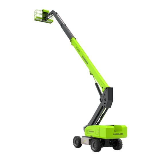
SECTION 7 TECHNICAL PARAMETER Table 7-1 Technical parameter Model ZT26JE Work Height 28.7 m Platform Height 26.7 m Horizontal Outreach 22. 1 m Overall Length (Stowed) 11910 mm Overall Width (Stowed) 2490 mm Size Overall Height (Stowed) 2820 mm Platform Length... - Page 90 Unrestricted load Restricted load Figure 7-1 ZT26JE Range of Motion 用户 00757092 用户 00757092...
- Page 91 Figure 7-2 ZT26JE Dimension (stowed) 7- 3 用户 00757092 用户 00757092...
- Page 93 Add:Tengfei Road 997 , Wangcheng District, Changsha, Hunan,PRC Tel:400-800-0157 E-mail:awm@zoomlion.com Open up the WeChat, Scan the QR code above; All rights reserved 2015 © Zoomlion,reserves all rights,Without the written permission of Zoomlion, the contents of any part of this sample may not be copied for any purpose.
Need help?
Do you have a question about the ZT26JE and is the answer not in the manual?
Questions and answers