Table of Contents
Advertisement
Quick Links
ZOOMLION INTELLIGENT ACCESS MACHINERY CO.,LTD.
Add:Tengfei Road 997, Wangcheng District, Changsha, Hunan,PRC
E-mail:awm@zoomlion.com
Open up the WeChat, Scan the QR code above; All rights reserved 2015 © Zoomlion,reserves all rights,Without the written permission of Zoomlion, the contents of any part of this sample may not be copied for any purpose.
Zip Code:410200
Tel:400-800-0157
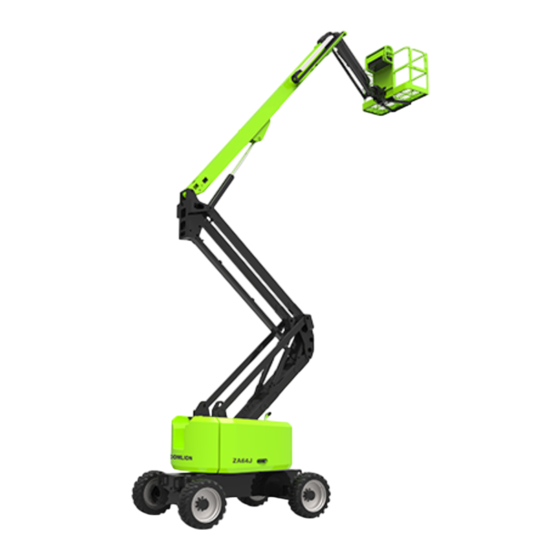
ZA64J
Operation and Safety Manual
NA-OP
Advertisement
Table of Contents

Related Manuals for Zoomlion ZA64J


Summary of Contents for Zoomlion ZA64J
- Page 1 Add:Tengfei Road 997, Wangcheng District, Changsha, Hunan,PRC E-mail:awm@zoomlion.com Tel:400-800-0157 Open up the WeChat, Scan the QR code above; All rights reserved 2015 © Zoomlion,reserves all rights,Without the written permission of Zoomlion, the contents of any part of this sample may not be copied for any purpose.
- Page 3 Operation and Safety Manual ZA64J Operation and Safety Manual 2023.6 A...
- Page 5 This manual has the following safety precaution icons: Failure to comply with the safety precautions listed in this manual could result in personal injury or death. Failure to comply with the safety precautions listed in this manual could result in potential personal injury or death. Failure to comply with the safety precautions listed in this manual could result in potential mild personal injury.
- Page 6 ZOOMLION appreciates your choice of our machine for your application. The Operation and Safety Manual must be read and understood in its entirety before operating the machine. This manual introduces you safety information, significant technical specs, safety operation in detail for working efficiency improving.
-
Page 7: Table Of Contents
Contents Foreword ............................. I Safety Precaution Icons ........................II Contents ............................III SECTION 1 SAFETY PRECAUTIONS ..................1-1 1.1 General ............................1-1 1.2 Pre-operation ..........................1-1 1.3 Hazard Classification ........................ 1-2 1.4 Intended Use ..........................1-2 1.5 Safety Alert Symbols and Maintenance ..................1-2 1.6 Safety Operation ........................ -
Page 8: Contents
Contents SECTION 4 OPERATION INSTRUCTION ................4-1 4.1 General ............................4-1 4.2 Machine Operation ........................4-1 4.2.1 Engine operation ..................... 4-1 4.2.2 Drive operation ......................4-3 4.2.3 Platform leveling ..................... 4-4 4.2.4 Platform rotating ..................... 4-4 4.2.5 Turntable slewing ....................4-5 4.2.6 Raise and lowering the upper boom ................ - Page 9 Contents 5.4.2 Hydraulic Return Filter ..................5-10 5.4.3 Travelling Reduction Gears ................... 5-11 5.4.4 Engine oil、Engine oil filter ................. 5-12 5.4.5 Fuel filter ....................... 5-13 5.4.6 Air filter ......................... 5-14 5.4.7 Engine coolant ....................... 5-14 5.4.8 DPF (Diesel Particulate Filter, for Euro Stage V machine only) ......5-15 5.5 Engine cold start ........................
-
Page 13: Section 1 Safety Precautions
1.1 General To Owners/Users/Operators: Zoomlion appreciates your choice of our machine for your application. Our number one priority is user safety, which is best achieved by our joint efforts. The following requirements need to be adhere to for the purpose of safety operating: Obey all user rules, job site regulations and governmental regulations;... -
Page 14: Hazard Classification
1.3 Hazard Classification Decals on this machine use symbols, color coding, and signal words to identify the following: Safety alert symbol—used to alert you to potential personal injury hazards. Obey all safety messages that follow this symbol to avoid possible injury or death. Indicates a hazardous situation which, if not avoided, will result in death or serious injury. - Page 15 Read operational Read service manual Fire hazard No smoking Explosion hazard manual Maintain required Electrocution hazard Burn hazard Prohibit Step on Avoid contact clearance Electrocution hazard Tip-over hazard Tip-over hazard Tip-over hazard Tip-over hazard Wheel load Wind speed Maximum capacity Tie-down point Lanyard anchorage points Crushing hazard...
- Page 16 No smoking. Runaway hazard Fall Hazards Tire disassembly Explosion hazard No flame. Stop engine. Trained and authorized Stop engine. Prohibit Lifting Lifting point Avoid contact personnel operate the machine only Recovery procedure if tilt alarm sounds while elevated Platform uphill: Platform downhill: 1.
-
Page 17: Safety Operation
1.6 Safety Operation 1.6.1 Operator safety Personal Fall Protection Personal fall protection equipment (PFPE) is required when operating this machine. If PFPE is required in job site or in operator's manual, the following rule should be complied with: all PFPE must comply with applicable governmental regulations, and must be inspected and used in accordance with the PFPE manufacturer’s instructions. - Page 18 Allow for platform movement, electrical line sway or sag, and beware of strong or gusty winds; Keep away from the machine if it contacts energized power lines. Personnel on the ground or in the platform must not touch or operate the machine until energized power lines are shut off. Do not operate the machine during lightning or storms.
- Page 19 Do not depend on the tilt alarm as a level indicator. The tilt alarm sounds in the platform only when the machine is on a severe slope. If the tilt alarm sounds when the platform is raised, use extreme caution. Identify the condition of the boom on the slope as shown below.
- Page 20 Table 1-3 Beaufort scale Beaufort scale Wind speed Instruction 0 0-0.2 m/s 0-0.45mph Calm 0.3-1.5 m/s 0.67-3.36mph Light air 1.6-3.3 m/s 3.58-7.38mph Light breeze 3.4-5.4 m/s 7.61-12.08mph Gentle breeze 5.5-7.9 m/s 12.30-17.67mph Moderate breeze 8.0-10.7 m/s 17.90-23.94mph Fresh breeze 10.8-13.8 m/s 24.16-30.87mph Strong breeze 13.9-17.1 m/s...
- Page 21 Use extreme care and slow speeds while driving the machine in the stowed position across uneven terrain, debris, unstable or slippery surfaces and near holes and drop-offs; Do not drive the machine on or near uneven terrain, unstable surfaces or other hazardous conditions with the boom raised or extended;...
- Page 22 Tip-over hazard Manual force cannot be greater than specification when operating, otherwise may cause tipping over. Table 1-4 Maximum allowable manual force Model Manual force Maximum occupants ZA20J 400 N/90 lbs forse Do not place or attach fixed or overhanging loads to any part of this machine; Do not place ladders or scaffolds in the platform or against any part of this machine;...
- Page 23 Fall Hazards Occupants must wear a safety belt or harness in accordance with governmental regulations. Attach the lanyard to the anchor provided in the platform; Do not sit, stand or climb on the platform guard rails. Maintain a firm footing on the platform floor at all times;...
- Page 24 Collision Hazard Be aware of limited sight distance and blind spots when driving and operating; Check the work area for overhead obstructions or other possible hazards; Be aware of crushing hazards when grasping the platform guard rail; Be aware of the boom position and tail swing when rotating the turntable; Operators must comply with employer, job site, and governmental rules regarding use of personal protective equipment.
- Page 25 Do not lower the boom unless the area below is clear of personnel and obstructions. Limit travel speed according to the condition of the ground surface, congestion, slope, location of personnel, and any other factors which may cause collision. Observe and use the color-coded direction arrows on the platform controls and drive chassis for drive and steer functions.
- Page 26 Immediately tag and remove from service a damaged or malfunctioning machine; Be sure all maintenance has been performed as specified in this manual and the appropriate Zoomlion service manual; Be sure all decals are in place and legible; Be sure operator's, safety, and responsibilities manuals are complete, legible, and in the storage container located on the machine.
- Page 27 Battery Safety Burn hazard Batteries contain acid. Always wear protective clothing and eye wear when working with batteries; Avoid spilling or contacting battery acid. Neutralize battery acid spills with baking soda and water; Do not expose the battery or charger in water or rain while charging. Explosion Hazard Keep sparks, flames, and lighted tobacco away from batteries.
-
Page 31: Section 2 Machine Components And Controls
SECTION 2 MACHINE COMPONENTS AND CONTROLS 2.1 Machine Components Figure 2-1 Components Table 2-1 Component instruction Name Name Foot switch Platform console Manual storage container Main boom (upper boom) Sliding mid-rail Tower boom Lanyard anchorage points Ground control console Swing gate Steering tire Non-steering tire Work platform... -
Page 32: Machine Controls And Indicators
2.2 Machine Controls and Indicators The manufacturer has no direct control over machine application and operation. The user and operator are responsible for conforming with good safety practices. 2.2.1 Ground control console 1.Boom lift, Boom extend/retract, Tower boom lift, Turntable swing, Jib lift, platform leveling, platform rotating device and auxiliary control device both equip with spring so that they will back to neutral when releasing;... - Page 33 Table 2-2 Ground Control Panel Instruction Name Turntable slew switch Main boom lift switch Tower boom lift switch Main boom telescope switch Jib lift switch Platform rotate switch Platform leveling switch Power/Emergency stop switch Platform/Ground Select Switch Engine Start/ Auxiliary Power/Function Enable Switch Display Turntable slew switch Provide 360°...
- Page 34 Jib lift switch (if equipped) Provide raising and lowering of the jib. Platform rotate switch Provides platform rotate controls. Only the platform leveling override function for slight leveling of the platform when platform is lowered. Incorrect use could cause the load/occupants to shift or fall. Failure to do so could result in death or serious injury.
-
Page 35: Ground Control Indicator Panel
Do not enable any of the above motion functions at the same time when operating auxiliary power. (Operate several movement at the same time will cause auxiliary pump motor overloaded.) 10) Engine/ Auxiliary Power/Function Enable Switch Hold the switch in the UP position to start the engine. Turn off the engine and toggle the switch to DOWN position to active auxiliary pump. - Page 36 The function classification is as shown below: Figure 2-4 No.1 indicates title; No.2 indicates fault code; No.3 indicates dynamic parameter monitor; No.4 indicates status indicator, stowed position and work station; No.5 indicates the navigation bar. When the articulating boom lift is in stowed position with no fault code, the interface is as shown below: Figure 2-5...
- Page 37 When the articulating boom lift is in working position with no fault code, the interface is as shown below: Figure 2-6 If the articulating boom lift is in stowed position without system failure alarm, but the engine failure occurs, the interface is as shown below, and the engine failure icon flashes in real time. Figure 2-7 In such case, press the engine failure button to enter the engine failure page, and check the engine fault code in real time, which is convenient for troubleshooting.
- Page 38 Figure 2-8 Click the main interface back to the page shown in Figure 2-7. when the system alarms, the fault code will scroll in the display bar to show the fault code and failure description, see the detail in below: Figure 2-9 22051 indicates fault code and DTC_GENERATOR_FAULT indicates fault description.
- Page 39 Figure 2-10 Figure 2-10 When certain states occur, the status indicator lights up and flashes; when the specific state is released, the turntable indicator light return to gray, as shown in the following figure: Figure 2-11...
- Page 40 Main interface in the second generation display is as follows: Figure 2-12 The function division is shown in the figure below. Figure 2-13 No.1 Indicator display column; No.2 Dynamic parameters monitoring column; No.3 Navigation bar. 1) When some specific status occurs, the status indicator lights up; when the specific status is released, the turntable indicator disappears;...
- Page 41 When the engine fails, the "engine" indicator will start to flash. In this case, press the engine button to enter the engine page, and you can view the engine's fault code in real time, which is convenient for troubleshooting. Its display interface is shown in the figure below. After the engine fault is eliminated, the engine fault indicator stops flashing.
-
Page 42: Platform Control Console
2.2.3 Platform control console Avoid serious injury, do not operate machine if any control levers or toggle switches controlling platform movement do not return to the off or neutral position when released. Figure 2-12 Platform control panel (Only the switch number corresponding to the existing function is identified.) Table 2-3 Platform control panel instruction Name... - Page 43 Avoid serious injury, do not operate machine if any control levers or toggle switches controlling platform movement do not return to the off or neutral position when released. Drive select switch Provides high speed, and low speed. The forward position gives maximum drive speed; The downward position gives maximum drive torque for rugged terrain or climbing condition;...
- Page 44 Move the drive controls in a direction matching the directional arrows. Drive/Steer controller Provides drive/steer controls. Push forward to drive forward, pull back to drive in reverse. Steering is accomplished via a thumb-activated rocker switch on the end of the steer handle.
-
Page 45: Platform Control Indicator Panel
Tower boom lift switch Provides for raising and lowering of tower boom when positioned up or down. 2.2.4 Platform control indicator panel Note:The indicator lights will illuminate for approximately 1 second when the key is positioned to the on position to act as a self test. Figure 2-13 Platform Control Indicator Panel Table 2-4 Platform Indicator Panel Instruction Name... - Page 46 If leveling system fault indicator lights up, shut off the machine and restart. If fault occurs again, retract the platform to stowed position via manual level function, and service the leveling system. Platform overload indicator. Indicates the platform has been overloaded. Wire rope loosen indicator (not equipped).
- Page 47 Creep speed indicator. When the Function Speed Control is turned to the creep position, the indicator acts as a reminder that all functions are set to slowest speed. The light will be on continuously if the operator selects creep speed. Foot switch indicator.
-
Page 48: Safety Device
12) Low fuel indicator. Indicates a low fuel condition in the tank. 13) Limited position indicator. Indicates limited position of boom. 14) Limited position indicator. Indicates limited position of boom. 2.2.5 Safety device The anti-crushing device is installed on the armrest at the platform console to avoid unobserved crushing injuries encountered during the operation of the equipment. -
Page 51: Section 3 Machine Inspection
Section 3 MACHINE INSPECTION 3.1 General An operator must not operate the machine, only if: He has learned and practiced the principles of safe machine operation contained in this operational manual. Only use the machine as it was intended; Know and understand the pre-operation inspection before going on to the next section; Implement functional test before operating the machine at all times;... - Page 52 Check for engine oil leak and proper fluid level. Add oil if needed. See Maintenance section; Check for engine coolant leak and proper level of coolant. Add coolant if needed. See Maintenance section; Check the following components or areas for damage, improperly installed, or missing parts and unauthorized modifications: Electrical components, wiring, and electrical cables;...
-
Page 53: Ground Function Check
3.2 Function Test 3.2.1 Function test principle The function tests are designed to discover any malfunctions before the machine is put into service. The operator must follow the step-by-step instructions to test all machine functions; A malfunctioning machine must never be used. If malfunctions are discovered, the machine must be tagged and removed from service. -
Page 54: Platform Function Check
Attempt to activate each boom and platform function button. Check test result: All boom and platform functions should operate through a full cycle. Test auxiliary power Start the engine at the ground controls; Pull the red Power/Emergency Stop Switch button to on position; Operate Auxiliary Power Switch;... - Page 55 Attempt to activate each boom and platform function button. Result: all boom and platform functions except driving and steering should operate at the auxiliary power mode. Test the Horn Press the horn button at the platform controls. Check test result: The horn should sound. Test the Steering Select Platform Mode;...
-
Page 56: Workplace Inspection
Lower the upper boom to stowed position; Extend the upper boom 0.5m; Attempt to operate drive handle; Check test result: the drive speed should switch to low speed with the upper boom extended. Lower the upper boom to stowed position; Attempt to operate drive handle. -
Page 57: Decal Inspection
bumps, floor obstructions, or debris; Sloped surfaces; Unstable or slippery surfaces; Overhead obstructions and high voltage conductors; Hazardous locations; Inadequate surface support to withstand all load forces imposed by the machine; Wind and weather conditions; The presence of unauthorized personnel; Other possible unsafe condition. - Page 58 Figure 3-1 Decal position (continuous)
- Page 59 Figure 3-1 Decal position (continuous)
- Page 60 Figure 3-1 Decal position (continuous) 3-10...
- Page 61 Figure 3-1 Decal position (continuous) Use the pictures on next page to verify that all decals are legible and in place. Below is a numerical list with quantities and descriptions. 3-11...
- Page 62 Table 3-1 Decal Numbers are corresponded to the decal (not all decal are pasted on the machine) Part. No/Description Decal 00771407000201100 Label- Yellow triangle 00771407000201080 Label- Blue arrow 00771407000201110 Label- Blue triangle 00771407000201090 Label- Yellow arrow 00773407000401271 Warn- Prohibit high pressure water-bleakest 02564707021601050 Hazard- Tip-over Hazard...
- Page 63 Table 3-1 Decal (continuous) Numbers are corresponded to the decal (not all decal are pasted on the machine) Part. No/Description Decal 00773407000401321 Warn- Crushing hazard II 00773407000401201 Caution- Prohibit Lanyard 00773407000401231 Warn- Foot Switch Malfunction 00773407000401141 Label- Platform Console Instruction 00773407010401021 Label-Handrail position 00773407010401021...
- Page 64 Table 3-1 Decal (continuous) Numbers are corresponded to the decal (not all decal are pasted on the machine) Part. No/Description Decal 00773407000401221 Label- Platform Indicator Panel Instruction 02564707021601330 Label- Work Platform 02564707021601530 Label-Hood 00773407000401511 Caution-Cold starting 00773407000401251 Label-Plug stop pin when transporting 00773407000401391 Caution-Preserve the manual...
- Page 65 Numbers are corresponded to the decal (not all decal are pasted on the machine) Part. No/Description Decal 00773407000201181 Label- Prohibit Step on 00773707000201101 Label- Minimum fuel level 00773707000201111 Label- Maximum fuel level 00773407000401381 Danger- Explosion Hazard II 00773407000401151 Caution- Cut off Battery 00773407000201010 Label-Zoomlion LOGO I 00773407000201421 Label- Tie down point 3-15...
- Page 66 Table 3-1 Decal (continuous) Numbers are corresponded to the decal (not all decal are pasted on the machine) Part. No/Description Decal 00773407000201241 Label- Prohibit Lifting 00773707021601020 Model LOGO I 00773707000401371 Nameplate 00773407000401191 Danger- Crushing Hazard 00773407000401311 Danger- Tip-over Hazard II 00773407000201431 Label- Lift point 00775607000401321...
- Page 67 Table 3-1 Decal (continuous) Numbers are corresponded to the decal (not all decal are pasted on the machine) Part. No/Description Decal 00773407000401211 Danger- Crushing Hazard 00773407000401471 Hazard-Burn 00773407010401441 Caution- Main Power Operating Instruction 00773707031601051 Label- Wheel Load 00773407000401561 Danger- Tip-over Hazard III 00773407000201061 Follow instructions to refuel 02564707021601060...
- Page 68 Table 3-1 Decal (continuous) Numbers are corresponded to the decal (not all decal are pasted on the machine) Part. No/Description Decal 00773407000401081 Label- Platform Indicator Panel Instruction 00773407000401461 Label-Platform AC power 00773407000401171 Hazard-Prohibit contact 00773407000201030 Label-Zoomlion LOGO III 00773707021601030 Label- Model LOGO-II 3-18...
- Page 69 Table 3-1 Decal (continuous) Numbers are corresponded to the decal (not all decal are pasted on the machine) Part. No/Description Decal 00771107000201250 Label-Noise 00771407000401191 QR code 3-19...
-
Page 73: Section 4 Operation Instruction
SECTION 4 OPERATION INSTRUCTION 4.1 General An operator must not operate the machine, only if: He has learned and practiced the principles of safe machine operation contained in this operational manual. Avoid hazardous situations; Perform a pre-operation inspection at all times; Implement functional test before operating the machine at all times;... - Page 74 DO NOT operate machine; If an engine malfunction causes a unscheduled shutdown, determine the cause and correct it before restarting the engine; Consult ZOOMLION customer service to know more about the operation under abnormal conditions. 4.2.1.1 Engine start Machine with diesel engines.
-
Page 75: Drive Operation
4.2.1.2 Engine shut down sequence Remove all load and allow engine to operate at low speed for 3-5 minutes. This allows further reduction of internal engine temperature; Push in Power/Emergency Stop switch; Turn the Platform/Ground select switch to Off position. Refer to Engine Manufacture’s manual for detailed information. -
Page 76: Platform Leveling
4.2.2.1Traveling forward and reverse At Platform Controls, pull out Emergency Stop switch, start the engine, and activate foot switch; Position DRIVE/STEER control to “FORWARD” OR “REVERSE” hold for duration of forward or reverse travel desired. This machine is equipped with travelling direction indicator lights. The indicator lights on platform console to inform that upper boom is over front axle (steer wheels), steer and drive controls will move in opposite direction than indicated on machine placards. -
Page 77: Turntable Slewing
4.2.4 Platform rotation To rotate the platform to the left or right, use the Platform Rotate control switch to select the direction and hold until desired position is reached. Do not swing or raise upper boom above horizontal position when machine is out of level. Do not use the tilt alarm as a level indicator for the chassis. -
Page 78: Raising And Lowering The Jib
4.2.9 Raising and lowering the jib To raise or lower the Jib, position the Jib Lift to Up or Down until the desired height is reached. 4.2.10 Emergency stop Push in the red “Emergency Stop” button on Ground or Platform Controls to off position to shut off all the functions. -
Page 79: Transport And Lifting
The transport vehicle must be secured to prevent rolling while the machine is being loaded. Be sure the vehicle capacity, loading surfaces and chains or straps are sufficient to withstand the machine weight. ZOOMLION lifts are very heavy relative to their size. See the serial label for the machine weight. -
Page 80: Lifting
be towed, the speed must not exceed 3.2 km/h. Securing to Truck or Trailer for Transit Always use the turntable rotation lock pin each time the machine is transported. Panel Cradle Installation Insert the hook piece through the slots in the panel cradle base. Inspect the entire machine for loose or unsecured items. - Page 81 Figure 4-2 Securing the Platform Use a cable tie or rope to secure the slider to the upper square tube of the work platform to prevent the slider from bumping during transportation. Figure 4-3 Securing the Platform...
-
Page 85: Section 5 Maintenance
Disposal of materials should be according to the regulations of government and relevant environmental protection administration; Use only ZOOMLION approved replacement parts. ZOOMLION assumes no responsibility for hazards occurred to equipment and personnel caused by the use of unauthorized parts. -
Page 86: Maintenance Hazards
Drive motor/motor; Wear pads; Tires and wheels; Limit switches and horn; Alarm and indicator (if equipped); Nuts, bolts and other fasteners; Brake release unit. 5.1.3 Maintenance hazards Shut off power to all controls and ensure that all moving parts are secured from inadvertent motion prior to performing any adjustments or repairs;... -
Page 87: Power And Hydraulic System Maintenance
5.2 Power and Hydraulic System Maintenance 5.2.1 Check the engine oil level Maintain the engine coolant at the proper level is essential to engine service life. Improper coolant level will affect the engine’s cooling capacity and damage engine components. Check the engine oil gauge everyday, make sure the oil level is between the highest and lowest scales. Select different engine oil according to different working temperatures and engine configurations (see Table 5-1). -
Page 88: Check The Engine Coolant Level
Table 5-2 Fuel Requirement Environmental Temperature Type (-44 ~ -29)℃ -50# (-29 ~ -14)℃ -35# (-14 ~ -5)℃ -20# (-5 ~ 4)℃ -10# (4 ~ 8)℃ 8℃以上 5.2.3 Check the engine coolant level Check the engine oil gauge everyday, make sure the oil level is between the highest and lowest scales. Select different engine oil according to different working temperatures and engine configurations (see Table 5-1). -
Page 89: Check Hydraulic Oil
Note: DO NOT mix oils of different brands or types, as they contain different additives which may cause negative effects. If mixing of hydraulic oils is unavoidable, permission must be obtained from the hydraulic oil manufacturer. After-sales service of ZOOMLION does not cover machine malfunction caused by hydraulic oil mixing. - Page 90 Table 5-2 Technical parameters of hydraulic oil Great Wall Mobil Kunlun 10 4632 grease MobilD MobilD MobilD Great Great Calte Calte aviation non-flammab Technical Aware TE 10 TE 10 TE 10 Wall Wall Rando Rando hydraulic le hydraulic Parameter H 32 Ultra Ultra Ultra...
-
Page 91: Battery Maintenance
machine components and work efficiency, it is advisable that the starting temperature should be 25℃ /77℉ higher than the pour point of hydraulic oil. Changing hydraulic oil We suggest that changing time of the hydraulic oil is as follows: First changing:operating for 500 hrs after commissioning; Second and subsequent changing:every 2,000 hrs of operation or once a year. -
Page 92: Regular Maintenance
Electrocution hazard Contact with hot or live circuits may result in death or serious injury. Remove all rings, watches and jewelry. Body injury hazard Batteries contain acid.Avoid spilling or contacting battery acid. Neutralize battery acid spills with baking soda and water. Note: the battery should be fully charged before this inspection. -
Page 93: Rotation Reduction Gears
5.4.1 Rotation reduction gears Lube Point(s) –Replaceable Filter. Capacity –As required. Lube -Changcheng 7408B-1 Gear Grease. Interval –Every 4 months or 150 hours. Comment –Apply grease and rotate in 90 degree intervals until bearing is completely lubricated. DO NOT over-lubricate the bearings, otherwise it will cause damage to outside seal of casing. 5.4.2 tank Hydraulic... -
Page 94: Hydraulic Return Filter
5.4.2 Hydraulic return filter Maintenance Point(s) –Replaceable Element. Interval –Change after first 50 hrs. and every 6 months or 1,000 hrs. Hydraulic tank breather Maintenance Point(s) –Tank Breather Interval –Change after first 50 hrs. and every 6 months or 1,000 hrs thereafter. Comment –Remove wing nut and cover to replace.Under certain conditions, it may be necessary to replace on a more frequent basis. -
Page 95: Travelling Reduction Gears
5.4.3 Travelling reduction gears Lube Point(s) –Level/Fill Plug. Capacity –1 L (0.3 us gal). Model:SAE80W/90 Industrial Gear Oil for Close Motor. Interval – Check level every 3 months or 150 hours of operation;change every year or 2,000 hours of operation. Lube Point(s) –Fill Plug. -
Page 96: Engine Oil、Engine Oil Filter
5.4.4 Engine oil、Engine oil filter KUBOTA V2403-M-DI-ET04 WEICHAI WP3.2G50E317A KUBOTA V2403 -CR-EW02 WEICHAI WP3.2G50E433 Maintenance point- Replace engine oil Capacity- KUBOTA V2403-M-DI-ET04/ KUBOTA V2403 -CR-EW02 around 9.5L、 WEICHAI WP3.2 G50E317A/ WEICHAI WP3.2G50E433 around 9.5L。 Interval- First maintenance after 50 hours of use, thenafter, every 6 months or 500 hours of operation, whichever comes first. -
Page 97: Fuel Filter
5.4.5 Fuel filter a) First class fuel filter KUBOTA V2403-M-DI-ET04 WEICHAI WP3.2G50E317A KUBOTA V2403 -CR-EW02 WEICHAI WP3.2G50E433 Maintenance point- Replaceable element. Interval- Drain off water everyday, every 6 months or 500 hrs of operation, whichever comes first. Comment –Change in accordance with engine manual. b)... -
Page 98: Air Filter
5.4.6 Air filter Maintenance Point(s) –Replaceable Element. Interval –Every 6 months or 500 hours of operation or as indicated by the condition indicator. Note: check dustproof valve everyday. Change in accordance with engine manual. (1)Air filter main body(2)Lid (3)Safety filter (4)Main filter element (5)Dust valve After using for no more than 500 hours, the main filter element can be purged with compressed air, but the pressure must be lower than 205kPa, and the number of purges should not exceed 6 times. -
Page 99: Dpf (Diesel Particulate Filter, For Euro Stage V Machine Only)
Maintenance Point(s) –Add/replace anti-freezing solution. Refilling requirements: After running the engine for 5 minutes, the coolant level in the cooling water tank is between the MIN and MAX scale lines. Battery Level: KUBOTA V2403-M-DI-ET04/ KUBOTA V2403 -CR-EW02 around 11L;WEICHAI WP3.2G50E317A/ WEICHAI WP3.2G50E433 around 12L。 Interval –Check oil level daily, change every 2000 hours or one year (whichever come first). -
Page 100: Engine Cold Start
Regeneration prohibitedswitch Regeneration switch KUBOTA V2403 -CR-EW02 Maintenance point: DPFregeneration. Interval: Whenever the regeneration request light is on. Operation method: park the machine in a place without fire risk, after starting the engine, turn the regeneration switch upward, the engine will automatically enter the regeneration process, and it will take about 40 minutes to complete the regeneration. -
Page 101: Fuel System Exhaust
Glow plug indicator b)The engine should run at idle speed for 10min before other operation. Note: Do not start the engine frequently to avoid irreversible damage to the engine. Note: When the ambient temperature is lower than -20° C, additional auxiliary starting equipment (such as electric heater) is required to start. -
Page 102: Engine
ZOOMLION recommends a replacement tire be the same size, ply and brand as originally installed on the machine. Please refer to the ZOOMLION Parts Manual for the part number of the approved tires for a particular machine model. If not using a ZOOMLION approved replacement tire, we recommend that replacement tires have the following characteristics: Equal or greater ply/load rating and size of original;... - Page 103 Wheel nuts must be installed and maintained at the proper torque to prevent loose wheels, broken studs, and possible dangerous separation of wheel from the axle. Be sure to use only the nuts matched to the cone angle of the wheel. Tighten the lug nuts to the proper torque to prevent wheels from coming loose.
-
Page 107: Section 6 Storage And Ex-Factory Test
SECTION 6 STORAGE AND EX-FACTORY TEST 6.1 Storage Conditions Ambient temperature for machine storage and transportation should be between -20℃/-4℉ and 40℃/104℉, with relative humidity not greater than 85% and 100% only for short-term. 6.2 Ex-factory Test Items Machine must complete testing items in the following table before delivery: Table 6-1 Testing Items Before Delivery Tests Items Load Testing... -
Page 111: Section 7 Technical Parameter
SECTION 7 TECHNICAL PARAMETER Table 7-1 Technical Parameters Model ZA64J Parameters 63ft 7in Platform Height 19.38m 40ft 4in Max Horizontal Outreach 12.30m 27ft 1in Up and Over Height 8.25m 28ft 11in Overall Length 8.82m 8ft 1in Dimension Overall Width 2.46m... - Page 112 Table 7-1 Technical Parameters (Continuous) Model ZA64J Parameters Platform Rotation ± 90° Jib Working Range -60° ~70° Upper Boom Working Range -42° ~70° Range of Motion 12ft 6in. Upper Boom Retract 3800mm Tower Boom Working Range 0° ~72° Turntable Swing 360°...
- Page 113 Figure 7-1 ZA64J Range of Motion...
- Page 114 Figure 7-2 ZA64J Dimension in Traveling Mode...
Need help?
Do you have a question about the ZA64J and is the answer not in the manual?
Questions and answers