Table of Contents
Advertisement
Quick Links
Zoomlion Heavy Industry Science & Technology Co.,Ltd.
Address: Quantang Industrial Park, No. 1636, 2nd Yuanda Road, Changsha, Hunan Province, China
Website: http:/ /www.zoomlion.com
Email: Sos-service@zoomlion.com
Copyright © 2015 Zoomlion Heavy Industry Science&Technology Co., Ltd. All rights reserved
Postcode: 410131
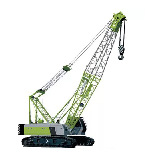
CRAWLER CRANE
OPERATOR'S MANUAL
Advertisement
Table of Contents

Related Manuals for Zoomlion ZCC2600CR


Summary of Contents for Zoomlion ZCC2600CR
- Page 1 OPERATOR’S MANUAL Zoomlion Heavy Industry Science & Technology Co.,Ltd. Address: Quantang Industrial Park, No. 1636, 2nd Yuanda Road, Changsha, Hunan Province, China Postcode: 410131 Website: http:/ /www.zoomlion.com Email: Sos-service@zoomlion.com Copyright © 2015 Zoomlion Heavy Industry Science&Technology Co., Ltd. All rights reserved...
- Page 3 ZCC2600CR Crawler Crane Operator’s Manual Edition 1 July 2018...
-
Page 5: To Users
Under the copyright laws, this manual may not be copied, photocopied, reproduced, translated, or reduced to any electronic medium or machine readable form, in whole or part, without the prior written consent of Zoomlion Heavy Industry Science and Technology Co., Ltd. -
Page 6: Safety Instructions
Operator’s Manual for Crawler Crane Safety Instructions The following terms that are used in these operating instructions "Danger", "Warning", "Caution" and "Notice" are intended to point out certain important rules of conduct to all persons who work with the crane. The meanings of the terms are as follows: Refers to a dangerous situation which, if you do not prevent, will cause DANGER death or injury. -
Page 7: Table Of Contents
Operator’s Manual for Crawler Crane Contents To Users .............................. I Safety Instructions ..........................II Chapter 1 Safety 1.1 Important instructions ....................... 1-1 1.1.1 Notes ........................1-1 1.1.2 Alarms and warnings .................... 1-1 1.2 Component safety features ....................1-2 1.3 Features for operator safety ..................... 1-2 1.4 Environmental safety ...................... - Page 8 Operator’s Manual for Crawler Crane 2.3.3 Slewing mechanism ....................2-7 2.3.4 Travel gear ......................2-7 2.3.5 A-frame erecting mechanism ................2-8 2.3.6 Operator’s cab movement-controlling mechanism ..........2-8 2.3.7 Counterweight and its fitting & removal mechanism ..........2-8 2.3.8 References ......................2-8 2.3.9 Classification of the crane ..................
- Page 9 Operator’s Manual for Crawler Crane 3.2.14 Establishing the prohibited zone ..............3-23 3.2.15 Electromagnetic influences ................3-24 3.2.16 Endangering the environment ................3-25 3.3 Rigging ........................... 3-26 3.3.1 Rigging introduction .................... 3-26 3.3.2 Rigging hardware ....................3-26 3.3.3 Hooks ......................... 3-26 3.4 Slings ..........................
- Page 10 Operator’s Manual for Crawler Crane Chapter 4 Crane Operation 4.1 Operating and control instruments ................... 4-1 4.1.1 Operator’s cab, overview ..................4-1 4.1.2 Left control box ..................... 4-3 4.1.3 Right control box ....................4-4 4.1.4 Control panel assy....................4-6 4.1.5 Right control panel ....................
- Page 11 Operator’s Manual for Crawler Crane 4.6.2 Light duty boom (SL) ..................4-91 4.6.3 Fixed jib on heavy duty boom (SF) ..............4-92 4.6.4 Luffing jib on heavy duty boom (SW) ..............4-93 4.6.5 Derricking rope guidance and reeving ............... 4-94 4.6.6 Luffing rope guidance and reeving ..............
- Page 12 Operator’s Manual for Crawler Crane 5.9.2 Assembling main boom with luffing jib..............5-112 5.9.3 Connect electrics to luffing jib................5-126 5.9.4 Erecting and lowering main boom with luffing jib..........5-134 5.10 Assembly and dismantling of light duty boom (SL)............5-142 5.11 Assembly and dismantling of main boom with fixed jib (SF).........5-144 5.11.1 Preparations.....................5-144 5.11.2 Assembling main boom with fixe jib..............5-144 5.11.3 Connect electrics to fixed jib................5-153...
-
Page 13: Chapter 1 Safety
Operator’s Manual for Crawler Crane Chapter 1 Safety... -
Page 15: Important Instructions
Operator’s Manual for Crawler Crane Chapter 1 Safety 1.1 Important instructions 起 重 1.1.1 Notes 机 说 Read this manual and familiarize yourself with any associated documents before operating 明 this crane. Ensure that a copy of this manual is available to any person installing, using, maintaining or repairing this crane. -
Page 16: Component Safety Features
Operator’s Manual for Crawler Crane 1.2 Component safety features Do not use this crane with guards removed or incorrectly fastened. Do not use this crane with safety devices maladjusted or removed. 1.3 Features for operator safety Safety component – crane emergency stop button. Ensure all safety components are in place. -
Page 17: Measured Noise Level
Operator’s Manual for Crawler Crane 2) Safety glasses/Goggles 3) Hearing protection device 4) Close fitting overalls 起 重 5) Safety boots 机 6) Industrial gloves 说 7) High visibility vest or jacket 明 1.6 Measured noise level The condition of working site may affect the noise levels. According to EN13000 Annex G and 2000/14/ EC standards, the sound pressure level and sound power level measured in the operator’s cab are 73.9 dB(A) and 107 dB(A) respectively. -
Page 18: Personnel Qualification, Requirements And Responsibilities
Operator’s Manual for Crawler Crane 1.9 Personnel qualification, requirements and responsibilities Any work on and / or with the crane must be executed by trained, reliable and authorized personnel only. The maintenance work must only be undertaken by suitable qualified engineers with specialist knowledge of this crane. -
Page 19: Gas, Dust, Steam, Smoke And Noise
Operator’s Manual for Crawler Crane system. 2) Recharge the battery in a well ventilated area. 3) The battery contains sulphuric acid, an electrolyte which can cause severe burns and 起 重 produce explosive gases. Therefore, avoid contact with the skin, eyes or clothing. 机... -
Page 21: Chapter 2 Description Of Crane
Operator’s Manual for Crawler Crane Chapter 2 Description of Crane... -
Page 23: Product Model
生产地址:中国湖南长沙岳麓区银盆南路361号 Address.:No.361.Yin Pen Road.Changsha Hunan.P.R.China 中 联 重 科 股 份 有 限 公 司 制 造 MANUFACTURER: ZOOMLION HEAVY INDUSTRY SCIENCE & TECHNOLOGY CO LTD. Figure 2-1 Product name plate and its position 2.1.2 Intended use of the crane... -
Page 24: Crane Design Calculation
Operator’s Manual for Crawler Crane The use of two hoisting winches for lifting loads (twin hook operation) is only permitted following permission from the crane manufacturer. The intended use also includes the observation of Lifting Load Capacity Chart, Operator’s Manual and Maintenance Manual. 2.1.3 Crane design calculation 2.1.3.1 General The crane has been constructed using state of the art technology and in accordance with... -
Page 25: Engine Type And Its Manufacturer
Operator’s Manual for Crawler Crane The load spectrum coefficient of the crane should comply with the load collective class (lift the rated load rarely, but the medium-duty load frequently). For example: For 1/6 of the load cycles, the crane is placed under the maximum load. 起... -
Page 26: Terminology
Operator’s Manual for Crawler Crane 2.2 Terminology 2.2.1 Boom configurations Figure 2-2 Boom configurations Table 2-1 Description of boom configurations Configuration Description Parameters Heavy duty boom 20m-83m Light duty boom 86m-95m Luffing jib on heavy S-boom =23m-62m duty boom W-jib = 21m-60m Fixed jib on heavy duty S-boom = 29m-77m boom... -
Page 27: Description Of Crane Components
Operator’s Manual for Crawler Crane 2.2.2 Description of crane components 起 重 机 说 明 Figure 2-3 Names of the components... - Page 28 Operator’s Manual for Crawler Crane Figure 2-4 Names of the components Table 2-2 Description of component parts Part No. Description Part No. Description Counterweight Central counterweight Drive sprocket Hoisting winch 1 Crawler carrier Hoisting winch 2 Track roller Slewing reducer Track carrier roller Main boom derricking winch Track pad...
-
Page 29: Product Description
Operator’s Manual for Crawler Crane 2.3 Product description 2.3.1 Hoisting winches 起 重 The crane is fitted with two hoisting winches: hoisting winch 1 and hoisting winch 2. Both of 机 them are composed of concealed axial piston variable displacement motor, balance valve, 说... -
Page 30: A-Frame Erecting Mechanism
Operator’s Manual for Crawler Crane 2.3.5 A-frame erecting mechanism The A-frame erecting mechanism consists of A-frame, erection cylinder, auxiliary hydraulic system and so on. It is mainly used for the assembly, dismantling or conversion of the machine on the site. The erection cylinder is connected to balance valve with anchoring rods. -
Page 31: Crane Working Environment
Operator’s Manual for Crawler Crane 2.3.10 Crane working environment Working temperature: -20 ℃- 40 ℃ 起 Non-working temperature: -40 ℃- -20 ℃, 40 ℃- 60 ℃ 重 机 Allowed air relative humidity: 85% (100% is allowed for a short period of time) 说... -
Page 32: Technical Data
Operator’s Manual for Crawler Crane 2.4 Technical data 2.4.1 Main technical parameter Table 2-3 Weight Basic machine 45.5 t Rear counterweight 83.7 t Central counterweight 32 t Crawler carrier 2 × 24.5 t Table 2-4 Speed Mechanism Speed Rope diameter 120 m/min (maximum speed of single rope, Hoisting winch 1 28 mm... -
Page 33: Hoisting Rope Reeving And Specification Of Wire Rope
Operator’s Manual for Crawler Crane 2.4.3 Hoisting rope reeving and specification of wire rope Table 2-6 Hoisting rope reeving 起 重 Lifting Lifting Lifting Reeving Reeving Reeving 机 Capacity (t) Capacity (t) Capacity (t) 说 明 CAUTION (1) If crane is working with hoisting rope reeving less than the value listed in the above table, single hoisting rope load must be checked to make sure that the max. -
Page 34: Lifting Height
Operator’s Manual for Crawler Crane 2.4.4 Lifting height CAU TION The lifting height curve is drawn without consideration of boom deflection. Lifting height on S/SL boom Unit: m 83° 80° 70° 60° 50° 40° 30° Figure 2-8 Lifting height on S/SL boom CAUTION (1) The X-axis indicates the working radius in meters, and the Y-axis indicates the lifting height in meters. - Page 35 Operator’s Manual for Crawler Crane Lifting height on SF boom Unit: m 80° 10° 起 70° 重 30° 60° 机 说 明 50° 40° Figure 2-9 Lifting height on SF boom CAUTION (1) The X-axis indicates the working radius in meters, and the Y-axis indicates the lifting height in meters.
- Page 36 Operator’s Manual for Crawler Crane Lifting height on SFV boom Unit: m 80° 10° 70° 30° 60° 50° 40° Figure 2-10 Lifting height on SFV boom CAUTION (1) The X-axis indicates the working radius in meters, and the Y-axis indicates the lifting height in meters.
- Page 37 Operator’s Manual for Crawler Crane Lifting height on SW boom 75° Unit: m 起 65° 重 55° 机 说 45° 明 35° 25° 15° 54 60 85° 75° 65° Figure 2-11 Lifting height on SW boom CAUTION (1) The X-axis indicates the working radius in meters, and the Y-axis indicates the lifting height in meters.
-
Page 38: Lifting Capacity Charts
Operator’s Manual for Crawler Crane 2.4.5 Lifting capacity charts The values in lifting capacity charts are applicable to 360° working condition. The value in lifting capacity charts is the rated total lifting capacity of crane, which is the maximum permitted lifting capacity under various boom configurations. It includes the weight of load hook, wire rope and other load handling devices. - Page 39 Operator’s Manual for Crawler Crane Table 2-8 Formula explanation G= Rated lifting capacity L1=Main boom radius 起 G1= Jib weight L2=Jib length 重 机 α= Main boom angle G2= Actual lifting capacity 说 明 β=Jib angle (10° or 30°) G3= Main load hook G4= Auxiliary load hook Figure 2-13 Actual lifting capacity calculation when main boom is with jib The rated total lifting capacity indicates the crane’s lifting capacity under different boom...
- Page 40 Operator’s Manual for Crawler Crane CAUTION For your safety, using both load hooks is prohibited during lifting operation. 2-18...
-
Page 41: Chapter 3 Safety Guidelines
Operator’s Manual for Crawler Crane Chapter 3 Safety Guidelines... -
Page 43: Operational Planning
Operator’s Manual for Crawler Crane Chapter 3 Safety Guidelines 起 3.1 Operational planning 重 机 In addition to a perfectly working crane and a well-trained crew, operational planning is an 说 important precondition for safe and reliable crane operation. 明 The crane operator must obtain or receive the necessary information (familiarize himself with the Operator’s Manual, basic knowledge about pneumatic, electrical and hydraulic drive, and notes for safe operation as well as operating environment) before starting the crane operation,... -
Page 44: State-Of-The-Art Technology
Operator’s Manual for Crawler Crane 3.1.1 State-of-the-Art Technology This crawler crane model represents the latest state-of-the-art technology. Load capacities The proper load capacities are found using the lifting capacity chart. However, the equipment can still pose a hazard or danger if the safety procedures are not observed and implemented. -
Page 45: Areas Of Responsibility
Operator’s Manual for Crawler Crane Dragging the load on the ground Excessive diagonal pull exceeding 2% of the maximum permitted hoisting load. Crane operation without the specified safety devices such as load moment limiter, hoisting 起 重 limiter etc 机 Crane operation without observing proper lifting capacity charts. -
Page 46: Personal Protective Gear
Operator’s Manual for Crawler Crane Report all irregularities that may or may not affect the safe operation of the crane to superior department or user immediately. Stop operation at once if safe operation is no longer possible. Make sure that all control devices are in their neutral positions and the engine is turned off before leaving the operator’s cab. -
Page 47: Work Area
Operator’s Manual for Crawler Crane 起 重 机 说 明 Figure 3-5 Safety boots Figure 3-6 Protective gloves CAUTION Any operator must observe the following: (1) Be equipped with necessary personal protective gear. (2) Keep all personal protective gear clean. (3) Change the damaged protective clothing and gear in time. -
Page 48: Safety Technical Notes
Operator’s Manual for Crawler Crane 3.2 Safety technical notes 3.2.1 Safety instructions for crane operator Safety instructions for crane operator The crane operator’s primary responsibility is to control, operate and adjust the crane in a manner that is safe for both himself and others. Therefore the crane operator should meet the following requirements. - Page 49 Operator’s Manual for Crawler Crane Be trained in the skill of handling load. Be able to choose proper lifting devices and components according to the loading condition. 起 重 Be trained in hand signals for operation and familiar to use them. 机...
-
Page 50: Selecting An Operating Site
Operator’s Manual for Crawler Crane 3.2.2 Selecting an operating site It is very important to choose an appropriate location for crane operation in order to minimize safety risks. The operating site should be selected so that: Crane movement can be carried out within the smallest possible radius. No obstacles hinder necessary movements in the working radius. -
Page 51: Permissible Ground Pressure
Operator’s Manual for Crawler Crane 3.2.4 Permissible ground pressure Table 3-1 Permissible ground pressure 起 Soil type Ground pressure (unit: ×0.1MPa) 重 机 Back-filled, not naturally compacted ground 说 明 Natural soil, apparently undisturbed 1. Mud, peat, marshy land Non-cohesive, sufficiently compactly layered soil Fine to medium grained sand From coarse-grained sand to gravel... -
Page 52: Checking Safety Measures
Strong electromagnetic fields are likely to be present if the construction site is close to a transmitter. In any case, before working with the crane near transmitters, contact Zoomlion representative. In addition, consult a high frequency specialist. Every crane must be “totally” grounded. Check visually or with a simple tester to ensure that the ladder, cab and cable pulleys are grounded. -
Page 53: Safety Signs
Operator’s Manual for Crawler Crane Loads must be grounded, or additional insulation used (rubber material between the tools used and gloves) when manual work is required. To avoid accidents, use a safety belt when working on components that are high off the 起... - Page 54 Operator’s Manual for Crawler Crane Figure 3-44 Note: Lifting point Figure 3-45 Warning: Risk of falling Figure 3-46 Danger: Snagging/dragging Figure 3-47 Danger: Risk of burn Figure 3-48 Prohibited: No access for Figure 3-49 Prohibited: Access prohibited unauthorized personnel Figure 3-50 Warning: Keep off outriggers Figure 3-51 Prohibited: Naked flames 3-12...
- Page 55 Operator’s Manual for Crawler Crane 起 重 机 说 明 Figure 3-52 Note: First aid kit Figure 3-53 Note: Fire extinguisher Figure 3-54 Warning: Do not stand under Figure 3-55 Caution: Be careful in the boom working radius 3-13...
- Page 56 Operator’s Manual for Crawler Crane Figure 3-56 Position of safety sign 3-14...
- Page 57 Operator’s Manual for Crawler Crane 起 重 机 说 明 Figure 3-57 Position of safety sign 3-15...
-
Page 58: Potential Dangers Existing In Crane Operation
Operator’s Manual for Crawler Crane Figure 3-58 Position of safety sign CAUTION (1) When the safety sign is damaged or illegible, please order it from appointed service supplier. (2) It is forbidden to cover or take off safety signs. (3) If the safety sign is covered with dust and dirt, clean it in time. (4) The operator’s cab should be equipped with an emergency hammer which can be used to smash the window in an emergency so that the operator can run away from the cab. - Page 59 Operator’s Manual for Crawler Crane No one is allowed in danger zone of the crane. 起 重 机 说 明 Figure 3-60 Do not reach into moving drives or parts of the crane Figure 3-61 Access to the top of the upper carriage is only permitted: –...
-
Page 60: Injuries Due To Hydraulic Energy
Operator’s Manual for Crawler Crane WARNING Dangers exist during the process of crane operation, which can endanger the operator and the persons around. Only remove protective hoods and safety covers – When the crane has come to a standstill – When the crane is secured against an accidental restart. -
Page 61: Risk Of Chemical Burns
Operator’s Manual for Crawler Crane WARNING Escaping hydraulic oil under high pressure can cause serious injury if: 起 – It penetrates clothing and the surface of the skin 重 – It enters the flesh and causes tissue damage and/or gets into the bloodstream. 机... -
Page 62: Risk Of Fire And Explosion
Operator’s Manual for Crawler Crane Take the following safety measures to prevent the personnel again injury: The following behaviors are prohibited near the battery acid electrolyte Always disconnect battery leads before doing any maintenance to the electrical system. When working with or near a battery, the operator must always wear safety goggles and protective gloves. - Page 63 Operator’s Manual for Crawler Crane Follow these safety instructions and preventive measures: Always know the number and location of every fire extinguisher, and familiarize yourself with how to use them. 起 重 Always refuel the crane in a well ventilated area. 机...
-
Page 64: Risk Of Poisoning And Asphyxiation
Operator’s Manual for Crawler Crane When filling the fuel tank through the filler pipe, electrostatic discharges may occur between the crane and the fuel dispensing system: Always make sure that there is a good metallic contact between the pump nozzle and the filler pipe. -
Page 65: Operating Near Energized Lines
Operator’s Manual for Crawler Crane Do not operate the auxiliary heating equipment in an enclosed area. Always wear suitable protective gear when hazardous materials are nearby. If a breathing mask is necessary, wear it at all times and renew the filter elements in time. 起... -
Page 66: Electromagnetic Influences
Operator’s Manual for Crawler Crane 3.2.15 Electromagnetic influences At the site where the equipment is being used: The levels and frequency distribution of electromagnetic radiated noise are usually unknown. The permitted limits stipulated in the EMC standards can be greatly exceeded under certain circumstances. -
Page 67: Endangering The Environment
Operator’s Manual for Crawler Crane 3.2.16 Endangering the environment These safety instructions and precautionary measures must always be followed: 起 Repair all leaks on the equipment immediately. 重 机 Neutralize escaped hydraulic and lubricating oils and fuel immediately with a binding 说... -
Page 68: Rigging
Operator’s Manual for Crawler Crane 3.3 Rigging 3.3.1 Rigging introduction The care and the attention to the rigging is a fundamental part of the operation safety: Perform frequent and periodic inspections of the rigging hardware, wire rope, and slings. A written equipment record must be kept monthly. Reviewing the history can provide vital information, for example, reveal a faster than normal wear that can be attributed to defects in the crane. - Page 69 Operator’s Manual for Crawler Crane 起 重 机 说 明 Figure 3-67 Hook 3-27...
-
Page 70: Slings
Operator’s Manual for Crawler Crane 3.4 Slings 3.4.1 Slings introduction The predominant characteristics of a sling are determined by the components of that sling. For example, the strengths and the weaknesses of a wire rope are essentially the same as the strengths and the weaknesses of the wire rope from which it is made. -
Page 71: Chain Hitches
Operator’s Manual for Crawler Crane 3.5 Chain Hitches 起 Below are some common chain hitch configurations. 重 机 说 明 Figure 3-68 Chain Hitches 3.5.1 Sling hitches The three primary hitches can be used to multiple configurations to further support and stabilize the load. -
Page 72: Angle Of Choke
Operator’s Manual for Crawler Crane 3.5.2 Angle of choke The angle used on the choke hitch will affect the sling capacity. Refer to figure 3-70 and table 3-6. Table 3-6 Angle of choke and lifting capacity Sling rated capacity (%) Angle of choke 90°... -
Page 73: Load Angle Factor
Operator’s Manual for Crawler Crane D/d ratio Efficiency (%) 起 重 机 Never permit the D/d ratio is less than 1. 说 明 Figure 3-71 D/d ratio 3.5.4 Load angle factor Increasing the number of sling legs on a load helps ensure better control of the load and helps distribute the weight of the load among more slings legs. -
Page 74: Load Share
Operator’s Manual for Crawler Crane 90° 30° 60° 45° 1000 IBS 1000 IBS 1000 IBS 1000 IBS Figure 3-72 Load angle factor 3.5.5 Load share For symmetrical loads with 2 legs: To calculate the load for each sling leg, use the following formula: Length(L) ÷Height(H) = Load angle factor Multiple the load angle factor by the load weight. -
Page 75: Sling Safety
Operator’s Manual for Crawler Crane Table 3-8 Load angle factor Sling angle Load angle factor 起 重 90° 1.000 机 说 85° 1.004 明 80° 1.015 75° 1.035 70° 1.064 65° 1.104 60° 1.155 55° 1.221 50° 1.305 45° 1.414 The following angles are not permitted during lifting process. -
Page 76: Sling Safety Guide
Operator’s Manual for Crawler Crane Apply power cautiously so as to prevent jerking at the beginning of the lift, and accelerate or decelerate slowly. Check the tension on the sling. Raise the load a few inches, stop, and check for proper balance and that all items are clear of the path of travel. -
Page 77: Load Center Of Gravity
Operator’s Manual for Crawler Crane 起 重 机 说 明 Figure 3-74 Control the Tagline 3.5.10 Load center of gravity The center of gravity of an object is the point at which the weight of the object acts as though it were concentrated. It is the point at which the object may be completely supported or balanced by a single force. -
Page 78: Estimating Weights
Operator’s Manual for Crawler Crane Figure 3-75 Sling Hook Up Center of Gravity 3.5.12 Estimating weights Acceptable methods of determining weight: 1) Data on manufacturing label plates 2) Manufacturer’s documentation 3) Blueprints or drawings 4) Shipping receipts 5) Weigh the item 6) Stamped or written on the load 7) Approved calculations. -
Page 79: Ground Conditions
Operator’s Manual for Crawler Crane 3.6 Ground conditions 3.6.1 Bearing pressure 起 重 When a crane is sitting on its supporting surface, the weight of the crane causes pressure on 机 the ground. Pressure is exerted through its outriggers or through its tracks to the ground. How 说... -
Page 80: Snow And Ice
Operator’s Manual for Crawler Crane 3.7 Snow and ice CAUTION (1) Danger of accidents (due to chunks of ice breaking off and falling down). (2) Increased danger of damage due to frozen height limit switches on main boom and jib. Precautions: –... -
Page 81: Lightning Strikes
Operator’s Manual for Crawler Crane 3.8 Lightning strikes Inside the enclosed cab, the crane operator is well protected against the direct effects of 起 lightning strikes. The cab can deflect the lightning strike over the entire unit. 重 机 If the working site is attacked by windstorm frequently or the operation range is limited, the 说... -
Page 82: Overhead Power Lines
Operator’s Manual for Crawler Crane 3.9 Overhead power lines Precautions: Keep a safe distance from the overhead power lines as specified in national guidelines or by the authority responsible for the power lines. If it is not possible to keep a safe distance from the overhead power lines, then the technicians of the local power company must either: Turn off the power lines and ground them. - Page 83 Operator’s Manual for Crawler Crane Table 3-10 Safe distances from overhead power lines when transporting the equipment Nominal supply voltage (phase to phase) Minimum distance (m) 起 重 ≤ 750 V 机 说 750V - 50 kV 明 50V - 345 kV 345V - 750 kV 750V - 1000 kV Prerequisite:...
- Page 84 Operator’s Manual for Crawler Crane Measures to take while planning the operation: Always inform the relevant authorities and the power company. With the competent person from the power company, discuss: 1) The planned application 2) The safe distance to be maintained 3) The required safety devices.
- Page 85 Operator’s Manual for Crawler Crane CAUTION Even if a conductor cable from an overhead high voltage power line has been torn down 起 and is lying on the ground, the grounding fault with the formation of a resistance area 重 still occurs.
- Page 86 Operator’s Manual for Crawler Crane Depending on the insulating properties of his shoes, an electrical shock is created above a certain step voltage. If the person falls to the ground, a potential difference is formed immediately along his body, surpassing the level of the step voltage - a life threatening electrical shock flows through his body.
- Page 87 Operator’s Manual for Crawler Crane Leaving the equipment in an emergency: The procedure for leaving the equipment in an emergency differs depending on whether the accident involved a low or high voltage power line. 起 重 In the case of a low voltage line, the danger is in touching parts of the equipment (including the 机...
- Page 88 Operator’s Manual for Crawler Crane What must be observed when rescuing persons in danger? WARNING Before any rescue attempt, find out from the person in danger what voltage the power line involved in the accident is carrying. The measures taken during the rescue differ significantly depending on whether it is a low voltage (to 1000 V) or high voltage incident.
- Page 89 Operator’s Manual for Crawler Crane Use the insulated material to pull the injured person away from the live object, avoiding any direct contact with it. Only after the contact with the live object has been broken is it safe to touch the injured 起...
- Page 90 Operator’s Manual for Crawler Crane Rescue injured persons: 1) Only after the power line has been confirmed to be shut down. 2) If possible under supervision of a trained personnel from the relevant power company. Administer first aid until the rescue services or the emergency paramedics arrive. DANGER In the case of accidents involving high voltages, the lives of injured persons are often acutely at risk from respiratory and circulation failure.
-
Page 91: Underground Cables
Operator’s Manual for Crawler Crane 3.10 Underground cables With special equipment, the equipment can also be used for underground working. 起 With underground working, it is possible to damage: 重 机 Underground electric cables 说 Gas pipes 明 Telephone, TV, and data cables Sewage pipes, district heating supply, etc. - Page 92 Operator’s Manual for Crawler Crane Operate the equipment with particular care near underground cables, all applicable national safety guidelines as well as the special guidelines and safety measures of the utility companies must be noted and obeyed. In the event of any unexpected encounters with underground cables or associated warning tapes and protective coverings, cease working with the equipment immediately and inform the appropriate superiors.
- Page 93 Operator’s Manual for Crawler Crane Stop work immediately. Leave the equipment after shutting down the engine and all additional fuel powered units. Alert all site personnel, avoid producing any sparks and maintain a strict no-smoking 起 重 policy. 机 Shut down all construction equipment and the vehicle engines in the immediate vicinity. 说...
- Page 94 Operator’s Manual for Crawler Crane What should be noted in connection with underground electric cables? For excavation work, observe the nationally prescribed minimum distance from the underground cable (at least 1 m [3'4"]). Even minor damage to the outer casing of an underground cable must be reported to the relevant power company.
- Page 95 Operator’s Manual for Crawler Crane If the control no longer functions, use the radio or call: To everyone in the vicinity not to come any closer or touch the equipment, the hoisting rope or load and tell them to keep at least 10 m (33 ft) from the danger zone. 起...
-
Page 96: Crane Operation With A Load
Operator’s Manual for Crawler Crane 3.11 Crane operation with a load Before beginning any work, the crane operator must be convinced that the crane is in safe operating condition. All safety devices, such as load moment limiter, lowering limiter switches, brakes, limit switches, and boom angle indicator etc., are in good working order. -
Page 97: Travel Without A Load
Operator’s Manual for Crawler Crane 3.11.2 Travel without a load 3.11.2.1 Basic requirements 起 The ground must be firm and flat and can provide adequate load-bearing capacity. 重 机 Pay attention to trenches and hunches on the ground. 说 Consider the specified slope degree (longitudinal) and the transverse slope as well. 明... -
Page 98: Travel With A Load
Operator’s Manual for Crawler Crane 2) Luffing jib on heavy duty boom configuration Table 3-14 Luffing jib on heavy duty boom configuration Main boom Luffing jib Boom length Gradient Prerequisite angle angle ≤ 10º (comprehensive) Luffing jib on heavy The boom 87º... - Page 99 Operator’s Manual for Crawler Crane Avoid swinging the load all the time (if necessary, the load should be fastened on the rope). The ground must be firm and flat, and can provide adequate load-bearing capacity. 起 重 The largest wind velocity shouldn’t exceed 9.8 m/s when travelling with a load. 机...
- Page 100 Operator’s Manual for Crawler Crane Table 3-18 Gradient under various boom configurations (when boom frame is unparallel with travelling direction) Boom configurations Gradient Prerequisite Heavy duty boom The distance between the load and the ≤ 0.3º Fixed jib on heavy duty boom ground should not exceed 20 m and the largest travelling speed is 0.5 km/h.
-
Page 101: Requirements When Transferring From The Horizontal To The Incline
Operator’s Manual for Crawler Crane CAUTION 起 As to gradient under fixed jib on heavy duty boom configuration and wind plant jib on 重 heavy duty boom configuration, refer to that under luffing jib on heavy duty boom 机 configuration. 说... - Page 102 Operator’s Manual for Crawler Crane 75° 65° 75° 10° 10° From the horizontal to the uphill 75° 85° 85° 10° 10° From the downhill to the horizontal Figure 3-78 Requirements when transferring between the horizontal and the incline DANGER Risk of accident! Ensure enough length to transfer between the horizontal and the incline and never make the two ends of the crawler carrier bear force and the middle part suspends.
-
Page 103: Crane Operation
Operator’s Manual for Crawler Crane 3.11.5 Crane operation Operating conditions 起 All components of the crane are in running-in state at the initial operating period. So, 重 for the first 100 operating hours, the working load should not be too great and the 机... - Page 104 Operator’s Manual for Crawler Crane The permitted temperature range for crane operation is -20°C– 40°C. The humidity should not exceed 85%. However, high humidity up to 100% is only permitted for a short period of time. The crane should be operated and supported on a ground lower than 1000 m above sea level.
- Page 105 Operator’s Manual for Crawler Crane Refer to the following table for the wind force. Table 3-21 Wind force beaufort 起 Wind force Effects of the wind in the inland 重 机 Wind speed Beaufort Description Visible effects 说 (m/s) 明 Calm 0 - 0.2 No wind, smoke rises straight up...
- Page 106 Operator’s Manual for Crawler Crane Table 3-22 Safe clearance from high-voltage power line Output voltage of V ≤ 1 1 < V ≤ 15 15 < V ≤ 40 40 < V ≤ 100 100 < V ≤ 200 high-voltage power line (V, kV) Safe clearance (m) Only the crane without fault is allowed to work.
- Page 107 Operator’s Manual for Crawler Crane 起 重 机 说 明 Figure 3-86 It is forbidden to lift the load when someone stands on it. Figure 3-87 Overloading operation and lifting staggered load is prohibited. Never pull the load obliquely. Figure 3-88 3-65...
- Page 108 Operator’s Manual for Crawler Crane It is forbidden to lift the load hidden in the ground or frozen on the ground. Figure 3-89 The crane can travel with a load of 70% of the rated load when only main boom is used.
- Page 109 Operator’s Manual for Crawler Crane 起 重 机 说 明 Figure 3-91 Under any condition, there must be at least three windings of wire rope left on the hoisting drum. Figure 3-92 10) When a load is suspended in the air, the operator is not allowed to leave the cab. Figure 3-93 3-67...
- Page 110 Operator’s Manual for Crawler Crane 11) The operation should be carried out stably and gently. Never operate control lever jerkily and carry out switchover operation abruptly. Figure 3-94 12) When actual load reaches 90% of the rated one, the load moment limiter will sound an alarm, to which high attention should be given.
- Page 111 Operator’s Manual for Crawler Crane 14) It is prohibited to make any modifications to the crane without permission. Otherwise you should take the consequences. 起 重 机 说 明 Figure 3-97 Stop the crane operation if one of the conditions occurs: The crane is overloaded or the weight of load is uncertain.
- Page 112 Operator’s Manual for Crawler Crane No protective mat is added between the edges of load and wire rope. Figure 3-100 In case of poor visibility or darkness, it is difficult to identify the load or signal. Figure 3-101 There is defect or damage of structure or components which will impair safe operation, for example, the brake and safety device fail, or the wire rope is damaged etc.
- Page 113 Operator’s Manual for Crawler Crane No one is permitted to ride on the load hook, slings or load. 起 重 机 说 明 Figure 3-103 Leave an ample space for stopping the crane, otherwise persons nearby may be hurt by crane counterweight due to narrow distance between counterweight and surrounding building.
- Page 114 Operator’s Manual for Crawler Crane Keep the crane clean and dry because wet platform, ladder, tools, rubbish or other loose parts may cause you to fall down. Figure 3-106 10) Drive the crane with great cautiousness, in working site or not. Observe the conditions surrounding the crane such as overhead power line, low-lying land, narrow clearance, restriction to bridge and road, uneven ground and gradient of road.
- Page 115 Operator’s Manual for Crawler Crane 起 重 机 说 明 Figure 3-108 When you leave the machine in an emergency without taking any measures, you are putting your life at risk. Therefore, you must take the following measures prior to leaving the machine.
- Page 116 Operator’s Manual for Crawler Crane Figure 3-110 Do not stop crane near the bank which is possible to collapse or on low-lying land that may be washed away by water. Take away the key when the crane remains idle. In this way, the unauthorized person cannot start the crane without permission.
- Page 117 Operator’s Manual for Crawler Crane Make sure that the crane has enough load-bearing capacity before operating the crane. What’s more, the ground should be firm, level and flat. Never operate the crane on the soft and uneven surface or on the ground of high water content or covered with frozen soil. If 起...
- Page 118 Operator’s Manual for Crawler Crane – Always set down the load and boom frame on the ground. – Apply brake or lock winch and slewing gear. – Switch off the crane engine and cut off the power of load moment limiter and limit switch.
- Page 119 Operator’s Manual for Crawler Crane 3.11.5.3 Checks after operation When the crawler crane and auxiliary lifting device are in non-working conditions, never 起 park the vehicle near the embankment liable to collapse or low-lying land subject to be 重 washed away by water. 机...
-
Page 120: Hand Signals For Controlling Crane Operations
Operator’s Manual for Crawler Crane 3.12 Hand signals for controlling crane operations Table 3-23 Hand signals for controlling crane operations Ser. No. Preparation Use main hook Signal Hold the right arm stretched out over Tap fist on the safety helmet, then give Description the head, the palm facing forwards. - Page 121 Operator’s Manual for Crawler Crane Ser. No. 起 Raise load slowly Signal Lower 重 机 Hold the right arm down with a 30° Stretch out right arm. The palm faces 说 angle to the body. The extended index Description 明 upwards.
- Page 122 Operator’s Manual for Crawler Crane Ser. No. Signal Lower load slowly Indicate load lowering position With arm extended downwards with a 30° angle to the body, palm of the hand Extend the fingers to point at the Description facing downwards, wave hand down position where the load should fall on.
- Page 123 Operator’s Manual for Crawler Crane Ser. No. Signal Raise boom Lower boom 起 With arm stretched sideways With arm stretched sideways 重 机 horizontally, thumb pointing upwards, horizontally, thumb pointing Description 说 the remaining fingers closed, wave downwards, the remaining fingers 明...
- Page 124 Operator’s Manual for Crawler Crane Ser. No. Signal Stop Emergency stop Stretch out one arm horizontally. The Stretch out both arms horizontally. The Description palm faces downwards. Swing the arm palms face downwards. Swing the to one side of the body. arms to both sides of the body.
- Page 125 Operator’s Manual for Crawler Crane DANGER Suspended load is dangerous! 起 重 The crane operator must watch the load before carrying out any movements and especially pay 机 attention to the hook or hook pulley when moving the crane without load. If it’s difficult to do so, 说...
-
Page 127: Chapter 4 Crane Operation
Operator’s Manual for Crawler Crane Chapter 4 Crane Operation... -
Page 129: Operating And Control Instruments
Operator’s Manual for Crawler Crane Chapter 4 Crane Operation 起 4.1 Operating and control instruments 重 机 4.1.1 Operator’s cab, overview 说 明 (5) 灭火器 副座椅(工具箱) Auxiliary seat (tool kit) 灭火器 Figure 4-1 Operator’s cab, overview... - Page 130 Operator’s Manual for Crawler Crane Table 4-1 Components in crane operator’s cab Description Remarks At front left side of operator’s cab to observe the left Rearview mirror condition. Winch monitoring system Monitor the status of crane winches Rocker switch For details, see Section 4.1.4. Flashing light It flashes after the crane is electrified.
-
Page 131: Left Control Box
Operator’s Manual for Crawler Crane 4.1.2 Left control box 起 重 机 说 明 24 26 Figure 4-2 Left control box Table 4-2 Components of left control box Description Remarks Left control lever Deadman’s button For details, please refer to CAUTION. Control the high speed of hoisting winch 2, slewing gear High-speed switch and left travel gear. -
Page 132: Right Control Box
Operator’s Manual for Crawler Crane CAUTION (1) The crane movements can be carried out only when deadman’s button is pressed. (2) The crane movements can still be carried out before the control lever is returned to neutral position with deadman’s button released. However, to perform the next crane movement after returning the control lever to neutral position, the operator must press deadman’s button first and then move the control lever. - Page 133 Operator’s Manual for Crawler Crane Table 4-3 Components of right control box Description Remarks 起 Right control lever 重 机 Deadman’s button For details, please refer to CAUTION. 说 明 Switch Not assigned Control the high speed of hoisting winch 1, luffing jib High-speed switch derricking winch and right travel gear.
-
Page 134: Control Panel Assy
Operator’s Manual for Crawler Crane 4.1.4 Control panel assy. Figure 4-4 Control panel Table 4-4 Components of control panel Description Remarks “Front windshield washer” Control the front windshield washer switch “Front windshield wiper” Control the front windshield wiper switch position: The LED on the switches of control panel lights up;... - Page 135 Operator’s Manual for Crawler Crane Description Remarks “Automatic lubricating Control automatic lubrication 起 system” switch lubricating points on superstructure 重 机 说 Switch Not assigned 明 CAUTION (1) Put master lighting switch on the 2 position before switching on the working floodlight switch.
-
Page 136: Right Control Panel
Operator’s Manual for Crawler Crane 4.1.5 Right control panel 手动 自动 起升卷扬1 油门 油门 Throttle Manual Throttle Auto 关 过卷解除 过放解除 变幅解除 开 Overroll Bypass Overlower Bypass Derrick Bypass 升 降 自装卸 桅杆 仰 操纵室 俯 Mast Down Assembly Down Cabin 穿绳同步... - Page 137 Operator’s Manual for Crawler Crane Table 4-5 Components on right control panel 起 Description Remarks 重 机 1. When the “Manual/automatic accelerator “switch is set in 说 “manual “position, the throttle potentiometer is used to adjust 明 engine speed. When adjusting, turn the potentiometer to the Throttle potentiometer required engine speed position.
- Page 138 Operator’s Manual for Crawler Crane When the switch is placed in “On” position, the power supply of the crane is turned on, including the control system, auxiliary control system and engine electrical control system. When the switch is placed in “Start” position, the starting motor of the engine is turned on, thus starting the engine.
-
Page 139: Instruction For Digital Display System
Operator’s Manual for Crawler Crane 4.2 Instruction for digital display system 起 重 机 说 明 Figure 4-6 Instruction for digital display system Table 4-6 “Digital display” system Description Function Load moment limiter Display the information about crane LCD screen of Display the information about crane parameter monitor parameter monitor 4-11... -
Page 140: Load Moment Limiter
Operator’s Manual for Crawler Crane 4.2.1 Load moment limiter As to detailed operation, refer to Load Moment Limiter Operating Manual. 4.2.2 LCD screen of parameter monitor It can display the working state of crawler crane in real time. When abnormal conditions occur, the corresponding icons on the screen will flash. - Page 141 Operator’s Manual for Crawler Crane 4.2.2.1 Engine information 起 重 机 说 1500 1000 2000 明 Work time 0 hour 2500 Engine speed 3000 0 rpm Water Fuel Engine pressure load temperature level 0℃ 0.0Kg 0.0% Figure 4-8 Display of engine information Table 4-7 Display of engine information Description Display of engine speed and working time...
- Page 142 Operator’s Manual for Crawler Crane 4.2.2.2 Alarm functions oil in oil out >170° <15° <90° Figure 4-9 Display of alarm functions The limit ranges of crane working state are monitored. The following icons will flash when the limits are reached. Table 4-8 Display of alarm functions Description Function...
- Page 143 Operator’s Manual for Crawler Crane <90° less than 90 °, the icon “ ” will flash. When the load hook runs against the hoisting limit 起 Icon “Upper limit switch on switch on H1 during its upward movement, the icon 重...
- Page 144 Operator’s Manual for Crawler Crane Table 4-9 Display of monitored additional functions Description Function Display the current wind speed at boom head detected by Wind speed anemometer Display the inclination of crane to the horizontal in longitudinal and Crane inclination lateral direction Note: The traveling direction of crane is taken as positive direction.
- Page 145 Operator’s Manual for Crawler Crane 4.2.2.5 Firewall (anti-collision) function 起 重 机 0.0 ° 0.0 ° 说 明 0.0 ° 0.0 ° 0.0 ° 0.0 ° Figure 4-12 Firewall (anti-collision) function Table 4-11 Description of firewall (anti-collision) Description Remarks Display of lower angle limit of main boom When firewall setting is required, the main boom angle can be set in the setting page.
- Page 146 Operator’s Manual for Crawler Crane Table 4-12 Description of function key area Description Remarks Pressing this key in any other screen can switch to “main Key “main screen” screen” directly. The main screen is shown in the figure 4-7. Press this key to enter “I/O screen”. In this screen, all the Key “I/O”...
-
Page 147: Startup Of The Crane
Operator’s Manual for Crawler Crane 4.3 Startup of the crane 4.3.1 Adjustment of crane operator’s seat 起 4.3.1.1 Vertical adjustment of headrest 重 机 说 明 Figure 4-13 Vertical adjustment of headrest The height of headrest can be adjusted manually with proper strength. 4.3.1.2 Adjustment of armrest The height of armrest can be adjusted by adjusting knobs. - Page 148 Operator’s Manual for Crawler Crane 4.3.1.3 Horizontal adjustment of seat Figure 4-15 Horizontal adjustment of seat Pull the lever upwards. Move the seat to required position. Release the lever. 4.3.1.4 Adjustment of the seat height There are two levers to adjust the seat height. The front lever adjusts the height of front part of the seat, and the rear lever adjusts the height of rear part of the seat.
- Page 149 Operator’s Manual for Crawler Crane 4.3.1.5 Adjustment of backrest 起 重 机 说 明 Figure 4-17 Adjustment of backrest Pull the horizontal adjustment lever upwards, pull the backrest to proper position and release the lever. 4-21...
-
Page 150: Checks Before Startup
Operator’s Manual for Crawler Crane 4.3.2 Checks before startup The following checks should be performed before startup of the engine. Check oil filter and oil level Oil level of diesel engine Oil level of hydraulic oil tank Oil filter on hydraulic oil tank. Check coolant level Add coolant to the rim on the filling nozzles. -
Page 151: Turn On Power Supply
Operator’s Manual for Crawler Crane 4.3.3 Turn on power supply Insert ignition key into ignition lock and turn it clockwise to the 1 position, then the power 起 supply is turned on. 重 机 说 明 Figure 4-18 Turn on power supply Digital display system After the power supply is turned on, the LCD screen of load moment limiter and LCD screen of control system are started. - Page 152 Operator’s Manual for Crawler Crane is fitted with main boom and fixed jib. If wind speed reaches or exceeds these values, the entire boom should be lowered down. Right control panel Illumination Press the switch (44), the interior light in the cab will light up. Turn the master lighting switch to the 1st position or the 2nd position, the LED on the switches of the control panel will light up.
-
Page 153: Start The Engine
Operator’s Manual for Crawler Crane 4.3.4 Start the engine Insert the ignition key into the ignition lock and turn it clockwise to the POWER position, and 起 continually turn it clockwise to the START position, then the engine is started. 重... -
Page 154: Safety Devices
Operator’s Manual for Crawler Crane 4.4 Safety devices The crane operator must check all safety devices for functional work before every crane operation. DANGER Operating crane with faulty safety devices is prohibited! 4.4.1 Emergency stop button As soon as this emergency stop button is pressed, –... -
Page 155: Load Moment Limiter
Operator’s Manual for Crawler Crane 4.4.3 Load moment limiter The load moment limiter switches off all crane movements that increase the load moment if the 起 permissible load moment is exceeded. Only crane movements that reduce load moment can be 重... - Page 156 Operator’s Manual for Crawler Crane When the control lever is in neutral position, press “Setup” switch and then release it, the limited movements “spool up hoisting winch 1 or 2” and “reel off derricking winch” will be bypassed, and the speeds of limited movements will be reduced. Meanwhile the icon is shown on the load moment limiter.
- Page 157 Operator’s Manual for Crawler Crane CAUTION (1) “Bypass” means when overload appears and the movement is limited, the operator 起 get the permission to operate towards dangerous direction temporarily via this 重 switch, but it doesn’t mean that it excludes overload. 机...
-
Page 158: Boom Angle Indicator
Operator’s Manual for Crawler Crane 4.4.4 Boom angle indicator Boom angle indicator is fitted on the lower rear end of main boom pivot section (i.e. on the right side of the crane operator’s cab). In this way, the operator, even in crane operator’s cab, can clearly read boom angle shown on the indicator. -
Page 159: Derrick Limiter
Operator’s Manual for Crawler Crane 4.4.5 Derrick limiter It is used to detect main boom angle in real time according to the data collected by angle 起 sensors. Once detected angle exceeds safe angle range, an alarm will be sent out and 重... -
Page 160: Lowering Limiter
Operator’s Manual for Crawler Crane CAUTION Under this boom configuration with main boom angle of 85°: when luffing jib angle exceeds 60°, the luffing jib with a load should not be raised / lowered at high speed. And the load should be the min. lifting capacity under this boom configuration, otherwise the luffing jib is liable to tilt backwards. - Page 161 Operator’s Manual for Crawler Crane 过放解除 起 重 机 说 明 Figure 4-24 Lowering bypass Turn the “lowering bypass” switch to the right as above, the limited movement “reel off hoisting winch 1 or 2” will be bypassed, and the icon is shown on the load moment limiter at the same time.
-
Page 162: Hoisting Limiter
Operator’s Manual for Crawler Crane 4.4.7 Hoisting limiter Figure 4-25 Hoisting limiter If the load hook comes into contact with the hoisting limit switch weight during its upward movement, the hoisting limit switch is triggered, the buzzer sounds, and the crane movement “Spool up hoisting winches 1 and 2”... -
Page 163: Support Cylinder Locking Device
Operator’s Manual for Crawler Crane Turn the “hoisting bypass” switch to the right as above, the cut-off movement “spool up hoisting winch H1 or H2” and “reel off derricking winch” will be bypassed, the tricolor light will send out yellow warning, the buzzer will sound continuously, and the icon is shown on the load 起... -
Page 164: Crane Operation
Operator’s Manual for Crawler Crane 4.5 Crane operation Prerequisites for crane operation The counterweight is fitted and secured according to load capacity charts. The crane is horizontally aligned with enough bearing capacity of the ground. The diesel engine is running. The hook block is properly reeved in accordance with the reeving chart. - Page 165 Operator’s Manual for Crawler Crane damaged caused by insufficient oil pressure. (3) In order to see the positions of press-keys on the right control panel and the position of boom clearly when the crane works at night, the crane operator must 起...
- Page 166 Operator’s Manual for Crawler Crane When operating single movement by control lever, the valid area in front and rear direction of the control lever is -20°- 20°, the valid area in left and right direction is -20°- 20°,which is described as above in the grid. Front Left Right...
- Page 167 Operator’s Manual for Crawler Crane Table 4-12 Speed setting Speed setting Speed set Function 起 switch 重 When need to load in fixed position and position 机 exactly, press the key, the system will design proper 说 Rocker switch 明 speed to work no matter how big the opening of the Slow speed control lever, loading in fixed position and positioning...
-
Page 168: Operation Of Travel Gear
Operator’s Manual for Crawler Crane 4.5.1 Operation of travel gear 4.5.1.1 Components of travel gear The travel gear comprises drive sprocket, driven sprocket, track-carrier roller, track roller and track pad, crawler carrier as well as traveling reducer. Both right crawler carrier and left crawler carrier are fitted with an independent traveling reducer. - Page 169 Operator’s Manual for Crawler Crane Table 4-13 Operation of travel gear Control lever Operation Movement 起 Move it forwards Left crawler forwards 重 机 Left crawler backwards Move it backwards Left control lever 说 明 Left crawler stops moving Return it to neutral position Move it forwards Right crawler forwards Move it backwards...
- Page 170 Operator’s Manual for Crawler Crane Figure 4-31 Turning to left with a crawler and turning to right with a crawler CAUTION When the crane is traveling with a crawler, the operator cannot use high-speed gear. Differential steering: Figure 4-32 Differential steering Steering to right: Push left control lever heavily and push right control lever slightly to make the speed of left crawler higher than that of right crawler Steering to left: Push right control lever heavily and push left control lever slightly to make...
- Page 171 Operator’s Manual for Crawler Crane 起 重 机 说 明 Figure 4-33 Turning on the spot Turning to right: push right control lever backwards heavily, then right crawler will turn to left. Push left control lever forwards heavily, then left crawler will turn to right. Turning to left: Push left control lever backwards heavily, then left crawler will turn to right.
- Page 172 Operator’s Manual for Crawler Crane Remove the undulation 削去尖峰 Gentle slope 缓坡 Figure 4-34 Slope treating diagram CAUTION (1) When crawler crane is traveling from the horizontal ground to the slope, if its center of gravity deviates forwards, the crane should be stopped to adjust the center of gravity.
- Page 173 Operator’s Manual for Crawler Crane Traveling with suspended load: The crane can travel with suspended load, providing that the following precautions are taken: 起 The ground surface must be flat and level (no gradient) 重 机 The subsoil must be capable of bearing crane’s maximum service weight and the weight of 说...
-
Page 174: Operation Of Crane Winches
Operator’s Manual for Crawler Crane (3) The crane movements can still be carried out before the control lever is returned to neutral position with deadman’s button released. However, to perform the next crane movement after returning the control lever to neutral position, the operator must press deadman’s button first and then move the control lever. - Page 175 Operator’s Manual for Crawler Crane H1 卷扬降 Reel off hoisting winch 1 起 重 Right control 机 lever 说 Spool up hoisting 明 winch 1 Figure 4-36 Operation of hoisting winch 1 Table 4-14 Operation of hoisting winch 1 Control lever Operation Movement Reel off hoisting winch 1 to...
- Page 176 Operator’s Manual for Crawler Crane Table 4-15 Operation of hoisting winch 2 Control lever Operation Movement Reel off hoisting winch 2 to lower Push forwards the load hook Spool up hoisting winch 2 to lift Left control lever Push backwards the load hook Return to neutral position Hoisting winch 2 stops working...
- Page 177 Operator’s Manual for Crawler Crane CAUTION (1) Choose proper rope reeving in accordance with boom length. When the load swings 起 重 due to winding wire rope, the load should be put down and be loaded again after 机 complete unlocking of wire rope. 说...
- Page 178 Operator’s Manual for Crawler Crane Figure 4-39 Derricking mechanism for main boom For crane operation with main boom, crane operation with fixed jib Main boom angle can be adjusted by changing the length of wire rope reeved between derricking blocks, which consist of derricking crown block at the tail end of slewing table and derricking traveling block on the top of A-frame.
- Page 179 Operator’s Manual for Crawler Crane 起 重 机 说 明 Figure 4-40 Derricking mechanism for luffing jib CAUTION (1) The operator must first choose boom configuration on the load moment limiter according to actual situation. The functions of derricking mechanism are determined by selected boom configuration.
- Page 180 Operator’s Manual for Crawler Crane 4.5.2.2.2 Operation of derricking mechanism under different boom configurations S/SL boom configurations The main boom angle can vary from 0° to 83°, and the boom can be raised or lowered via main boom derricking winch. Figure 4-41 S/SL boom configuration Reel off main boom derricking winch Right control lever...
- Page 181 Operator’s Manual for Crawler Crane Table 4-16 Operation of main boom derricking winch Control lever Operation Movement 起 Spool up main boom derricking 重 Move it to left winch to raise main boom 机 说 Reel off main boom derricking Right control lever Move it to right 明...
- Page 182 Operator’s Manual for Crawler Crane Reel off main boom derricking winch Right control lever Spool up main boom derricking winch Figure 4-44 Operation of main boom derricking winch Table 4-17 Operation of main boom derricking winch Control lever Operation Movement Spool up main boom derricking winch to Move it to left raise main boom...
- Page 183 Operator’s Manual for Crawler Crane 起 重 机 说 明 Figure 4-45 SW boom configuration CAUTION (1) Use main boom derricking winch to derrick main boom. (2) Use hoisting winch 1 to derrick luffing jib. Derrick the main boom Reel off main boom derricking winch Right control lever Spool up main boom derricking winch Figure 4-46 Operation of main boom derricking winch...
- Page 184 Operator’s Manual for Crawler Crane Table 4-18 Operation of main boom derricking winch Control lever Operation Movement Spool up main boom derricking winch to Move it to left raise main boom Reel off main boom derricking winch to Right control lever Move it to right lower main boom Return it to neutral...
- Page 185 Operator’s Manual for Crawler Crane 右手柄高速开关 High-speed switch Right control lever 右手柄 起 重 SpeedSet MidSp HiSp 机 说 中速 速度设置 高速 明 Figure 4-48 High-speed of hoisting winches 1 and 2 Turn “SpeedSet” switch to “HiSp” position, or press high-speed button on right control lever, and then push right control lever forwards and backwards, the luffing jib will be raised and lowered at high speed.
-
Page 186: Operation Of Synchronizing A-Frame And Main Boom Derricking Winch And Synchronizing Reeving Winch And Working Winch
Operator’s Manual for Crawler Crane 4.5.3 Operation of synchronizing A-frame and main boom derricking winch and synchronizing reeving winch and working winch CAUTION (1) The functions of synchronizing A-frame and main boom derricking winch only works for erecting the A-frame. (2) Reeving winch synchronizing is suitable for hoisting winches. - Page 187 Operator’s Manual for Crawler Crane 4.5.3.2 Operation of reeving winch 4.5.3.2.1 Prerequisite 起 An assistant is present to guide the hoisting rope. 重 机 说 DANGER 明 (1) Complete the assembly operation on a stable area! If it is unavoidable that the rope must be hand-guided over the boom to rope pulleys in the boom head, proceed with great caution when walking on the boom.
- Page 188 Operator’s Manual for Crawler Crane One operator reels off hoisting winch 1 or 2 in the cab, and spools up reeving winch at the same time. Turn the “Reeve SYNC” and “Mast +E SYNC” switch to left, then the reeving winch will spool up. Reeve SYNC Mast+E SYNC 穿绳同步...
-
Page 189: Operation Of Slewing Mechanism
Operator’s Manual for Crawler Crane Mast+E SYNC Reeve SYNC 穿绳同步 桅杆同步 起 重 机 说 明 Figure 4-62 Reeving winch and hoisting winch synchronization CAUTION (1) The operation mentioned above must be carried out by at least two persons. (2) After the hoisting rope is reeved correctly between rope pulleys, the “synchronization”... - Page 190 Operator’s Manual for Crawler Crane CAUTION (1) The slewing speed must be set according to the speed range of slewing movements. (2) Operating with high slewing speed will cause an increased risk of accidents! Before initiating any slewing movements, the operator must make sure that there are no persons or obstacles within slewing radius.
- Page 191 Operator’s Manual for Crawler Crane 4.5.4.3 Swing free running If a load hook is not positioned vertically over the load’s center of gravity before lifting 起 operation, the operator can press the button on the left control lever to activate swing free 重...
-
Page 192: Simultaneous Operation
Operator’s Manual for Crawler Crane (7) In order to ensure safe operation, the user should check slewing ring bolts with 1800 N.m tightening torque after the initial 100 operating hours. Then check and tighten them again after 300 operating hours. After that, do the checks every 500 operating hours. - Page 193 Operator’s Manual for Crawler Crane Table 4-22 Simultaneous operation of hoisting winch 1 and slewing mechanism Left control lever Control levers and 起 Return to neutral operations Move to left Move to right 重 position 机 Reel off winch 1 Reel off winch 1 (lower 说...
- Page 194 Operator’s Manual for Crawler Crane Return to Spool up main boom Reel off main boom Stop working derricking winch neutral derricking winch (raise (derrick boom down) position main boom) Spool up winch 1 (lift Spool up winch 1 (lift load hook) and spool load hook) and reel off Move Spool up winch 1 (lift...
- Page 195 Operator’s Manual for Crawler Crane Slew to right Reel off main boom derricking 起 winch Left control lever Right 重 control 机 Spool up main Slew to left lever 说 boom derricking 明 winch Figure 4-60 Simultaneous operation of slewing mechanism and derricking mechanism Table 4-24 Simultaneous operation of slewing mechanism and derricking mechanism Right control lever...
- Page 196 Operator’s Manual for Crawler Crane Left control lever Figure 4-61 Simultaneous operation of hoisting winch 2 and slewing mechanism Table 4-25 Simultaneous operation of hoisting winch 2 and slewing mechanism Left control lever Control levers and Return to neutral operation Move to left Move to right position...
- Page 197 Operator’s Manual for Crawler Crane Note: When carrying out simultaneous movement, the control lever must be operated within A, B, C or D areas. Otherwise, the simultaneous movement will not be achieved. (See 起 重 above figure) 机 The simultaneous movements in following four ranges are: 说...
- Page 198 Operator’s Manual for Crawler Crane Spool up winch 2 (lift load Spool up winch 2 (lift load Move hook) and spool up main Spool up winch 2 hook) and reel off main backwards boom derricking winch (lift load hook) boom derricking winch (derrick boom up) (derrick boom down) CAUTION...
- Page 199 Operator’s Manual for Crawler Crane Table 4-27 Simultaneous operation of hoisting winch 2 and hoisting winch 1 Right control lever Control levers and 起 Return to operation Move forwards Move backwards 重 neutral position 机 Reel off winch 2 (lower Reel off winch Reel off winch 2 (lower load 说...
- Page 200 Operator’s Manual for Crawler Crane Table 4-28 Simultaneous operation of slewing mechanism and hoisting winch 1 Right control lever Control levers Return to and operation Move forwards neutral Move backwards position Move Slew to left and reel off Slew to left and spool up winch 1 Slew to left to left winch 1 (lower luffing jib)
- Page 201 Operator’s Manual for Crawler Crane Simultaneous operation button 起 重 Right control lever 机 说 明 Figure 4-65 Simultaneous operation of winch 1 and luffing jib derricking winch Table 4-29 Simultaneous operation of winch 1 and luffing jib derricking winch Right control lever Control lever and Return to neutral...
- Page 202 Operator’s Manual for Crawler Crane Front Left Right Rear Figure 4-72 Valid work range Note: When carrying out simultaneous movement, the control lever must be operated within A, B, C or D areas. Otherwise, the simultaneous movement will not be achieved. (See above figure) A: Reel off winch 1 (lower load hook 2) and spool up luffing jib derricking winch (raise luffing jib).
- Page 203 Operator’s Manual for Crawler Crane Reel off winch 2 Reel off luffing jib derricking winch 起 Right control lever 重 Left control lever 机 Spool up luffing jib 说 derricking winch Spool up winch 2 明 Figure 4-66 Simultaneous operation of hoisting winch 2 and luffing jib derricking winch Table 4-30 Simultaneous operation of hoisting winch 2 and luffing jib derricking winch Right control lever...
- Page 204 Operator’s Manual for Crawler Crane Simultaneous operation of slewing mechanism and luffing jib derricking winch Operate the left and right control levers at the same time. Slew to right Reel off luffing jib derricking winch Right control lever Left control lever Spool up luffing Slew to left jib derricking...
- Page 205 Operator’s Manual for Crawler Crane Table 4-32 Simultaneous operation Simultaneous movements Operation 起 Slewing mechanism and hoisting winch Left control lever (left and right) + right 重 机 control lever (forwards and backwards) 说 Slewing mechanism and main boom Left control lever (left and right) + right 明...
-
Page 206: Operator's Cab Movement-Controlling Mechanism
Operator’s Manual for Crawler Crane 4.5.6 Operator’s cab movement-controlling mechanism Operator’s cab movement-controlling mechanism consists of operator’s cab, swivel arm of operator’s cab, fixing pin spindle of swivel arm and operator’s cab tilting cylinder. The operator’s cab, an independent cabin, can make relative movement to the basic machine. - Page 207 Operator’s Manual for Crawler Crane Before swiveling the cab from transport position to working position, the operator must swivel the swivel arm of cab 90°and then secure it with pin spindle. The procedure for swiveling cab to the working position: 起...
- Page 208 Operator’s Manual for Crawler Crane Cabin Down 俯 仰 操纵室 Figure 4-71 Operation of tilting cab backwards Operation of tilting cab backwards Turn the “tilt cab forwards/backwards” switch on the right control panel to the left, the cab will tilt backwards. Turn the “tilt cab forwards/backwards”...
-
Page 209: Auxiliary Remote Control Box
Operator’s Manual for Crawler Crane 4.5.7 Auxiliary remote control box The auxiliary remote control box, located on the right side of slewing table and inside the 起 boarding of the crane, is mainly used for self-assembly & dismantling operation. The 重... - Page 210 Operator’s Manual for Crawler Crane Its function is the same as that of emergency stop button on the Emergency stop switch right control panel. Undercarriage control Only when this switch is turned on, can the support cylinder switch control levers be operated. (For details, see Section 4.5.7.1) Push up Extend bolting cylinder Pivot section bolting...
- Page 211 Operator’s Manual for Crawler Crane Support cylinder control levers 起 重 机 缩 说 Side Frame Cylinder 油缸 Control 履带架销油缸 cylinder 明 伸 左前 左后 垂直支腿 Outriggers 右后 Cylinder telescoping lever 右前 FL crawler carrier bolting cylinder/ support cylinder selector lever RL crawler carrier bolting cylinder/ support cylinder selector lever RR crawler carrier bolting cylinder/...
- Page 212 Operator’s Manual for Crawler Crane When one of the selector levers is pushed up to select corresponding crawler carrier bolting cylinder. – Push up cylinder telescoping lever, the crawler carrier bolting cylinder will be retracted. – Push down cylinder telescoping lever, the crawler carrier bolting cylinder will be extended.
- Page 213 Operator’s Manual for Crawler Crane 起 重 机 说 明 Figure 4-77 Process of erecting A-frame CAUTION The operation mentioned above must be carried out by two operators. One observes the conditions of A-frame, erection cylinder and derricking rope, and another operates the crane to erect A-frame.
- Page 214 Operator’s Manual for Crawler Crane CAUTION During self-assembly & dismantling operation, turn “W1 Winch/Assembly” switch on the right control panel to right. 4-86...
-
Page 215: Rope Reeving
Operator’s Manual for Crawler Crane 4.6 Rope reeving Select proper load hook and rope reeving in accordance with operational planning and 起 different boom configurations. 重 机 Table 4-34 Load hook and rope reeving 说 明 Number of rope Type of load hook Maximum rope reeving Weight of load hook (kg) pulleys... -
Page 216: Heavy Duty Boom (S)
Operator’s Manual for Crawler Crane 4.6.1 Heavy duty boom (S) 4.6.1.1 Hoisting rope guidance and reeving 260 t load hook Figure 4-79 Hoisting rope guidance and reeving for 260 t load hook 4-88... - Page 217 Operator’s Manual for Crawler Crane 160/100 t load hook 起 重 机 说 明 Figure 4-80 Hoisting rope guidance and reeving for 160/100 t load hook 4-89...
- Page 218 Operator’s Manual for Crawler Crane 50 t load hook Figure 4-81 Hoisting rope guidance and reeving for 50 t load hook Figure 4-82 Hoisting rope guidance and reeving for other load hooks 4-90...
-
Page 219: Light Duty Boom (Sl)
Operator’s Manual for Crawler Crane 4.6.1.2 Main boom with tip boom 起 重 机 说 明 Figure 4-83 Hoisting rope guidance and reeving for main boom with tip boom 4.6.2 Light duty boom (SL) 4.6.2.1 Hoisting rope guidance and reeving ×2 ×1 30 t load hook... -
Page 220: Fixed Jib On Heavy Duty Boom (Sf)
Operator’s Manual for Crawler Crane 4.6.2.2 Hoisting rope guidance and reeving for tip boom on light duty boom ×1 16 t load hook Winch (1.4) Figure 4-85 Hoisting rope guidance and reeving for tip boom on light duty boom 4.6.3 Fixed jib on heavy duty boom (SF) ×1 ×2 16 t load hook... - Page 221 Operator’s Manual for Crawler Crane 4.6.4 Luffing jib on heavy duty boom (SW) 4.6.4.1 Hoisting rope guidance and reeving 起 重 机 说 明 ×5 ×6 160/100 t load hook 160/100 t load hook Winch 2 (1.4) Winch 2 (1.4) ×4 ×4 50 t load hook...
-
Page 222: Derricking Rope Guidance And Reeving
Operator’s Manual for Crawler Crane 4.6.4.2 Hoisting rope guidance for tip boom × 16 t load hook Winch 2 (1.4) Figure 4-88 Hoisting rope guidance and reeving for tip boom on luffing jib 4.6.5 Derricking rope guidance and reeving Figure 4-89 Derricking rope guidance and reeving 4-94... -
Page 223: Luffing Rope Guidance And Reeving
Operator’s Manual for Crawler Crane 4.6.6 Luffing rope guidance and reeving 起 重 机 说 明 Figure 4-90 Luffing rope guidance and reeving 4-95... -
Page 225: Chapter 5 Assembly And Dismantling
Operator’s Manual for Crawler Crane Chapter 5 Assembly and Dismantling... -
Page 227: Safety - Technical Notes
Operator’s Manual for Crawler Crane Chapter 5 Assembly and Dismantling 5.1 Safety – technical notes 起 重 5.1.1 Notes on assembly 机 说 Make sure that the crane complies with operating requirements. Then check the position 明 of A-frame, anchoring rods, WA-frame 1, WA-frame 2 and sequence of boom intermediate sections one by one according to combination mode of boom length. -
Page 228: Checking Safety Measures
Operator’s Manual for Crawler Crane For crane operation with luffing jib: Only when the angle of luffing jib to main boom reaches 100° (main boom angle is larger than 65°) and the luffing jib is not attached with a load hook, can it be raised up. To lay down the luffing jib, make sure that the angle between the main boom and luffing jib is equal to or larger than 10°... -
Page 229: Inspection Of Wire Rope, Load Hook, Rope Pulley And Anchoring Rods
Operator’s Manual for Crawler Crane 5.1.3 Inspection of wire rope, load hook, rope pulley and anchoring rods 5.1.3.1 Checking the wire rope 起 The ropes must be checked by an expert before assembly and checks must be performed at 重 机... -
Page 230: Connecting Or Disconnecting The Hydraulic Lines With Quick-Release Couplings
Operator’s Manual for Crawler Crane 5.1.3.4 Checking anchoring rods The anchoring rods should be secured well on boom frame during transportation. The anchoring rods, if removed from boom frame for transportation, must be re-assembled according to anchoring rods configuration. Check the anchoring rods for cracks, wear and corrosion. The anchoring rods should be checked regularly. - Page 231 Operator’s Manual for Crawler Crane CAUTION Incorrectly fitted or faulty limit switches and falling parts (pins, retaining pins, ice etc.) 起 重 can cause injury. 机 说 明...
-
Page 232: A-Frame
Operator’s Manual for Crawler Crane 5.2 A-frame Slewing table A-frame A–frame erection cylinder Figure 5-1 A-frame... -
Page 233: Connecting The Hydraulic Lines To Mounting Cylinder On A-Frame
Operator’s Manual for Crawler Crane The A-frame erecting mechanism consists of A-frame, erection cylinder and auxiliary hydraulic system, etc. It is mainly used for the assembly, dismantling or conversion of the machine on the site. Erect A-frame via the erection cylinder to the upper tilt point at approximately 110° (the 起... - Page 234 Operator’s Manual for Crawler Crane To main hoisting circuit Piston-rod side Lifting Mounting cylinder balance on A-frame Boom lifting valve Hydraulic lines valve block 2-M22×1.5 of slewing table Piston side Quick-release coupling Figure 5-3 Connection of hydraulic lines Male end Female end Figure 5-4 Quick-release coupling Plug the male end of quick-release coupling to its female end.
-
Page 235: Operation Of A-Frame
Operator’s Manual for Crawler Crane (5) It’s suggested to tighten the quick-release coupling with a diameter of more than 1 cun with a wrench. After the above quick- release coupling is connected, connect the dust wrapper of each 起 重 hydraulic line. - Page 236 Operator’s Manual for Crawler Crane “A-frame erecting/lowering” switch Figure 5-6 Auxiliary remote control box Push the “A-frame erecting/lowering” switch up – erect A-frame. Push the “A-frame erecting/lowering” switch down – lower A-frame. CAUTION (1) The code of control lever and switch on the control panel appeared in this chapter are detailed in section 4.1 “Control and operating instruments”...
- Page 237 Operator’s Manual for Crawler Crane After A-frame is erected to 110° position, return the switch (54) or “A-frame erecting/lowering” switch on the auxiliary remote control box to neutral position, and then the erection cylinder will stop movement. At this time, A-frame tilts forwards under its own 起...
- Page 238 Operator’s Manual for Crawler Crane 5.2.2.3 Lowering A-frame Move right control lever (30) to the left to spool up main boom derricking winch, and A-frame will be raised backwards. After A-frame is raised by the derricking rope to 110° position, turn the switch (58) in operator’s cab to the right or push down “A-frame erecting/lowering”...
-
Page 239: Attaching Crawler Carriers
Operator’s Manual for Crawler Crane 5.3 Attaching crawler carriers 5.3.1 Unloading of basic machine 起 5.3.1.1 Checks before operation 重 机 Jobsite 说 明 The ground on the jobsite must be firm and flat. If necessary, steal plate should be padded. - Page 240 Operator’s Manual for Crawler Crane Erect the A-frame upwards by erection cylinder to 110° position. Figure 5-10 Erect A-frame Support the basic machine – Swivel the folding brackets out into the support position. – Pull out the fixing screw for support plates on the undercarriage centre section. –...
- Page 241 Operator’s Manual for Crawler Crane Use wooden plates or steel plates to underlay all support plates. Before operating the support cylinders and crawler carrier bolting cylinders, turn on “undercarriage auxiliary control switch” in the auxiliary remote control box (see Section 起...
-
Page 242: Attaching The First Crawler Carrier
Operator’s Manual for Crawler Crane Figure 5-13 Extending support cylinders Drive the low-loader away. Figure 5-14 Drive the low-loader away 5.3.2 Attaching the first crawler carrier Tilt the A-frame forwards according to the method in Section 5.2 “Operation of A-frame”. Turn “self-assembly&... - Page 243 Operator’s Manual for Crawler Crane CAUTION Hang the twin hook on the loose end of the attachment in the holes of the floor plate 起 重 underneath to prevent the crawler carrier from hanging down during mounting of the 机 crawler carrier.
-
Page 244: Attaching The Second Crawler Carrier
Operator’s Manual for Crawler Crane Overhanging beam of Limit plate of crawler carrier undercarriage central section Bolting cylinder Figure 5-16 Position by limit plate CAUTION Bring the transport vehicle with the first crawler carrier as close as possible to the basic machine to make sure that the distance between the centre of crawler carrier and the rotation axis of the upper carriage is smaller than or equal to 5 m. -
Page 245: Connecting The Hydraulic Lines To The Crawler Carrier
Operator’s Manual for Crawler Crane 起 重 机 说 明 Figure 5-17 Attaching the second crawler carrier CAUTION (1) The slewing radius of hook attached to mounting cylinder on A-frame must be no more than 5 m, otherwise the basic machine may turn over. (2) When mounting the crawler carrier, nobody is permitted to stand in the working radius. - Page 246 Operator’s Manual for Crawler Crane Quick-release coupling ((Control oil circuit)) Left traveling motor M3V260/160R-* Figure 5-18 Hydraulic lines connection of undercarriage centre section Male end Female end Figure 5-19 Quick-release coupling Plug the male end of quick-release coupling to its female end. 5-20...
- Page 247 Operator’s Manual for Crawler Crane 241 215 Quick-release coupling mounting plate 起 重 机 说 明 Figure 5-20 Quick-release coupling mounting plate Fit together the dust wrapper of the hydraulic couplings and hydraulic connectors. CAUTION When hydraulic lines are connected and disconnected using quick-release couplings, please ensure that the coupling procedure is being performed correctly.
-
Page 248: Attaching The Central Counterweight
Operator’s Manual for Crawler Crane 5.4 Attaching the central counterweight Figure 5-21 Central counterweight The central counterweight consists of two central counterweight plates, which are located at the front and rear of the undercarriage between the crawler carriers. After the basic machine is fitted with the left and right crawler carriers, lift the first counterweight plate from transport vehicle and lay it on the supports on the inside of crawler carriers after rotating the superstructure to the front of crane. - Page 249 Operator’s Manual for Crawler Crane 起 Central counterweight 重 机 说 明 Figure 5-23 Position of the central counterweight 5-23...
-
Page 250: Assembling The Rear Counterweight
Operator’s Manual for Crawler Crane 5.5 Assembling the rear counterweight The rear counterweight, weighing 83.7 t in total, consists of 10 counterweight plates of 7.1 t each, a counterweight base plate of 12.7 t. The individual counterweight plates must always be stacked up symmetrically on both sides of superstructure tail-end. - Page 251 Operator’s Manual for Crawler Crane 起 重 机 说 明 Figure 5-25 Procedure for mounting the rear counterweight Push up the “counterweight left/right lifting cylinder” switches on the auxiliary remote control box, the counterweight left and right cylinders will extend to lift the counterweight. Tail of slewing table Figure 5-26 Lift the counterweight 5-25...
- Page 252 Operator’s Manual for Crawler Crane If the counterweight is not level during the lifting process, adjust one counterweight cylinder via the “counterweight left/right lifting cylinder” switch to make the counterweight leveled. And then extend or retract the two counterweight cylinders simultaneously. Turn on the “counterweight bolting cylinder”...
-
Page 253: Available Boom Configurations Of Zcc2600 Crawler Crane
Operator’s Manual for Crawler Crane 5.6 Available boom configurations for ZCC2600 crawler crane 起 重 机 说 明 Figure 5-28 S boom configuration 5-27... - Page 254 Operator’s Manual for Crawler Crane Figure 5-29 SL boom configuration 5-28...
- Page 255 Operator’s Manual for Crawler Crane 起 重 机 说 明 Figure 5-30 SF boom configuration 5-29...
- Page 256 Operator’s Manual for Crawler Crane Figure 5-31 SFV boom configuration 5-30...
- Page 257 Operator’s Manual for Crawler Crane 起 重 机 说 明 G25B G25A Figure 5-32 SW boom configuration 5-31...
- Page 258 Operator’s Manual for Crawler Crane Table 5-1 Names of parts of boom frame Part Names of the parts Length (m) Weight (t) number Tip boom on main boom head Main boom pivot section 3.02 Main boom head 3.38 Main boom intermediate section 0.72 Main boom intermediate section Main boom intermediate section...
- Page 259 Operator’s Manual for Crawler Crane CAUTION (1) Any other boom configurations and anchoring rods combination that have not been 起 重 stipulated in the operating manual are prohibited. 机 (2) When attaching boom sections, make sure that the intermediate sections are 说...
-
Page 260: Boom Configuration
Operator’s Manual for Crawler Crane 5.7 Boom configuration 5.7.1 Heavy duty boom (S) 5.7.1.1 Components of heavy duty boom The heavy duty boom, whose length varies from 20 m to 83 m, comprises basic boom and an optional number of main boom intermediate sections. The basic boom is 20 m long, including main boom pivot section (G11), main boom head (G12) and tip boom (G10). - Page 261 Operator’s Manual for Crawler Crane 10210 起 重 机 说 明 Figure 5-34 Main boom pivot section 11055 Figure 5-35 Main boom head 3120 Figure 5-36 3 m main boom intermediate section 6120 Figure 5-37 6 m main boom intermediate section 9120 Figure 5-38 9 m main boom intermediate section 5-35...
- Page 262 Operator’s Manual for Crawler Crane Table 5-2 Main boom assembly Main boom Assembly sequence of Main boom Assembly sequence of main length (m) main boom sections length (m) boom sections G11+G12 G11+G14+3×G15+ G12 G11+G13+G12 G11+4×G15+ G12 G11+G14+ G12 G11+G13+4×G15+ G12 G11+G15+ G12 G11+G14+4×G15+ G12 G11+ G13+G15+ G12...
- Page 263 Operator’s Manual for Crawler Crane 5.7.1.2. Combination of anchoring rods of heavy duty boom Each kind of boom is assigned to anchoring rods of specific length, and the anchoring rods 起 should be connected strictly in accordance with the given method. 重...
- Page 264 Operator’s Manual for Crawler Crane Table 5-3 Component parts of anchoring rods of heavy duty boom Part No. Description Illustration Pin spindle Cotter pin GB/T91-2000(8*60) Reducing piece φ50 φ87 Pin spindle Cotter pin GB/T91-2000(10*95) 2700 2-φ50 Single anchoring rod 5-38...
- Page 265 Operator’s Manual for Crawler Crane Part No. Description Illustration 起 重 Pin spindle 机 说 明 φ45 Retaining pin 2-φ50 Double anchoring rod 2-φ50 Single anchoring rod 1250 2-φ50 Single anchoring rod 2-φ50 Single anchoring rod 5-39...
- Page 266 Operator’s Manual for Crawler Crane Part No. Description Illustration 5700 2-φ50 Single anchoring rod Pin spindle Reducing piece of main boom φ65 φ50 Pin spindle Cotter pin GB/T91-2000(8*95) CAUTION The part number of anchoring rods of heavy duty boom given in Section “combination of anchoring rods of heavy duty boom”...
- Page 267 Operator’s Manual for Crawler Crane Principle for determining the length of heavy duty boom anchoring rods: When basic boom is 20 m long, the length of heavy duty boom anchoring rods is 17000 mm. When heavy duty boom length increases by 3 m, a 300 mm-long double anchoring rod (9) and 起...
- Page 268 Operator’s Manual for Crawler Crane Length Length of Length of Length Length Length of anchoring anchoring anchoring Heavy anchor Total rods of 6 rods of 9 anchori anchori rods of 3 duty length of m main m main ng rods ng rods m main boom...
-
Page 269: Light Duty Boom (Sl)
Operator’s Manual for Crawler Crane 5.7.2 Light duty boom (SL) 5.7.2.1 Components of light duty boom 起 重 The light duty boom, whose length varies from 86 m to 95 m, comprises main boom sections, 机 4 m reducing section (G29) and luffing jib sections. And main boom sections consist of main 说... - Page 270 Operator’s Manual for Crawler Crane G25B Figure 5-40 SL boom configuration 5-44...
- Page 271 Operator’s Manual for Crawler Crane 4105 起 重 机 说 明 Figure 5-46 4 m reducing section 9185 Figure 5-47 Luffing jib pivot section 9445 Figure 5-48 Luffing jib head 3090 Figure 5-49 3 m luffing jib intermediate section 5-45...
- Page 272 Operator’s Manual for Crawler Crane 6090 Figure 5-50 6 m luffing jib intermediate section 9090 Figure 5-51 9 m luffing jib intermediate section Table 5-4 Assembly table of light duty boom Light Light duty duty boom Boom assembly sequence Boom assembly sequence boom length length(m)
- Page 273 Operator’s Manual for Crawler Crane Total length Length of Length of Length of Length of Length of anchoring anchoring anchoring 起 Length of anchoring anchoring anchoring rods of 3 rods of 6 m rods of 9 m anchoring 重 rods rods of rods at the m main...
- Page 274 Operator’s Manual for Crawler Crane 2700 5700 1650 5700 F igure 5-52 Upper anchoring rod of reducing section of light duty boom Table 5-5 Components of anchoring rods of light duty boom Part No. Description Illustration (mm) Pin spindle Φ45 Retaining pin 2-φ50 Double anchoring rod...
- Page 275 Operator’s Manual for Crawler Crane Part No. Description Illustration (mm) 1400 起 2-φ50 重 机 Coupling link of light 说 明 duty boom φ50 1226 2-φ50 Double anchoring rod Cotter pin GB/T91-2000(10×90) 2-φ50 Coupling link of light duty boom φ45 2-φ45 Double anchoring rod 5-49...
- Page 276 Operator’s Manual for Crawler Crane Part No. Description Illustration (mm) Pin spindle 1420 2-φ45 Anchoring rod 2700 2-φ45 Anchoring rod 5700 2-φ45 Anchoring rod 1650 2-φ45 Double anchoring rod CAUTION The part numbers of anchoring rods given in Section “light anchoring rods” are consistent with those in the above table, so the component parts of anchoring rod can be found by referring to the part number.
- Page 277 Operator’s Manual for Crawler Crane Table 5-6 Combination of light anchoring rods Total length Reducing Luffing jib 起 anchoring Luffing jib head 重 Length of light rods section intermediate Total length (8750) 机 of heavy duty boom (m) (4000) section (mm) 说...
- Page 278 Operator’s Manual for Crawler Crane 5.7.2.3 Intermediate tensioners on light duty boom The fitting of intermediate tensioners is obligatory for SL boom configuration. The installation positions of intermediate tensioners for different length of light duty boom have been shown in the following figures: Installation position of intermediate tensioners for 86 m-long light duty boom Unit: mm...
- Page 279 Operator’s Manual for Crawler Crane Installation position of intermediate tensioners for 89 m-long light duty boom: Unit: mm 起 重 机 说 89000 明 Light duty boom: 89 m Intermediate tensioner Light anchoring rod Light anchoring rod 10-Anchoring rod 8-Double anchoring rod To 4 m reducing section Connecting position of intermediate tensioner and light anchoring rods...
- Page 280 Operator’s Manual for Crawler Crane Unit: mm 92000 Light duty boom: 92 m Intermediate tensioner Light anchoring rod 10-Anchoring rod Light anchoring rod 8- Double anchoring rod To 4 m reducing section Connecting position of intermediate tensioner and light anchoring rods 1160 400 300 1420...
- Page 281 Operator’s Manual for Crawler Crane Unit: mm 起 95000 重 Light duty boom: 95 m 机 Intermediate tensioner Light anchoring rod 8- 说 Light anchoring rod 10- Doble anchoring rod 明 Anchoring rod To 4 m reducing Section Connecting position of intermediate Tensioner and light anchoring rods 300 420 1160...
- Page 282 Operator’s Manual for Crawler Crane Intermediate tensioners for light duty boom with different lengths Unit: mm Intermediate tensioners of 86 m and 89 m light duty boom Anchoring To 4 m reducing section Intermediate tensioners of 92 m and 95 m light duty boom Anchoring To 4 m reducing section...
- Page 283 Operator’s Manual for Crawler Crane 2-φ45 起 Plate 重 机 说 明 Pin spindle 4-φ45 Double anchoring rod Φ45 Retaining pin CAUTION Part number of intermediate tensioners given in Section “intermediate tensioners on light duty boom” is consistent with these in the above table. Assemble the component parts of intermediate tensioners according to the corresponding part numbers.
-
Page 284: Fixed Jib On Heavy Duty Boom (Sf)
Operator’s Manual for Crawler Crane 5.7.3 Fixed jib on heavy duty boom (SF) 5.7.3.1. Components of SF boom SF boom comprises main boom and fixed jib. The main boom length varies from 29 m to 77 m, and the fixed jib length varies from 12 m to 30 m. The fixed jib consists of fixed jib pivot section (G31), fixed jib head (G32) and an optional number of fixed jib intermediate section 6 m in length (G34). - Page 285 Operator’s Manual for Crawler Crane 起 重 机 说 明 Figure 5-58 SF boom configuration 5-59...
- Page 286 Operator’s Manual for Crawler Crane Unit: mm 6170 Figure 5-59 Fixed jib pivot section Unit: mm 6060 Figure 5-60 6 m fixed jib intermediate section Unit: mm 1060 6430 Figure 5-61 Fixed jib head Unit: mm 7270 Figure 5-62 FA-frame 5-60...
- Page 287 Operator’s Manual for Crawler Crane Unit: mm 起 重 1413~2256 机 说 Figure 5-63 Rear tilting-back support of fixed jib 明 Unit: mm 3104~3900 Figure 5-64 Front tilting-back support of fixed jib CAUTION Table 5-8 Combination of fixed jib sections Assembly sequence Assembly sequence Fixed jib length (m)
- Page 288 Operator’s Manual for Crawler Crane A view 8,9 Figure 5-65 Fixed jib front anchoring rods Table 5-9 Component parts of fixed jib front anchoring rods Part No. Description Illustration (mm) 4-φ40 Double anchoring rod Pin spindle Φ45 Retaining pin 5-62...
- Page 289 Operator’s Manual for Crawler Crane Part No. Description Illustration (mm) 1000 起 Reducing 重 机 double-anchoring rod 说 φ40 明 φ70 1000 Reducing single-anchoring rod φ40 φ60 5420 2-φ40 Single anchoring rod 4-φ40 Double anchoring rod Cotter pin GB/T91-2000(10×90) Pin spindle CAUTION The part numbers of anchoring rods given in Section “Fixed jib front anchoring rods”...
- Page 290 Operator’s Manual for Crawler Crane The width of fixed jib front anchoring rods is 45 mm, and the diameter of pin spindle is φ40 mm. When fixed jib is 12 m long, the corresponding front anchoring rods is 14940 mm long. When fixed jib length increases by 6 m, a 270 mm-long double anchoring rod (part no.
- Page 291 Operator’s Manual for Crawler Crane Fixed jib rear anchoring rods The width of fixed jib rear anchoring rods is 45 mm, and the diameter of pin spindle is φ40 mm. 起 重 Since the fixed jib can be mounted in the angle of either 10 or 30 to main boom, the 机...
- Page 292 Operator’s Manual for Crawler Crane Table 5-11 Components of fixed jib rear anchoring rods Part No. Description Illustration (mm) Sleeve Cotter pin GB/T91-2000(4×30) GB/T6170-2000(M20-8) Bolt GB/T31.1-1988(M20×200-8.8) φ40 φ65 Anchoring rod 2-φ40 Single anchoring rod φ40 Double anchoring rod 5-66...
- Page 293 Operator’s Manual for Crawler Crane Part No. Description Illustration (mm) 起 重 机 Pin spindle 说 明 Φ45 Retaining pin 2700 2-φ40 Single anchoring rod 2200 2-φ40 Coupling link φ40 2555 4-φ40 Double anchoring rod φ70 Reducing piece 2-φ40 5-67...
- Page 294 Operator’s Manual for Crawler Crane Part No. Description Illustration (mm) Pin spindle Cotter pin GB/T91-2000(10*90) 1000 Reducing double-anchoring rod φ40 φ70 1890 2-φ40 Single anchoring rod 2420 2-φ40 Single anchoring rod CAUTION The part numbers of anchoring rods given in Section “Fixed jib rear anchoring rods” are consistent with these in the above table.
-
Page 295: Heavy Fixed Jib On Heavy Duty Boom (Sfv)
Operator’s Manual for Crawler Crane 10° 10860 7+16+13+12+11+7+10+7+18+5 Unit: mm 11 7 起 30° 1000 300 2350 2700 2420 1890 重 13050 机 说 明 10° 1000 300 2350 2700 2420 10860 Figure 5-68 Combination of fixed jib rear anchoring rods 5.7.4 Heavy fixed jib on heavy duty boom (SFV) 5.7.4.1 Components of SFV boom SFV boom comprises main boom (S) and heavy fixed jib (FV). - Page 296 Operator’s Manual for Crawler Crane Figure 5-69 Heavy fixed jib on heavy duty boom 5-70...
- Page 297 Operator’s Manual for Crawler Crane Unit: mm 起 重 机 说 6000 明 Figure 5-70 Heavy fixed jib on heavy duty boom CAUTION For combination of main boom sections, see Section “Components of heavy duty boom”. 5.7.4.2 Components of anchoring rods of SFV boom The anchoring rods of SFV boom comprises main boom anchoring rods, heavy fixed jib front anchoring rods and heavy fixed jib rear anchoring rods.
- Page 298 Operator’s Manual for Crawler Crane A view 1,2 A view 7,8 Figure 5-71 Heavy fixed jib front anchoring rods Table 5-13 Component parts of heavy fixed jib front anchoring rods Part No. Description Illustration (mm) Pin spindle Φ45 Retaining pin φ45 φ40 Double anchoring...
- Page 299 Operator’s Manual for Crawler Crane Part No. Description Illustration (mm) 5420 起 重 Single anchoring 2-φ40 机 说 明 φ50 Double anchoring 1000 Reducing single anchoring rod φ40 φ70 Pin spindle Cotter pin GB/T91-2000(10×90) 1000 Reducing double anchoring rod φ40 φ70 5-73...
- Page 300 Operator’s Manual for Crawler Crane Part No. Description Illustration (mm) Pin spindle CAUTION The part numbers of anchoring rods given in Section “Heavy fixed jib front anchoring rods” are consistent with these in the above table. Assemble the component parts of anchoring rods according to the corresponding part numbers.
- Page 301 Operator’s Manual for Crawler Crane A view 起 30° 14,15 重 机 说 明 A view 1,2,3,4 Figure 5-72 Heavy fixed jib rear anchoring rods 5-75...
- Page 302 Operator’s Manual for Crawler Crane Table 5-14 Component parts of heavy fixed jib rear anchoring rods Part No. Description Illustration (mm) Sleeve Cotter pin GB/T91-2000(4×30) GB/T6170-2000(M20-8) Bolt GB/T31.1-1988(M20×200-8.8) φ40 φ65 Anchoring rod 2-φ40 Single anchoring φ40 Double anchoring 5-76...
- Page 303 Operator’s Manual for Crawler Crane Part No. Description Illustration (mm) 起 重 机 Pin spindle 说 明 Φ45 Retaining pin 2700 2-φ40 Single anchoring 2200 2-φ40 Coupling link φ40 2555 4-φ40 Double anchoring 5-77...
- Page 304 Operator’s Manual for Crawler Crane Part No. Description Illustration (mm) φ70 Reducing piece 2-φ40 Pin spindle Cotter pin GB/T91-2000(10×90) 1000 Reducing double-anchoring φ40 φ70 1890 2-φ40 Single anchoring 2420 2-φ40 Single anchoring 5-78...
- Page 305 Operator’s Manual for Crawler Crane CAUTION The part numbers of anchoring rods given in Section “Heavy fixed jib rear anchoring 起 重 rods” are consistent with these in the above table. Assemble the component parts of 机 anchoring rods according to the corresponding part numbers. 说...
-
Page 306: Luffing Jib On Heavy Duty Boom (Sw)
Operator’s Manual for Crawler Crane 5.7.5 Luffing jib on heavy duty boom (SW) 5.7.5.1 Components of luffing jib The luffing jib, whose length varies from 21 m to 60 m, comprises luffing jib pivot section (G21), luffing jib head (G22) and an optional number of luffing jib intermediate sections with 3 m (G23), 6 m (G24) and 9 m (G25A, G25B) lengths. - Page 307 Operator’s Manual for Crawler Crane 起 重 机 说 明 G25B G25A Figure 5-74 Combination of luffing jib sections 5-81...
- Page 308 Operator’s Manual for Crawler Crane 9185 Unit: mm Figure 5-75 Luffing jib pivot section Unit: mm 9445 Figure 5-76 Luffing jib head Unit: mm 3120 Figure 5-77 3 m luffing jib intermediate section Unit: mm 6090 Figure 5-78 6 m luffing jib intermediate section 5-82...
- Page 309 Operator’s Manual for Crawler Crane Unit: mm 9090 起 重 机 说 明 Figure 5-79 9 m luffing jib intermediate section Unit: mm 10210 Figure 5-80 WA-frame 2 Unit: mm 2794~2644 Figure 5-81 Luffing jib tilting-back support Unit: mm Figure 5-82 Rear tilting-back support of luffing jib Unit: mm 1900~2650 Figure 5-83 Rear tilting-back support cylinder of luffing jib...
- Page 310 Operator’s Manual for Crawler Crane Table 5-16 Combination of luffing jib sections Luffjing Luffjing jib length Assembly sequence jib length Assembly sequence G21+G22 G21+G24+G25A+G25B+G22 G21+G23+G22 G21+G25A+G25B×2+G22 G21+G24+G22 G21+G23+G25A+G25B×2+G22 G21+G25A+G22 G21+G24+G25A+G25B×2+G22 G21+G23+G25A+G22 G21+G23+G24+G25A+G25B×2+G22 G21+G24+G25A+G22 G21+G24×2+G25A+G25B×2+G22 G21+G23+G24×2+G25A+2×G25B+G22 G21+G25A+G25B+G22 G21+G23+G25A+G25B+G22 5.7.5.2 Components of luffing jib anchoring rod The luffing jib anchoring rods comprises luffing jib front anchoring rods and luffing jib rear anchoring rods.
- Page 311 Operator’s Manual for Crawler Crane Luffing jib front anchoring rods 起 重 机 说 明 Figure 5-84 Luffing jib front anchoring rods connection 5-85...
- Page 312 Operator’s Manual for Crawler Crane Table 5-17 Component parts of luffing jib front anchoring rods Part No. Description Illustration (mm) Cotter pin GB/T91-2000(8×60) Pin spindle Anchoring rod φ45 φ60.5 Pin spindle 2-φ50 Coupling link φ45 Cotter pin GB/T91-2000(10×90) 5-86...
- Page 313 Operator’s Manual for Crawler Crane Part No. Description Illustration (mm) 起 重 Pin spindle 机 说 明 2-φ50 Double anchoring rod φ90 Single 2-φ50 reducing piece Cotter pin GB/T91-2000(10×120) Pin spindle φ90 Double 2-φ50 reducing piece 5-87...
- Page 314 Operator’s Manual for Crawler Crane Part No. Description Illustration (mm) 2-φ50 Anchoring rod 2-φ50 Coupling link φ45 Pin spindle Φ45 Retaining pin 1940 2-φ45 Anchoring rod φ45 Double anchoring rod 5-88...
- Page 315 Operator’s Manual for Crawler Crane Part No. Description Illustration (mm) 2550 起 2-φ45 重 Anchoring rod 机 说 明 2700 2-φ45 Anchoring rod 5700 2-φ45 Double anchoring rod 1650 2-φ45 Anchoring rod 2-φ45 Anchoring rod φ45 Double anchoring rod 5-89...
- Page 316 Operator’s Manual for Crawler Crane Part No. Description Illustration (mm) 2-φ45 Anchoring rod φ45 Double anchoring rod 2-φ45 Anchoring rod CAUTION The part numbers of anchoring rods given in Section “Luffing jib front anchoring rods” are consistent with these in the above table. Assemble the component parts of anchoring rods according to the corresponding part numbers.
- Page 317 Operator’s Manual for Crawler Crane Table 5-18 Combination of front anchoring rods of luffing jib Length Length Length Length Length Length 起 anchori anchori anchori Total ng rods ng rods 重 Length of anchori ng rods Main anchorin anchorin length of 6 m of 9 m adjusting...
- Page 318 Operator’s Manual for Crawler Crane Luffing jib rear anchoring rods The combination of the luffing jib rear anchoring rods is shown in the following figure. Figure 5-85 Luffing jib rear anchoring rods connection 5-92...
- Page 319 Operator’s Manual for Crawler Crane Table 5-19 Component parts of luffing jib rear anchoring rods Part No. Description Illustration (mm) 起 Φ45 重 机 Retaining pin 说 明 Pin spindle φ45 Double anchoring 2-φ50 Coupling link φ45 Cotter pin GB/T91-2000(10×90) Pin spindle 5-93...
- Page 320 Operator’s Manual for Crawler Crane 1712 2-φ50 Double anchoring 1800 2-φ50 Coupling link φ45 2100 2-φ50 Single anchoring rod 1240 2-φ50 Single anchoring rod 2700 2-φ45 Anchoring rod 5700 2-φ45 Anchoring rod 5-94...
- Page 321 Operator’s Manual for Crawler Crane 3260 2-φ45 起 Single anchoring rod 重 机 说 明 CAUTION The part numbers of anchoring rods given in Section “Luffing jib rear anchoring rods” are consistent with these in the above table. Assemble the component parts of anchoring rods according to the corresponding part numbers.
-
Page 322: Assembly And Dismantling Of Heavy Duty Boom(S)
Operator’s Manual for Crawler Crane 5.8 Assembly and dismantling of heavy duty boom(S) CAUTION Before assembly or dismantling, set the “Boom configuration” switch to “main boom” position. 5.8.1 Preparations for assembly Choose appropriate boom combination and relevant anchoring rods combination according to operational planning and lifting capacity chart. - Page 323 Operator’s Manual for Crawler Crane 起 重 机 说 明 Figure 5-86 Assembling main boom 5.8.2.1 Pinning on main boom pivot section After unloading the main boom pivot section from the transport vehicle, connect it to the mounting cylinder on A-frame with two lifting chains. Figure 5-87 Pinning on main boom pivot section Adjust A-frame to proper position by moving right control lever (30) to left or right.
- Page 324 Operator’s Manual for Crawler Crane Main boom pivot section bolting cylinder Figure 5-88 Main boom pivot section bolting cylinder Activate the “pivot section bolting cylinder” switch on auxiliary remote control box to extend the pivot section bolting cylinder, and then fit the locking plate. In this way, the main boom pivot section is pinned on.
- Page 325 Operator’s Manual for Crawler Crane 起 重 机 说 明 Figure 5-89 Pin main boom pivot section bolting cylinder to pivot section 5.8.2.2 Attaching main boom sections Preassemble main boom sections according to Section 5.7.1 “heavy duty boom”. For detailed operation, refer to the following methods: –...
- Page 326 Operator’s Manual for Crawler Crane Figure 5-90 Attaching main boom sections Table 5-21 Connecting parts of main boom section Part No. Description Illustration (mm) φ10 Double tapered pin Retaining spring φ10 Double tapered pin Attaching the preassembled main boom to main boom pivot section. –...
- Page 327 Operator’s Manual for Crawler Crane – Adjust the A-frame position by moving right control lever (30) left or right to make the upper connecting holes in adjacent main boom intermediate section are aligned with the connecting holes in pivot section. 起...
- Page 328 Operator’s Manual for Crawler Crane Retaining spring CAUTION (1) It is prohibited to put hand or fingers into the connecting hole during installation. (2) While the connecting pin is being removed, no person is allowed to stand beneath or in the boom. (3) It is prohibited to climb up the boom, and stand or walk on the boom.
- Page 329 Operator’s Manual for Crawler Crane the tail-end of main boom. Attach rope end point of reeving winch to hoisting rope for winch 1 with rope lock (see the following figure). Turn the switch (60) on right control panel to left or push up the “reeving winch” on the 起...
- Page 330 Operator’s Manual for Crawler Crane – Wind the rope of reeving winch and simultaneously unwind the hoisting rope for winch 2. Guided by the rope of reeving winch, the hoisting rope for winch 2 will then be reeved in desired direction between the rope pulleys and load hook (see the following figures.).
-
Page 331: Connect Electrics To Main Boom
Operator’s Manual for Crawler Crane 5.8.3 Connect electrics to main boom 5.8.3.1 Electrical line connections 起 重 机 CAUTION 说 The following figure shows the connected electrical parts on main boom. Before 明 erecting the boom, make sure that all electrical lines are connected and safety measures are checked. - Page 332 Operator’s Manual for Crawler Crane Table 5-23 Layout of electrical parts on main boom Part No. Description Installation position X303 Socket ,16-hole In the front of slewing table In the front of slewing table Aviation socket Angle sensor On main boom pivot section On main boom pivot section Cable drum 1 (if safety monitoring system is used)
- Page 333 Operator’s Manual for Crawler Crane 起 重 机 说 FXH-5 明 Figure 5-95 Junction box FXH-6 Cable Drum 2 Figure 5-96 Connecting electrics to junction box Description of sockets on main boom junction box (FXH-5): The main boom junction box, installed on main boom head, has 10 input and output sockets in total, marked with from 1 to 10.
-
Page 334: Erecting Main Boom
Operator’s Manual for Crawler Crane Socket No. Function Connected to cable drum 3 Connected to junction box 6 (when luffing jib is used) For main boom configuration, if all cables have been connected, we should fix the cables on the socket on main boom head to prevent short-circuit. - Page 335 Operator’s Manual for Crawler Crane The hoisting rope has been correctly placed in the rope pulleys and prevented from jumping out (from rope groove) using rope guard tube. No person is present in the danger zone. 起 重 There are no loose parts on main boom. 机...
- Page 336 Operator’s Manual for Crawler Crane Figure 5-97 Erecting main boom CAUTION (1) The main boom angle can be changed between 0° to 86°. When main boom is raised to 80°, acoustic warning will be given out, and main boom can still be derricked up at the time, but the derricking-up speed is reduced to ensure safe operation of the crane.
-
Page 337: Lowering And Disassembling Main Boom
Operator’s Manual for Crawler Crane The boom-raising movement should be performed slowly and stably. And during the operation, the crane operator must observe the data shown on the display, while other workers must observe the surrounding areas for potential dangers. 起... -
Page 338: Preparations For Assembling Lufing Jib
Operator’s Manual for Crawler Crane CAUTION (1) Before operation, select the “main boom with luffing jib” configuration on the LCD screen of load moment limiter. (2) The luffing jib can be derricked up or down by H1 winch Push right control lever (30) forwards or backwards to derrick the luffing jib down or 5.9.1 Preparations for assembling luffing jib Choose appropriate boom combination and relevant anchoring rods combination according to operational planning and load capacity charts. - Page 339 Operator’s Manual for Crawler Crane 起 重 机 说 明 A view G21-luffing jib pivot section G27-WA-frame 1 G28-WA-frame 2 Figure 5-98 Luffing jib pivot section transportation Assemble required main boom sections in accordance with Section 5.7.1. Lift the luffing jib pivot section (together with WA-frames 1 and 2) with an auxiliary crane and swing to main boom head.
- Page 340 Operator’s Manual for Crawler Crane A view 1400 Figure 5-99 Assembly of luffing jib pivot section Table 5-25 Connecting parts of luffing jib pivot section to main boom head Part No. Description Illustration (mm) Shaft end retaining plate Bolt GB/T5783-2000(M12×35-8.8) 5-114...
- Page 341 Operator’s Manual for Crawler Crane Part No. Description Illustration (mm) 起 重 Washer 机 说 明 GB/T93-1987(12) Pin spindle Bolt GB/T5783-2000(M16×55-8.8) Washer GB/T93-1987(16) Retaining plate Pin spindle Retaining spring 5-115...
- Page 342 Operator’s Manual for Crawler Crane According to actual condition, choose appropriate numbers of luffing jib intermediate sections with 3 m (G23), 6 m (G24) and 9 m (G25) lengths, and then pin them together. All luffing jib intermediate sections are connected with double tapered pins (1), secured on both sides with retaining springs (2) (see the following figure).
- Page 343 Operator’s Manual for Crawler Crane After the attachment of luffing jib is completed, preassemble partial anchoring rods to WA-frame 2 (for the part number appear in the following figure, please refer to Section 5.7.5.2-b “luffing jib rear anchoring rods”) and pin adjacent anchoring rods on the jib 起...
- Page 344 Operator’s Manual for Crawler Crane Figure 5-102 Assembly of the tilting-back support of luffing jib Table 5-27 Connecting parts of luffing jib tilting-back support Part No. Description Illustration (mm) Pin spindle Cotter pin GB/T91-2000(10×80) 5-118...
- Page 345 Operator’s Manual for Crawler Crane Part No. Description Illustration (mm) 起 重 Pin spindle 机 说 明 Cotter pin GB/T91-2000(2.5×30) Pin spindle Cotter pin GB/T91-2000(2.5×30) Pin spindle Cotter pin GB/T91-2000(8×60) Reeving luffing rope in Turn the switch (60) to right or push down the “reeving winch” on the remote control box to unwind the rope of reeving winch.
- Page 346 Operator’s Manual for Crawler Crane CAUTION (1) Before operation, the operator must choose the correct boom configuration on the LCD screen of load moment limiter and then turn the corresponding switches on the right control panel to required position to determine the function of control lever according to the current boom configuration of the crane, for example, whether the crane has luffing jib derricking winch.
- Page 347 Operator’s Manual for Crawler Crane 起 重 机 说 明 Figure 5-104 Rope of reeving winchreeving Figure 5-105 Luffing rope reeving The process of luffing rope reeving is as follows: Before operation, tie the WA-frame 1 to luffing jib with an attachment chain at Position 1 in order to prevent the WA-frame 2 from tilting over.
- Page 348 Operator’s Manual for Crawler Crane CAUTION During this operation process, the auxiliary lifting force and the pulling force of winch H2 cannot be too large. Otherwise, the boom, the jib as well as the A-frame is liable to damage. Meanwhile, the luffing jib cannot lift off the ground. Figure 5-106 Rear tilting-back support of luffing jib Table 5-28 Connecting parts Part No.
- Page 349 Operator’s Manual for Crawler Crane Remove the auxiliary crane – Push right control lever (30) backwards to wind the luffing rope until the luffing jib rear anchoring rod is tensioned slightly. 起 重 – Insert the pin spindle (2) in corresponding hole in the tilting-back support of WA-frame 机...
- Page 350 Operator’s Manual for Crawler Crane GB/T882-1986(B40×85) Φ45 Retaining pin Remove the attachment chain that ties the WA-frame 1 to luffing jib. – Push right control lever (30) backwards to wind the rope onto winch 1 (if luffing winch is used to raise or lower the luffing jib, move right control lever (30) to left to wind luffing rope onto luffing winch) so as to raise the WA-frame 1 to proper position.
- Page 351 Operator’s Manual for Crawler Crane Table 5-30 Connecting parts Part No. Description Illustration (mm) 起 重 机 说 Pin spindle 明 Cotter pin GB/T91-2000(2.5×30) Turn the switch (60) on right control panel (4) to right or push down the “reeving winch” on the remote control box to unwind the rope of reeving winch.
-
Page 352: Connect Electrics To Luffing Jib
Operator’s Manual for Crawler Crane 5.9.3 Connect electrics to luffing jib 5.9.3.1 Electrical lines connection CAUTION The following figure shows the connected electrical parts on luffing jib pivot section. Before erecting the boom, make sure that all electrical lines are connected and safety measures are checked. - Page 353 Operator’s Manual for Crawler Crane 起 重 机 说 明 21 3 21 2 21 4 21 5 20 9 20 8 20 7 20 6 Figure 5-111 Layout of electrical parts between main boom head and luffing jib pivot section Table 5-32 Electrical parts between main boom head and luffing jib pivot section Part No.
- Page 354 Operator’s Manual for Crawler Crane cylinder of WA-frame 1 WA-frame 1 (two) Pressure sensor for tilting-back support On tiling-back support cylinder of cylinder of WA-frame 1 WA-frame 1 (two) 21 7 21 6 Figure 5-112 Layout of electrical parts on luffijng jib head Table 5-33 Electrical parts on luffing jib head Part No.
- Page 355 Operator’s Manual for Crawler Crane Establish electrical connection from socket 10 on main boom junction box (junction box 5) installed on main boom head to junction box 6 installed on luffing jib pivot section. 起 重 机 说 明 5-129...
- Page 356 Operator’s Manual for Crawler Crane Pull the cable plug of cable drum 3 forward to the luffing jib head, and then insert it into the socket on junction box 7 installed on luffing jib head. Establish electrical connection from associated switches to the junction box 6. Establish electrical connection from associated switches and elements to the junction box 7.
- Page 357 Operator’s Manual for Crawler Crane Electrical connection of junction box 6 (FXH-6) installed on luffing jib pivot section: 起 重 机 说 FXH-6 明 Front view Bottom view Figure 5-114 Junction box Table 5-34 Description of sockets on junction box 6 (FXH-6) Socket No.
- Page 358 Operator’s Manual for Crawler Crane Figure 5-115 Diagram- Electrical connection of junction box 6 Electrical connection of junction box 7 (FXH-7) installed on luffing jib head: FXH-7 Bottom view Front view Figure 5-116 Junction box 5-132...
- Page 359 Operator’s Manual for Crawler Crane FXH-7 起 重 机 说 明 Figure 5-117 Diagram- Electrical connection of junction box 7 CAUTION For the dummy socket, the protective cover must be closed. Electrical connection to Load Moment Limiter See the Installation Guide & User’s Manual for Load Moment Limiter. 5.9.3.2 Checks before erecting the boom Check warning lamp on main boom head Warning lamp here is a kind of solar lamp...
-
Page 360: Erecting And Lowering Main Boom With Luffing Jib
Operator’s Manual for Crawler Crane 214\211 Induction L<6mm surface Inspected object Figure 5-118 Limit switch adjustment 5.9.4 Erecting and lowering main boom with luffing jib 5.9.4.1 Requirements All electrical connections have been established. The limit switch control lever has been checked for smooth movement. Check the warning lamp. - Page 361 Operator’s Manual for Crawler Crane CAUTION (1) Incorrectly fitted or faulty limit switches and falling parts (pins, retaining pins, ice 起 重 etc.) can cause injury. 机 (2) Before erecting the boom, check that the tilting-back support for luffing jib is 说...
- Page 362 Operator’s Manual for Crawler Crane Figure 5-119 Erect main boom with luffing jib 5-136...
- Page 363 Operator’s Manual for Crawler Crane Reeve the hoisting rope in with the help of rope of reeving winch – Move right control lever (30) to the left to raise the boom until the luffing jib head is lifted away from the ground to a proper position a little higher than hook block. Finally, 起...
- Page 364 Operator’s Manual for Crawler Crane Push right control lever (30) backwards to spool up hoisting winch 1 so as to raise the luffing jib. Meanwhile, push left control lever (20) forwards to unwind the wire rope off the hoisting winch 2 to prevent the hook block from being dragged on the ground. After luffing jib is erected to required working position, return the left and right control levers (20, 30) to neutral position.
- Page 365 Operator’s Manual for Crawler Crane (4) The actual allowed angle range for luffing jib is decided by actual working condition, because safety devices such as limit switches will have a direct influence on actual working angle of luffing jib. Therefore, when some safety devices built on the crane 起...
- Page 366 Operator’s Manual for Crawler Crane If hoisting winch 1(H1) is used to raise/lower luffing jib, push right control lever (30) backwards to spool up hoisting winch 1. And move right control lever (30) to the right to lower main boom. Carry out the movements “Spool up hoisting winch 1” and “Lower main boom”...
- Page 367 Operator’s Manual for Crawler Crane CAUTION 起 重 (1) In order to avoid breaking mounting sling, the force should not be too large when 机 winding luffing rope to tighten the luffing jib rear anchoring rods. Otherwise, 说 明 accident will occur. (2) The end of tilting-back support should slide in guiding rails provided for that purpose.
-
Page 368: Assembly And Dismantling Of Light Duty Boom (Sl)
Operator’s Manual for Crawler Crane 5.10 Assembly and dismantling of light duty boom (SL) The SL boom comprises main boom sections and luffing jib sections. Its first 73 m-long boom is composed of main boom sections, and the second part of it is composed of luffing jib sections. The first part of it is connected to the second part by a 4 m reducing section (G29). - Page 369 Operator’s Manual for Crawler Crane Part No. Description Illustration (mm) 起 Retaining spring 重 机 说 明 Double tapered φ6 Retaining spring Connecting electrics: Insert the cable plug of X303 on main boom pivot section into the X303 socket at the front of slewing table.
-
Page 370: Assembly And Dismantling Of Main Boom With Fixed Jib (Sf)
Operator’s Manual for Crawler Crane 5.11 Assembly and dismantling of main boom with fixed jib (SF) 5.11.1 Preparations The crane is properly supported and level. The main boom has been installed. The required counterweight plates have been assembled. An auxiliary crane and working platform are available. The safety indicator system of load moment limiter is set according to the data given in the load capacity charts. - Page 371 Operator’s Manual for Crawler Crane 起 重 机 说 明 Figure 5-122 Fixed jib pivot section transportation Assemble required main boom sections in accordance with Section 5.7.1 “Heavy duty boom”. Raise the fixed jib pivot section (together with FA-frame) with an auxiliary crane and swing to main boom head.
- Page 372 Operator’s Manual for Crawler Crane Table 5-36 Connecting parts Part No. Description Illustration (mm) Retaining spring Pin spindle Shaft end retaining plate Washer GB/T93-1987(16) Bolt GB/T5783-2000(M16×55-8.8) According to actual condition, choose appropriate numbers of fixed jib intermediate sections 6 m (G33) in length, and then pin them together. All jib intermediate sections are connected with double tapered pins (1), and secured on both sides with retaining springs (2) (see the following figure).
- Page 373 Operator’s Manual for Crawler Crane G32- Fixed jib head 起 重 G33- 6m fixed jib intermediate section 机 说 明 G31- Fixed jib pivot section Figure 5-124 Fixed jib connection Table 5-37 Connecting parts Part No. Description Illustration (mm) φ7 Double tapered pin Retaining spring Connect required main boom anchoring rods according to assembled main boom...
- Page 374 Operator’s Manual for Crawler Crane A view To FA-frame Figure 5-125 Fixed jib anchoring rods connection Assemble the outer pipe of one end of front tilting-back support (G74) and rear tilting-back support (G75) to FA-frame (G37), and secure them with cotter pin (1). Lift FA-frame (G37) with an auxiliary crane until the fixed jib front anchoring rods is tensioned slightly.
- Page 375 Operator’s Manual for Crawler Crane 起 重 机 说 明 Rear anchoring rod of fixed jib Main boom anchoring rod Figure 5-126 Assembly of front tilting-back support of fixed jib Table 5-38 Connecting parts Part No. Description Illustration (mm) Cotter pin GB/T91-2000(8×60)...
- Page 376 Operator’s Manual for Crawler Crane Part No. Description Illustration (mm) GB/T91-2000(8×60) φ10 Double tapered pin Retaining spring Reeve the hoisting rope in with the help of rope of reeving winch – Move right control lever (30) to the left to raise the boom until the luffing jib head is lifted away from the ground to a proper position a little higher than hook block.
- Page 377 Operator’s Manual for Crawler Crane 起 重 机 说 明 Figure 5-127 Reeving winch operation Move right control lever (30) to the left to spool up main boom derricking winch. When main boom is raised to a proper position, lift the inner pipe of rear titling-back support of fixed jib (G75) with an auxiliary crane, and then connect it with outer pipe with pin spindle (1) and secure with cotter pin (2).
- Page 378 Operator’s Manual for Crawler Crane Table 5-39 Connecting parts Part No. Description Illustration (mm) Pin spindle Cotter pin GB/T91-2000(8×60) CAUTION (1) Make sure that hoisting rope on fixed jib head is not exposed to crushing force. (2) Ensure that the fixed jib head is rolling forwards on the running wheel all the time. (3) The attachment of rear tilting-back support to main boom head should be carried out with utmost care.
-
Page 379: Connect Electrics To Fixed Jib
Operator’s Manual for Crawler Crane 5.11.3 Connect electrics to fixed jib 5.11.3.1 Electrical lines connection 起 重 CAUTION 机 说 The following figure shows the connected electrical parts on main boom with fixed jib. 明 Before erecting the boom, make sure that all electrical lines are connected and safety measures are checked. - Page 380 Operator’s Manual for Crawler Crane Table 5-40 Electrical parts attached on main boom with fixed jib Part No. Description Installation position In the front of slewing table X303 Socket, 16-hole On main boom pivot section Angle sensor On main boom pivot section Cable drum 1 On main boom pivot section Cable drum 2...
- Page 381 Operator’s Manual for Crawler Crane 起 重 机 说 FXH-6 明 Bottom view Front view Figure 5-130 Junction box FXH-7 Figure 5-131 Junction box wiring Description of sockets on junction box: The junction box, here installed on fixed jib head, has 3 output sockets in total, marked with from 1 to 3.
-
Page 382: Erecting And Lowering Main Boom With Fixed Jib
Operator’s Manual for Crawler Crane CAUTION For the dummy socket, the protective cover must be closed. Electrical connection to Load Moment Limiter See the Installation Guide & User’s Manual for Load Moment Limiter. 5.11.3.2 Checks before erecting main boom with fixed jib Check warning lamp Warning lamp here is a kind of solar lamp Before erecting the boom combination, the... - Page 383 Operator’s Manual for Crawler Crane jumping out (from rope groove) using rope guard tube. No person is present in the danger zone. There are no loose parts on main boom or jib. 起 重 In winter, the main boom, fixed jib and associated components (limit switches, rope 机...
- Page 384 Operator’s Manual for Crawler Crane 5.11.4.4 Lowering and dismantling main boom with fixed jib Move right control lever (30) to the right to lower the boom. When main boom is lowered to 30° position, return right control lever (30) to neutral position. Push left control lever (20) forwards to lower the hook on the ground.
-
Page 385: Assembly And Dismantling Of Main Boon With Heavy Fixed Jib (Sfv)
Operator’s Manual for Crawler Crane Cotter pin 起 GB/T91-2000(8×60) 重 机 Keep on moving right control lever (30) rightwards to reel off the main boom derricking 说 winch so as to make the fixed jib head roll forwards on the running wheel until the 明... -
Page 386: Assembly And Dismantling Of Tip Boom
Operator’s Manual for Crawler Crane For electrical connections to main boom, please refer to section 5.8.3 “Connect electrics to main boom”. 5.13 Assembly and dismantling of tip boom For the assembly of tip boom of ZCC2600 crawler crane, please refer to the figure below. Figure 5-133 Assembly of tip boom on main boom head Table 5-43 Connecting parts of tip boom on main boom head Part No. -
Page 387: Transport Weights And Dimensions Of Main Components
Operator’s Manual for Crawler Crane 5.14 Transport weights and dimensions of main components Unit: mm 13520 3000 起 重 机 说 明 3415 3995 Figure 5-134 Basic machine - 45.5 t × 1 Unit: mm Figure 5-135 Counterweight base plate – 11 t × 1 Unit: mm 8983 1200... - Page 388 Operator’s Manual for Crawler Crane Unit: mm Figure 5-137 Counterweight plate - 7.1 t × 10 Unit: mm Figure 5-139 Central counterweight – 16 t × 2 Unit: mm 2530 Figure 5-140 260 t load hook- 4.2 t × 1 5-162...
- Page 389 Operator’s Manual for Crawler Crane Unit: mm 起 重 机 说 明 2180 Figure 5-141 160/100 t load hook - 2.8 t × 1 Unit: mm 1965 Figure 5-142 50 t load hook - 1.7 t × 1 Unit: mm 1630 Figure 5-143 30 t load hook - 1.07 t ×...
- Page 390 Operator’s Manual for Crawler Crane Unit: mm 10210 Figure 5-145 Main boom pivot section - 3.02 t × 1 Unit: mm 11055 Figure 5-146 Main boom head - 3.38 t × 1 3120 Unit: mm Figure 5-147 3 m main boom intermediate section - 0.72 t × 1 Unit: mm 6120 Figure 5-148 6 m main boom intermediate section - 1.2 t ×...
- Page 391 Operator’s Manual for Crawler Crane Unit: mm 4105 起 重 机 说 明 Figure 5-150 4m reducing section - 0.82 t × 1 Unit: mm 6170 Figure 5-151 Fixed jib pivot section - 0.47 t × 1 Unit: mm 1060 6430 Figure 5-152 Fixed jib head- 0.64 t ×...
- Page 392 Operator’s Manual for Crawler Crane Figure 5-154 FA-frame - 0.75 t × 1 Unit: mm 9185 Figure 5-155 Luffing jib pivot section - 1.05 t × 1 Unit: mm 9445 Figure 5-156 Luffing jib head - 1.1 t × 1 3090 Unit: mm Figure 5-157 3 m luffing jib intermediate section - 0.32 t ×...
- Page 393 Operator’s Manual for Crawler Crane Unit: mm 9090 起 重 机 说 明 Figure 5-159 9 m luffing jib intermediate section A - 0.82 t × 1 Unit: mm 9090 Figure 5-160 9 m luffing jib intermediate section B- 0.68 t × 1 Unit: mm 6000 Figure 5-161 Heavy duty fixed jib –...
-
Page 394: Requirement On Crane Transport
Operator’s Manual for Crawler Crane 5.15 Requirement for crane transport Transport means and safety precautions for transport After being dismembered, the crawler crane can be transported by a low-loader, train or by other transport equipment for a long distance. During transportation, the crane is fixed by rope, with its doors and windows locked up. -
Page 395: Chapter 6 Appendix
Operator’s Manual for Crawler Crane Chapter 6 Appendix... -
Page 397: Description Of Special Heavy Fixed Jib On Heavy Duty Boom
Operator’s Manual for Crawler Crane Chapter 6 Appendix 6.1 Description of special heavy fixed jib on heavy duty boom 起 重 SFV-D boom configuration is used to lifting and turning over the shield tunneling machine. 机 说 6.1.1 Terminology 明 6.1.1.1 Boom configuration Figure 6-1 Configuration used to turning over the shield tunneling machine... - Page 398 Operator’s Manual for Crawler Crane Table 6-1 Instructions for boom configuration Configuration No. Description Parameters Special heavy fixed jib on SFV-D S = 20 m – 29 m, FV = 6 m heavy duty boom 6.1.1.2 Description of component parts and component of heavy fixed jib Combination of heavy fixed jib Figure 6-2 Boom system 1) Main boom G1*(S = 20 m –...
- Page 399 Operator’s Manual for Crawler Crane Tilting-back support for special heavy fixed jib G74-D. 起 CAUTION 重 机 For combination of main boom and anchoring rods, see Chapter 5 of ZCC2600 说 Operator’s Manual. 明 Combination of rear anchoring rods for special heavy fixed jib The mounting angle of rear anchoring rods for special heavy fixed jib is 25°.
- Page 400 Operator’s Manual for Crawler Crane Unit: mm 2000 420 300 5700 2700 5700 2700 2700 1000 25120 1000 2000 420 300 5700 2700 5700 2700 22120 2000 420 300 5700 2700 2700 2700 19120 2000 420 300 5700 2700 2700 1000 16120 Figure 6-4 Rear anchoring rods for special heavy fixed jib...
- Page 401 Operator’s Manual for Crawler Crane Part No. Description Illustration(mm) 起 重 Double anchoring rod 机 说 明 2-φ50 Coupling link φ45 Pin spindle Cotter pin GB/T91-2000(10*90) Double anchoring rod 2090 2234 1800 Coupling link...
- Page 402 Operator’s Manual for Crawler Crane Part No. Description Illustration(mm) 5700 δ20 Anchoring rod δ20 2700 Anchoring rod 1000 Double anchoring rod CAUTION The part numbers of anchoring rods given in Section “rear anchoring rods for special heavy fixed jib” are consistent with those in the above table, so the component parts of anchoring rods can be found by referring to the part numbers when assembling.
- Page 403 Operator’s Manual for Crawler Crane The numbers above the combination of anchoring rods are part numbers of anchoring rods, the dimensions below the combination of anchoring rods are projected lengths of component parts. The component parts corresponding to part numbers are shown in the 起...
- Page 404 Operator’s Manual for Crawler Crane Part No. Description Illustration(mm) Pin spindle 1220 Double anchoring rod Coupling link Cotter pin GB/T91-2000(10*90) Pin spindle 2090 Double anchoring rod...
- Page 405 Operator’s Manual for Crawler Crane Part No. Description Illustration(mm) 起 重 机 Coupling link 说 明 Double anchoring rod CAUTION The part numbers of anchoring rods given in Section “front anchoring rods for special heavy fixed jib” are consistent with those in the above table, so the component parts of anchoring rods can be found by referring to the part numbers when assembling.
- Page 406 Operator’s Manual for Crawler Crane 1) FVA-frame (G37-D) The FVA-frame is 5 m long, 0.64 t in weight, and 1 piece/unit. Unit: mm 5000 2578 Figure 6-6 FVA-frame CAUTION Only when the crane is operated with heavy duty boom and special heavy fixed jib, can the FVA-frame (G37-D) be assembled.
- Page 407 Operator’s Manual for Crawler Crane 2) Tilting-back support for FVA-frame (G75-D) Each crane has two tilting-back supports for FVA-frame. Uuit: mm 起 1200 (Length of outer pipe) 重 机 说 明 1596.5 (Length of inner pipe) 1820 (After spring compression) - 1959.5 (Before spring compression) - 2862.5 (Before separating inner pipe from outer pipe) 4, 5 To main boom...
- Page 408 Operator’s Manual for Crawler Crane Part No. Description Illustration(mm) Pin spindle Cotter pin GB/T91-2000(8*60) CAUTION (1) Only when the crane is operated with heavy duty boom and special heavy fixed jib, can the tilting-back support for FVA-frame (G75-D) be assembled. (2) The part numbers in the above table are consistent with those in above figure.
- Page 409 Operator’s Manual for Crawler Crane Table 6-5 Component parts of fixed jib tilting-back support for special FVA-frame (G74-D) Part 起 Description Illustration(mm) 重 机 说 明 φ40 1266 Outer pipe Spring 1799.5 φ40 Inner pipe Pin spindle Cotter pin GB/T91-2000(8*60) CAUTION (1) Only when the crane is operated with heavy duty boom and special heavy fixed jib, can the tilting-back support for special heavy fixed jib (G74-D) be assembled.
-
Page 410: Assembly Of Special Heavy Fixed Jib On Heavy Duty Boom
Operator’s Manual for Crawler Crane tilting-back support for general heavy fixed jib (G74). It is prohibited to misuse. 6.2 Assembly of special heavy fixed jib on heavy duty boom 6.2.1 Preparations The crane is properly supported and level. Choose appropriate boom combination and relevant anchoring rods combination according to operational planning and boom configuration. -
Page 411: Assembly Of Special Heavy Fixed Jib On Heavy Duty Boom (Sfv-D)
Operator’s Manual for Crawler Crane 6.2.3 Assembly of special heavy fixed jib on heavy duty boom (SFV-D) CAU TION 起 重 Before operating the crane, set the “Boom configuration” switch to “fixed jib” position. 机 说 Connect main boom and main boom anchoring rods according to the required length 明... - Page 412 Operator’s Manual for Crawler Crane Table 6-5 Connecting parts of special heavy fixed jib to main boom head Part No. Description Illustration (mm) Retaining spring Pin spindle Shaft end retaining plate Washer GB/T93-1987(16) Bolt GB/T5783-2000(M16×55-8.8) 6-16...
- Page 413 Operator’s Manual for Crawler Crane Preassemble partial rear anchoring rods to FVA-frame (G37-D) (see the following A-view, for the part numbers appeared in the following figure, please refer to Section 6.1.1.2.b“Combination of rear anchoring rods for special heavy fixed jib”). 起...
- Page 414 Operator’s Manual for Crawler Crane B view To coupling link 0066340 00243 10,11 Figure 6-11 Assembly of front anchoring rods to FVA-frame Connect tilting-back support system. – Assemble the outer pipe end (1) of tilting-back support for FVA-frame (G75-D) and the inner pipe end (2) of tilting-back support for special heavy fixed jib (G74-D) to FVA-frame (G37-D) (5), and secure them with cotter pin (3).
- Page 415 Operator’s Manual for Crawler Crane 起 重 机 说 明 A view B view Coupling link G74-D G74-D (inner pipe end) (outer pipe end) G75-D (outer pipe end) Figure 6-12 Assembly of tilting-back support system for FVA-frame Table 6-6 Connecting parts of tilting-back support system Part No.
- Page 416 Operator’s Manual for Crawler Crane Part No. Description Illustration(mm) Pin spindle 5000±1 FVA-frame( G37-D) DANGER Read Section 6.1.1.2 of Operator’s Manual carefully when assembling the tilting-back support system. The outer/ inner pipe of tilting-back support and the retaining spring are similar in appearance, assembly them correctly.
-
Page 417: Connect Electrics To Special Heavy Fixed Jib
Operator’s Manual for Crawler Crane 起 重 机 说 明 Figure 6-13 Erecting fixed jib Reeve the lifting rope of heavy fixed jib according to the above-mentioned method: 1) Put the hook right below the heavy fixed jib head, unwind the rope of hoisting winch, and reeve the rope through heavy fixed jib head and hook reversely (refer to 4.6.3 for more details). - Page 418 Operator’s Manual for Crawler Crane counterweight weights 91.7 t in total. CAUTION To avoid danger, the rear counterweight should be assembled correctly. 6.3.1 Description of special heavy fixed jib for S boom The heavy duty boom, with heavy fixed jib of 6 m, is 20 m -29 m long. And the special heavy fixed jib angle is 25°.
-
Page 419: Description Of Special Heavy Fixed Jib For Sfv-D Boom
Operator’s Manual for Crawler Crane 6.3.2 Description of special heavy fixed jib for SFV-D boom The heavy duty boom, with 260 t main load hook weighting 4.2 t, is 20 m – 29 m long. Only use 起 auxiliary load hook. 重... -
Page 420: Description Of Special Heavy Fixed Jib For Sfv-D Boom Used To Turning Over The Shield Tunneling Machine
Operator’s Manual for Crawler Crane 6.3.3 Description of special heavy fixed jib for SFV-D boom used to turning over the shield tunneling machine Use main boom and fixed jib simultaneously. Figure 6-16 Main load hook and auxiliary load hook of special heavy fixed jib working 6-24... -
Page 421: Lifting Capacity Charts Of Shield Tunneling Machine
Operator’s Manual for Crawler Crane 6.3.4 Lifting capacity charts of shield tunneling machine configuration S-boom length: 20 m 起 Main load Main load 重 Main load Main load Auxiliary Auxiliary hook + hook + Main boom 机 hook hook hook hook auxiliary auxiliary... - Page 422 Operator’s Manual for Crawler Crane 53.37 21.7 18.9 46.60 24.1 21.0 38.88 26.4 23.2 S-boom length: 26 m Main load Main load Main load Main load Auxiliary Auxiliary hook + hook + Main boom hook hook hook hook auxiliary auxiliary hook hook Angle...
-
Page 423: Computer Control
Operator’s Manual for Crawler Crane 76.95 12.9 10.9 74.90 14.1 12.0 72.82 15.3 13.1 起 重 70.71 16.4 14.2 机 66.41 说 18.8 16.4 明 61.94 21.2 18.6 57.26 23.5 20.7 52.30 25.8 22.9 46.95 28.1 25.0 41.04 30.3 27.2 34.25 32.5 29.3... - Page 424 Operator’s Manual for Crawler Crane Figure 6-17 Turn over the shield tunneling machine 6-28...
- Page 425 Operator’s Manual for Crawler Crane A view B view 起 重 机 说 明 Figure 6-18 A view and B view Step 2: Move left control lever and right control lever together to spool up hoisting winch 1 and hoisting winch 2, main load hook (6) and auxiliary load hook (7) is lifted slowly at the same speed, shield tunneling machine is lifted horizontally until the distance between the bottom of shield tunneling machine and the ground is L2.
- Page 426 Operator’s Manual for Crawler Crane Figure 6-19 Turn over the shield tunneling machine Step 3: Move left control lever and right control lever together to spool up hoisting winch 1 and reel off hoisting winch 2, main load hook (6) is lifted slowly and auxiliary load hook (7) is lowered slowly at the same speed.
- Page 427 Operator’s Manual for Crawler Crane 起 重 机 说 明 Figure 6-20 Turn over the shield tunneling machine Step 4 Stop the lifting motion of main load hook (6), lower the auxiliary load hook (7) slowly and make chain of wire rope slide in pulley (5) until the points A and B of shield tunneling machine are in horizontal plane.
- Page 428 Operator’s Manual for Crawler Crane Figure 6-21 Turn over the shield tunneling machine 6-32...
Need help?
Do you have a question about the ZCC2600CR and is the answer not in the manual?
Questions and answers
Где находится блок предохранителей на кране зомлион 260 т