Table of Contents
Advertisement
Zoomlion Heavy Industry Science & Technology Co.Ltd.
Add:No.996 Tengfei Rd Wangcheng District Changsha Hunan P. R. China
E-mail:awm@zoomlion.com
Open up the WeChat, Scan the QR code above; All rights reserved 2015 © Zoomlion,reserves all rights,Without the written permission of Zoomlion, the contents of any part of this sample may not be copied for any purpose.
Zip Code:410200
Eel:400-800-0157
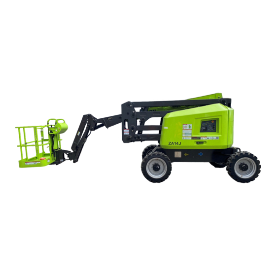
ZA14J (ZA45J)
Service and Maintenance Manual
Advertisement
Table of Contents

Subscribe to Our Youtube Channel
Related Manuals for Zoomlion ZA14J


Summary of Contents for Zoomlion ZA14J
- Page 1 Add:No.996 Tengfei Rd Wangcheng District Changsha Hunan P. R. China E-mail:awm@zoomlion.com Eel:400-800-0157 Open up the WeChat, Scan the QR code above; All rights reserved 2015 © Zoomlion,reserves all rights,Without the written permission of Zoomlion, the contents of any part of this sample may not be copied for any purpose.
- Page 3 Service and Maintenance Manual ZA14J (ZA45J) Service and Maintenance Manual Comply with ANSI SAIA_A92.20-2018 and CSA-B354.6-2017 Standard 2020.1 A...
-
Page 5: Foreword
Foreword This Service and Maintenance Manual applies to the ZA14J aerial work platform (hereinafter referred to as the AWP). This manual describes proper inspection, servicing and maintenance. Users must fully understand and apply the contents described in this manual to maximize the performance and ensure the long-term safe and efficient use. - Page 6 Foreword Symbols and their description: Danger indicates an imminently dangerous situation. If not avoided, will result in death or serious injury. Warning indicates a potential hazardous situation. If not avoided, will result in death or serious injury. Caution indicates a potential hazardous situation. If not avoided, will result in minor or moderate injury. Notice indicates information of property and device damage, or wrong operation.
-
Page 7: Table Of Contents
Contents Foreword ..............................I Content ..............................III SECTION 1 MAINTENANCE SAFETY INSTRUCTION ............1-1 1.1 Maintenance Personnel Duties, Requirements and Safety Equipment ..........1-1 1.1.1 Duties ..........................1-1 1.1.2 Basic requirements ......................1-1 1.1.3 Personnel safety equipment .................... 1-1 1.2 Maintenance Precautions ........................1-2 1.2.1 Precautions ........................ -
Page 8: Content
Contents 3.2 Maintenance and Service Instruction ....................3-2 3.2.1 General instruction ......................3-2 3.2.2 Safety and operating standards ..................3-3 3.2.3 Cleaning .......................... 3-3 3.2.4 Component disassembly and installation ................ 3-3 3.2.5 Component disassembly and reinstallation ..............3-3 3.2.6 Pressure-fit parts ......................3-3 3.2.7 Bearing .......................... - Page 9 Contents 4.1.3 Tire replacement ......................4-2 4.1.4 Wheel replacement ......................4-2 4.1.5 Wheel installation ......................4-2 4.2 Swing Axle Exhaust and Locking Test ..................... 4-3 4.2.1 Floating cylinder exhaust ....................4-3 4.2.2 Swing axle lock test ......................4-4 4.3 Chassis Angle Sensor System ......................4-5 4.4 Auxiliary Power System ........................
- Page 10 Contents SECTION 7 ELECTRICAL INFORMATION AND SCHEMATIC ..........7-1 7.1 General Introduction ......................... 7-1 7.2 Multimeter Basic Operation ......................7-1 7.2.1 Grounding ........................7-1 7.2.2 Backside detection ......................7-1 7.2.3 Minimum value/maximum value ..................7-1 7.2.4 Polarity ..........................7-1 7.2.5 Range ..........................7-2 7.2.6 Voltage measurement ......................
-
Page 13: Section 1 Maintenance Safety Instruction
SECTION ONE MAINTENANCE SAFETY INSTRUCTION 1.1 Maintenance Personnel Duties, Requirements and Safety Equipment 1.1.1Duties The maintenance personnel must maintain the aerial work platform and to be responsible for the safe use and normal operation. The Maintenance and Service Manual provided by the company shall be observed and all necessary maintenance shall be carried out under the safe working system. -
Page 14: Maintenance Precautions
Check safety equipment before and after work, perform maintenance according to specified procedures or replacement if necessary; Keep inspection and maintenance records if needed; Certain safety equipment (such as helmets and seat belts) might be damaged after prolonged use and should be inspected and replaced periodically. 1. -
Page 15: Precautions In Maintenance
of them must be in front of the turntable or platform control panel so that the engine can be shut down at any time if necessary, and others can conduct inspection or maintenance. Personnel should keep close contact to work safely; Clean the aerial work platform before inspection or maintenance. - Page 16 Figure 1-3 Mind explosion The positive and negative wires of the battery must be removed when welding to prevent the positive and negative poles of the welder from forming a loop with the unit body, thereby burning electrical components such as controllers and sensors. The company does not take the consequences for wrong operation.
- Page 17 It is strictly forbidden to disassemble electronic components. Do not allow tools or parts to fall into the inspection hole; do not allow objects to fall into the holes during work. Falling objects can damage the machine or cause the machine to malfunction. Any tools or objects that fall into the inspection hole must be removed;...
- Page 18 Inspection or maintenance of the electrical system without removing the cable of the battery may cause a short circuit and damage the wiring, electrical components and electronic components of the electrical system; The cable on the negative terminal side (ground side) must be removed before the inspection or maintenance work on the electrical system.
- Page 19 on the mechanically maintained parts; Restore or reset the safety device and recalibrate the safety device if necessary; Remove the tools and equipment for maintenance, replace parts and scattered objects, and clean up the site; It should always be borne in mind that all maintenance should include mandatory confirmation of normal mechanical movement.
-
Page 23: Section 2 Technical Parameters
SECTION 2 TECHNICAL PARAMETERS 2.1 Performance Table 2-1 Performance Platform capacity 300kg 661 lb 45% (platform uphill) Max travel speed (on slope) 25% (platform downhill) Max travel speed (side slope) Platform height 13.72m 45ft Horizontal outreach 7.62m 25ft 4.73 m (outside) 15ft 6in (outside) Turning radius 1.96 m (inside) -
Page 24: Capacity
2.3 Capacity Table 2-3 Capacity Fuel tank 65 L 17.17 us gal Hydraulic oil tank 74 L 19.55 us gal Engine oil capacity 2.11 us gal 2.4 Components Specification 2.4.1 Engine Table 2-4 D2.9L4 (Deutz) Engine specification Type Electric control Fuel No. -
Page 25: Battery
Table 2-6 404D-22 (Perkins) Engine specification Type Electric control Fuel No.0 National IV Engine oil capacity About 8 L (2.11us gal) 1200rpm (idling) Rotate speed 2000rpm (low speed) 2600rpm (high speed) Current output of generator 12V, 65A Horsepower Coolant Cold water, about 11L (2.91 us gal) 2.4.2 Battery Table 2-7 Battery specification Rated voltage... -
Page 26: Functional Speed
2.6 Functional Speed Table 2-9 Functional speed (Unit: s) Function ZA14J Upper boom lifting 24 s ~30 s Upper boom lowering 24 s ~30 s Turntable swing (a round) 60 s ~70 s Upper boom extending 10 s ~15 s... -
Page 27: Torque Requirements
The function speed may vary depending on the temperature and thickness of the hydraulic oil. When running the test, the hydraulic oil temperature must exceed 38℃/100.4℉; Some flow control functions may be disabled when the speed knob is positioned to low speed. 2.7 Torque Requirements Table 2-10 Torque requirements Strength grade and corresponding torque Nm... -
Page 28: Pressure Setting
2.9 Pressure Setting Table 2-12 Pressure setting Upper boom lifting 21MPa Upper boom extending 21MPa Turntable swing 12MPa Chassis diversion 18MPa Jib lifting 21MPa Platform rotation 21MPa Platform leveling 17MPa Tower boom lifting 21MPa... -
Page 31: Section 3 General Introduction
SECTION 3 GENERAL INTRODUCTION 3.1 Machine Preparation, Inspection and Maintenance 3.1.1 General introduction This section provides the necessary information to the operator responsible for pre-operational inspection and safe operation. In order to obtain the longest service life and ensure safe operation, all necessary inspections and maintenance should be completed before the machine is put into use. -
Page 32: Preventive Maintenance
inspection. Please refer to the relevant contents of this manual for maintenance and service procedures. To ensure that safety reports are obtained, our company needs to update the ownership information of each machine. Please inform us of the current machine ownership information each time the machine annual inspection is carried out. -
Page 33: Safety And Operating Standards
maintenance procedures contained in this manual. 3.2.2 Safety and operating standards Safety is paramount when performing equipment maintenance. Always pay attention to weight. Never attempt to move heavy parts without mechanical assistance. Do not park heavy objects in unstable locations. Ensure that adequate support is provided when lifting. 3.2.3 Cleaning Prevent dirt or impurities from entering critical parts of the machine for longer service lift. -
Page 34: Washer
bearings cannot be rotated; If the bearing race and the steel ball (or roller) are sunken, scratched or burnt, scrap the bearing; If the bearing is still serviceable, apply a layer of oil and wrap it in clean paper (or wax paper). Do not open the reusable or new bearing packaging until you are ready to install it;... -
Page 35: Lubrication And Maintenance
3-2 is not used to specify the type and parameters of hydraulic oil). Please select the hydraulic oil of the appropriate brand and technical parameters according to the specific use environment of the equipment. For special environments or users with special requirements, please contact ZOOMLION or hydraulic... - Page 36 oil manufacturers. Note: do not mix different brands or types of oils, and the mixing of additives in different oils will have negative impact. If hydraulic oil mixing is unavoidable, it must be approved by the hydraulic oil manufacturer. Our after-sales service does not take the consequence of the use of fluid mixing. Table 3-2 Hydraulic oil technical parameter Mobil Kunlun...
-
Page 37: Hydraulic Oil Replacement
safety of the components and the efficiency of the work, it is recommended that the starting temperature of the equipment is higher than the selected hydraulic oil pour point temperature of 25℃/77℉ or more. 3.3.3 Hydraulic oil replacement Good quality hydraulic fluids are critical to machine performance and service life. Unclean hydraulic fluid can affect machine performance and can cause damage to parts if used continuously. -
Page 38: Cylinder Drift
Measure drift from the platform to the ground. Raise the lower boom slightly (if equipped) and fully extend the upper boom with the platform capacity and power off; The maximum allowable drift in 10 minutes is 5 cm/2 inches. If the machine fails this test, please conduct the following operation. -
Page 39: Pin And Bearing Inspection Instruction
3.5 Pin and Bearing Inspection Instructions 3.5.1 Fiber bearing Disconnect and inspect the connecting pin when one of the following conditions occurs: Joint tilting; Noise is generated at the joint during operation. Fiber bearings should be replaced in one of the following situations: Wear or separate fibers on the surface of the liner;... -
Page 40: Use Insulating Grease In Electrical Connection Location
the grounded location and the weld zone. Violation of the above requirements may result in damage to components (such as electronic module, rotating bearing, collector ring, etc.) 3.7 Use Insulating Grease in Electrical Connection Locations Insulating silicone grease should be used for all electrical connections for the following reasons: Prevent the mechanical joint between the male and female pins from being oxidized;... - Page 41 damaged connections and repair if necessary; Check all harness connectors to ensure they are fully seated and locked; Check the ignition coil and spark plug cable for hardening, cracking, wear, separation, cracking of the dust cover, and proper meshing; Replace the spark plug at the time intervals specified in the engine manufacturer’s manual; Check and confirm that all electrical components are securely connected;...
- Page 42 Table 3-3 Inspection and preventive maintenance schedule Time intervals Pre-delivery Items Every 2 Pre-start Weekly Monthly Annually or daily years Boom assembly Boom weldment 1,2,4 1,2,4 Oil pipe/wire rope 1,2,9,12 1,2,9,12 Shaft pin and pin Pulley and pulley pins Bearings Wear pad Covers or shields Cables or wire...
- Page 43 Table 3-3 Inspection and preventive maintenance schedule (continuous) Time intervals Items Pre-delivery Every 2 Pre-start Weekly Monthly Annually or daily years Steer components Drive motor Torque hub Function/Control Platform control Ground control Function control locks, protective device or brake device Foot switch Emergency switch (Ground and platform)
- Page 44 Table 3-3 Inspection and preventive maintenance schedule (continuous) Time intervals Items Pre-delivery Every 2 Pre-start Weekly Monthly Annually or daily years Fluid reservoir, cap and 11,9 breather Hydraulic/Electrical system Hydraulic pump 1,2,9 Hydraulic oil tank 1,9,7 1,2,9 1,2,9 Cylinder pinned joints and pins retainer Hydraulic hose and other 1,2,9,12...
- Page 45 All system functional test 21, 22 Painting and appearance Imprint check date on the frame Notifying Zoomlion machine ownership Footnote: 1. Before daily use or each shift 2. Before each sale, rental or delivery 3. Use 3 months or 150 hours, or idle for more than 3 months, or buy as a used machine 4.
- Page 46 Performance code: 1 -Confirm that the installation is correct and secure 2 -Visually inspect for damage, cracks, deformation or excessive wear 3 -Check if the adjustment is correct 4 -Check for cracked or damaged welds 5 -Correct operation 6 -Return to neutral of OFF position when released 7 -Clean and free of dirt 8 -Interlock function 9 -Check for signs of leaks...
-
Page 49: Section 4 Chassis And Turntable
4.1.1 Tire inflation In order to endure the safety and normal operation, the air pressure of the pneumatic tire must be the same as the air pressure indicated on the side of the Zoomlion machines or the rim sticker. 4.1.2 Tire damage... -
Page 50: Tire Replacement
A smooth, uniform cut with a total length of more than 7.5cm/3 inches in the ply; Cracks (uneven edges) in any direction that exceed 2.5cm/1 inch in the ply; Perforations having a diameter of more than 2.5cm/1 inch; Any damage to the ply of the tire bead. If the tire is damaged but still within the above criteria, the tire must be inspected daily to ensure that the damage does not exceed the permissible standard. -
Page 51: Swing Axle Exhaust And Locking Test
Figure 4-2 Wheel fastening nut tightening sequence Nut tightening should be carried out in steps. Please refer to the wheel torque table and tighten the nuts in the recommended order; Table 4-1 Wheel torque table Torque application sequence First step Second step Third step 75 Nm/54.3 ft·lb... -
Page 52: Swing Axle Lock Test
Figure 4-3 Exhaust valve connector position 4.2.2 Swing axle lock test Locking system testing must be performed quarterly when components of the locking system are replaced or improper system operation conducted. Note: before starting the floating cylinder test, make sure the boom is fully retracted, lowered and centered in the middle of the two drive wheels. -
Page 53: Chassis Angle Sensor System
Repeat the above steps to operate the right front wheel; If the function of the floating cylinder is abnormal, contact the qualified personnel to correct the malfunction, then perform other operations. 4.3 Chassis Angle Sensor System The chassis angle sensor system is used to measure the angle of the turntable relative to the chassis. The control system reads the sensor reading and compares the reading to a preset turntable angle value. -
Page 54: Traveling Drive System
control will cut off the power supply, which will cause the swing front axle to lock in an unsafe state until it is re-powered. Figure 4-4 Floating cylinder disassembly diagram 4.6 Traveling Drive System The traveling system is mainly composed of wheels, traveling reducer and traveling motor. Specifically, the four-wheel drive system consists of a variable displacement closed pump, four variable displacement piston motors, four gear reducers, and a split/flow-combining travel control valve. -
Page 55: Travel Reducer
Figure 4-5 Travel system disassembly diagram 1 Figure 4-6 Travel system disassembly diagram 2 4.7 Travel Reducer 4.7.1 Disassembly Place the machine on a solid level surface; Remove all hydraulic lines connected to the travel motor on the travel reducer and close the port; Use a suitable lifting device to support the travel reducer. -
Page 56: Installation
Disassemble the six bolts used to connect the travel reducer and the chassis structure; Remove the travel reducer from the equipment and place it in a clean work area. Figure 4-7 Travel reducer disassembly diagram 4.7.2 Installation Use a suitable lifting device to support the travel reducer. The travel reducer weighs approximately 50kg/110 lb;... -
Page 57: Traveling Motor
4.8 Traveling Motor 4.8.1 Disassembly Place the machine on a solid level surface; Remove all hydraulic connections to the traveling motor and mark them; Use a suitable lifting device to support the traveling motor. The traveling motor weights approximately 15.4kg/34 lb; Disassemble the two mounting bolts used to connect the traveling motor to the steering knuckle;... -
Page 58: Generator
torque reaches 95Nm/68.7 ft·lb; Reinstalling the previously removed hydraulic line connected to the traveling motor; Start the unit and check the function of the traveling motor. 4.9 Generator Every 250 hours; Check that the drive belt tension is appropriate every 250 hours of operation. Every 500 hours;... - Page 59 open, the generator will stop outputting. If the circuit breaker remains open, check the equipment connected to the platform socket for any malfunction. Check the carbon brush, replace the carbon brush, clean the slip ring Check the carbon brush position; Check that the carbon brush is aligned with the slip ring.
-
Page 63: Section 5 Boom And Platform
SECTION 5 BOOM AND PLATFORM 5.1 Platform and Jib 5.1.1 Load cell 5.1.1.1 Disassembly Figure 5-1 Load cell disassembly diagram Retract the tower boom and the upper boom; Disconnect the wiring harness at the platform control box and the load cell, disconnect the pipeline at the platform valve, and mark it at the same time;... -
Page 64: Rotary Actuator Disassembly
installation should be cleaned to prevent contaminants from entering the hydraulic system; Threaded fasteners should be tightened in place according to the torque values in Section 2 Specifications. 5.1.2 Rotary actuator 5.1.2.1 Disassembly Figure 5-2 Jib lifting cylinder disassembly diagram Disconnect the hydraulic line connecting the rotary actuator balancing valve, collect the hydraulic oil in the pipeline with a suitable container, and seal the port of the pipeline after collecting;... -
Page 65: Boom Assembly
collecting; Remove the connecting bolts 3 and 5 of the support and the upper and lower links, and remove the pins 4 and 6, so that the jib lifting cylinder can be removed. 5.1.3.2 Inspection Check the line for wear and replace the wiring harness if necessary; Check hydraulic oil leaks and replace the line if necessary;... -
Page 66: Cable Disassembly
5.2.1 Cable 5.2.1.1 Disassembly Figure 5-3 Cable system disassembly Adjusting the boom to a fully retracted state; Disconnect the pipeline from the ground control box; Mark and disconnect the hydraulic lines from upper boom to the control valve. Collect the hydraulic oil in the pipeline with a suitable container, and seal the port of the pipeline after collecting;... - Page 67 replace if necessary; Check the cable structure for bending, cracking, weld separation or other damage and replace the cable structure if necessary. 5.2.1.3 Installation Follow the reverse steps of disassembly. The pipe joints of the hydraulic lines before installation should be cleaned to prevent contaminants from entering the hydraulic system. A hydraulic system pipe joint equipped with a sealing device needs to replace a sealing device before the hydraulic line is connected;...
-
Page 68: Lower Leveling Cylinder And Lifting Cylinder
Inspect the shaft pin for wear, scratches, taper, ovality or other damage and replace the pin if necessary; Inspect the inner ring of the bearing for scratches, distortion, wear or other damage and replace the bearing if necessary; Inspect all threaded parts for damage such as stretching, thread deformation or distortion and replace if necessary. - Page 69 Use a suitable lifting device to support the tower boom to prevent the upper boom from falling when disassembling the other cylinder; Use suitable lifting equipment to hang the two ends of the upper boom lifting cylinder, disassemble the pin shaft 4 and the pin shaft 2 respectively, and remove the upper boom lifting cylinder; Use a suitable plug to block the connector of the main leveling cylinder balancing valve to prevent dust and other pollutants from entering the oil line.
- Page 70 5.2.4.1 Disassembly Figure 5-7 Upper boom disassembly diagram Before disassembling the upper boom, it is necessary to disassemble working platform, jib, cable, upper leveling cylinder, counterweight (weight about 1800kg/3968 lb) and hood, according to the disassembly steps; Fully retract the upper boom to the horizontal position; Use the appropriate lifting equipment to hang the upper boom (weight about 400kg/882 lb).
-
Page 71: Telescopic Cylinder Disassembly
5.2.5 Telescopic cylinder 5.2.5.1 Disassembly Figure 5-8 Telescopic cylinder disassembly diagram Need to unload the working platform, jib, cable, upper leveling cylinder, counterweight (weight about 1800kg/3968 lb), hood and upper boom according to the disassembly steps; Disassemble the hood and two stroke switches at the tail of the telescopic cylinder; Mark and disconnect the hydraulic line connecting the two cylinders balancing valve, collect the hydraulic oil in the pipeline with a suitable container, and seal the port of the pipeline after collecting;... -
Page 72: Tower Boom And Its Cylinder Disassembly
5.2.5.3 Installation Follow the reverse steps of disassembly. The interface of the hydraulic pipe joint and balance valve before installation should be cleaned to prevent contaminants from entering the hydraulic system; A hydraulic system pipe joint equipped with a sealing device needs to replace a sealing device before the hydraulic line is connected;... - Page 73 Lift the upper upright with lifting equipment, remove the pin 3 and 4, and hang it; Lift the upper linkage with lifting equipment, remove the pin 5, and hang it; Lift the tower boom cylinder with lifting equipment, remove the pin 12 and 11 and then hang it; Lift the pull rod with the lifting device, remove the pin 6 and 7 and then hang it;...
-
Page 77: Section 6 Electrical System Maintenance
SECTION 6 ELECTRICAL SYSTEM MAINTENANCE 6.1 Fault Code When the unit fails, check the fault message indicated by the display on the ground console. If the display on the ground console indicates the following fault code, remove the fault condition and restart the device before continuing operation. - Page 78 Table 6-1 Fault code list (continuous) Classification Fault code Fault code list 22359 Dtc_Fault_Ug_Swing_Switch_Double_Power_On 22360 Dtc_Fault_Ug_Engine_Switch_Double_Power_On 14361 Dtc_Fault_Pm_Main_Lift_Joystick_Double_Power_On 14363 Dtc_Fault_Pm_Jib_Switch_Double_Power_On 14364 Dtc_Fault_Pm_Telescope_Double_Power_On 24365 Dtc_Fault_Pm_Rotate_Switch_Double_Power_On 14366 Dtc_Fault_Pm_Leveling_Switch_Double_Power_On 24367 Dtc_Fault_Pm_Swing_Joystick_Double_Power_On 24368 Dtc_Fault_Pm_Engine_Switch_Double_Power_On 14369 Dtc_Fault_Pm_Drive_Joystick_Double_Power_On 14370 Dtc_Fault_Pm_Steer_Joystick_Double_Power_On 14371 Dtc_Fault_Ug_Footswitch_Closed 14372 Dtc_Fault_Footswitch_Function Switch/handle 14373 Dtc_Fault_Pm_Drive_Direction_Confirm_Switch 24374 Dtc_Fault_Pm_Drive_Speed_Geer_Switch...
- Page 79 Table 6-1 Fault code list (continuous) Classification Fault code Fault code list 21560 Dtc_Float_Control_Valve_Short_To_Power 21561 Dtc_Float_Control_Valve_Open_Circuit 21562 Dtc_Brake_Valve_Short_To_Ground 11563 Dtc_Brake_Valve_Short_To_Power 21564 Dtc_Brake_Valve_Open_Circuit 21565 Dtc_2speed_Valve_Short_To_Ground 21566 Dtc_2speed_Valve_Short_To_Power 21567 Dtc_2speed_Valve_Open_Circuit 22568 Dtc_Steer_Left_Valve_Short_To_Ground 12569 Dtc_Steer_Left_Valve_Short_To_Power 22570 Dtc_Steer_Left_Valve_Open_Circuit 22571 Dtc_Steer_Right_Valve_Short_To_Ground 12572 Dtc_Steer_Right_Valve_Short_To_Power 22573 Dtc_Steer_Right_Valve_Open_Circuit 22574 Dtc_Swing_Left_Valve_Short_To_Ground 22575...
- Page 80 Table 6-1 Fault code list (continuous) Classification Fault code Fault code list 13602 Dtc_Telescope_Valve_Short_To_Power 23603 Dtc_Telescope_Valve_Open_Circui 23604 Dtc_Hand_Leveling_Valve_Short_To_Ground 13605 Dtc_Hand_Leveling_Valve_Short_To_Power 23606 Dtc_Hand_Leveling_Valve_Open_Circuit 23607 Dtc_Jib_Valve_Short_To_Ground 13608 Dtc_Jib_Valve_Short_To_Power 23609 Dtc_Jib_Valve_Open_Circuit 23610 Dtc_Main_Lift_Dn_Safe_Vavle_Short_To_Ground 13611 Dtc_Main_Lift_Dn_Safe_Valve_Short_To_Power Valve 23612 Dtc_Main_Lift_Dn_Safe_Valve_Open_Circuit 23613 Dtc_Main_Lift_Dn_Speed_Valve_Short_To_Groun 23614 Dtc_Main_Lift_Dn_Speed_Valve_Short_To_Power 23615 Dtc_Main_Lift_Dn_Speed_Valve_Open_Circuit 23617 Dtc_Tower_Lift_Dn_Safe_Valve_Short_To_Ground...
-
Page 81: Common Faults And Solutions
6.2 Common Faults and Solutions Table 6.2 Common faults and solutions Fault Feature Fault Cause Solution Remove the battery or replace it with a 1. Battery exhausted new one. 2. Operation switch or Push the operating switch or handle handle is not returned to back to the neutral position neutral position 3. - Page 82 Replace controller 1. If you encounter any equipment failure, contact Zoomlion for timely troubleshooting; 2. If there is no absolute understanding of the fault resolution, please contact Zoomlion or Zoomlion dealers to solve it; 3. It is forbidden to open the electric control cabinet to change the wire.
-
Page 85: General Introduction
SECTION 7 ELECTRICAL INFORMATION AND SCHEMATIC 7.1 General Introduction This section introduces basic electrical information and schematics for locating and correcting most operational problems that may arise. If problems that are not listed in this section or not be corrected by the listed solutions, occur, you should obtain authoritative technical guidance before performing maintenance. -
Page 86: Range
leads are reversed. Check the voltage prediction value, signal position, and whether the lead is properly connected to the device under test. Also check that the lead of the COM port is grounded or the negative signal is connected, and that the lead of the other port is connected to the positive signal. 7.2.5 Range M = mega = 1,000,000 * (displayed number);... -
Page 87: Current Measurement
First test the multimeter and leads by touching the two leads. The result should show a short circuit of resistance (very low resistance); The circuit power must be turned off before testing the resistor; Disconnect each component from the circuit before testing; If the multimeter cannot automatically adjust the range, set the correct range (refer to the multimeter operation manual);... -
Page 88: Deutsch Connector
Set the expected current range of the multimeter; Verify that the multimeter leads and jacket are properly connected within the current range of your choice; If the multimeter cannot automatically adjust the range, set the correct range (refer to the multimeter operation manual);... -
Page 89: Dt/Dtp Series Connector Disassembly
7.3.2 DT/DTP Series Connector Disassembly Figure 7-6 DT/DTP contact removal When disassembling, use a non-toothed nose pliers or hook line to pull the wedge locker vertically; Use a screwdriver to remove the retaining finger from the contact, release the retaining finger, and gently pull the wire to remove the contact;... - Page 90 that the connector is fully locked. Figure 7-8 HD/HDP lock contact position Note: for unused wire cavities, a sealing plug should be inserted to achieve complete isolation from the environment. 7.3.4 HD30/HDP20 Series Connector Removal Figure 7-9 HD/HDP contact removal With the rear insert facing the side, select the appropriate size of the insertion and removal tool to clamp the wire of the contact to be removed;...
- Page 91 Figure 7-10 HD/HDP non-locking contact Note: for unused wire cavities, a sealing plug should be inserted to achieve complete isolation from the environment.
-
Page 92: Electrical Schematics
7.4 Electrical Schematics Figure 7-11 Electrical schematics (Figure 1/6)... - Page 93 Figure 7-12 Electrical schematics (Figure 2/6)
- Page 94 Figure 7-13 Electrical schematics (Figure 3/6) 7-10...
- Page 95 Figure 7-14 Electrical schematics (Figure 4/6) 7-11...
- Page 96 Figure 7-15 Electrical schematics (Figure 5/6) 7-12...
- Page 97 Figure 7-16 Electrical schematics (Figure 6/6) 7-13...
-
Page 98: Hydraulic Schematics
7.5 Hydraulic Schematics Figure 7-17 Hydraulic schematics (Figure 1/2) 7-14... - Page 99 Figure 7-18 Hydraulic schematics (Figure 2/2) 7-15...
Need help?
Do you have a question about the ZA14J and is the answer not in the manual?
Questions and answers
Аккумуляторная батарея не держит заряд. Батарея исправна, может подключение произвели не правильно при замене АКБ?