Table of Contents
Advertisement
Quick Links
Advertisement
Table of Contents
Troubleshooting

Related Manuals for Keysight Technologies M5302A


Summary of Contents for Keysight Technologies M5302A
- Page 1 M5302A PXIe LVDS Digital IO Modules 28 LVDS Channels, 8 Trigger IO Startup Guide...
- Page 2 ALL WARRANTIES, EITHER EXPRESS OR which is embodied in its End User License met. IMPLIED WITH REGARD TO THIS MANUAL Agreement (EULA), a copy of which can AND ANY INFORMATION CONTAINED M5302A PXIe LVDS Digital IO Modules Startup Guide...
-
Page 3: Safety Summary
Failure to comply with these precautions or with specific warnings or operating instructions in the product manuals violates safety standards of design, manufacture, and intended use of the instrument. Keysight Technologies assumes no liability for the customer's failure to comply with these requirements. Product manuals are provided on the Web. - Page 4 Normally only dry non-conductive pollution occurs. Occasionally a temporary conductivity caused by condensation may occur. Example: General indoor environment. Conductive pollution occurs, or dry, non-conductive pollution occurs which becomes conductive due to condensation which is expected. Example: Sheltered outdoor environment. M5302A PXIe LVDS Digital IO Modules Startup Guide...
-
Page 5: Safety Symbols & Instrument Markings
This is the Keysight email address required by EU directives applicable to our product. M5302A PXIe LVDS Digital IO Modules Startup Guide... -
Page 6: Compliance And Environmental Information
Declarations of Conformity for this product and for the Keysight products may be downloaded from the Web. Go to http://www.keysight.com/go/conformity. You can then search by product number to find the latest Declaration of Conformity. M5302A PXIe LVDS Digital IO Modules Startup Guide... -
Page 7: In This Guide
In this Guide This guide provides you the information to begin using the M5302A PXIe LVDS Digital IO Modules. • Chapter 1, “Overview on M5302A PXIe LVDS Digital IO Modules” provides an overview of the M5302A PXIe LVDS Digital IO Module hardware and software along with an overview of the applications that enhance the module’s functionality. - Page 8 M5302A PXIe LVDS Digital IO Modules Startup Guide...
-
Page 9: Table Of Contents
Safety symbols & instrument markings Compliance and Environmental Information Declaration of Conformity In this Guide 1 Overview on M5302A PXIe LVDS Digital IO Modules About this document About M5302A Digital IO modules Key features in the M5302A modules About the 100-pin LVDS connector... - Page 10 Toggling signal states Conducting Self test Cleaning the module 3 Setting up the M5302x software Prerequisites to setting up M5302x software System requirements Prerequisite software requirements Obtaining License Options Downloading required software M5302A PXIe LVDS Digital IO Modules Startup Guide...
- Page 11 4 Troubleshooting and Safety information Troubleshooting installation issues Troubleshooting issues with Python Installing M5302x Drivers on Python ver. other than 3.7 Installing Python after the Instrument Driver Safety information General safety considerations M5302A PXIe LVDS Digital IO Modules Startup Guide...
- Page 12 Contents M5302A PXIe LVDS Digital IO Modules Startup Guide...
-
Page 13: Overview On M5302A Pxie Lvds Digital Io Modules
M5302A PXIe LVDS Digital IO Modules Startup Guide Overview on M5302A PXIe LVDS Digital IO Modules / 14 About this document / 15 About M5302A Digital IO modules / 21 About M5302x software features / 22 About PathWave FPGA and BSP... -
Page 14: About This Document
Section 1.1: About this document This document helps you get started with a brief introduction to the M5302A PXIe LVDS Digital IO module along with its associated software components. It also serves as a guide for the required preliminary setup followed by procedures to install the Keysight M5302A PXIe Module SFP and API along with its extended components. -
Page 15: About M5302A Digital Io Modules
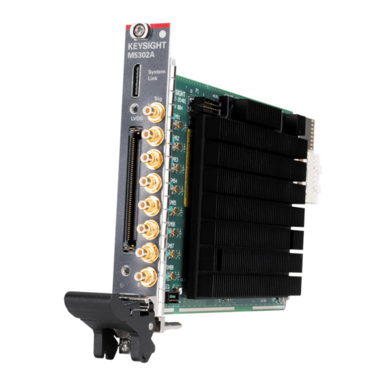
Overview on M5302A PXIe LVDS Digital IO Modules Section 1.2: About M5302A Digital IO modules M5302A is a single-slot Digital I/O PXIe module with 28 programmable LVDS channels and 8 single-ended digital I/O channels. The LVDS channels can be used to communicate to the device under test or can be used to control other devices by emulating protocols such as Camera Link. -
Page 16: Key Features In The M5302A Modules
Overview on M5302A PXIe LVDS Digital IO Modules Table 2 describes the connectors labeled in Figure Table 2 M5302A connectors and their description Label# Description 100-pin, front panel connector, including 28 bidirectional differential I/O channels. These differential signals are LVDS (meant to drive 100-ohm differential load) and have a 1.2 Gbps maximum toggle rate. -
Page 17: About The 100-Pin Lvds Connector
Overview on M5302A PXIe LVDS Digital IO Modules 1.2.2: About the 100-pin LVDS connector The 100-pin front panel connector on the M5302A PXIe LVDS Digital IO module includes: 28 bidirectional channels for Low Voltage Differential Signals (LVDS) Two Tx Disable controls for Device Safety... - Page 18 Overview on M5302A PXIe LVDS Digital IO Modules Figure 2 Pin-out diagram for the 100-pin LVDS connector on M5302A module M5302A PXIe LVDS Digital IO Modules Startup Guide...
- Page 19 FPGA is configured. The LVDS_TXDISABLEn_IN line must be manually driven high before the M5302A module attempts to drive any of the LVDS channels that are configured as outputs unless you override this condition by setting the DifferentialChannels.OutputSafetyState() API to ‘Disabled’.
-
Page 20: Equipment Supported With M5302A Modules
(SMB Plug to SMB Plug Cable 12 Inch Length Using RG316-DS Coax, RoHS) Breakout Board for IO * The connector on the M5302A module is 1254-4244, which is ERF8-RA from Samtec: ERF8-050-01-L-D-RA-L-TR. You can plug into this connector with a cable or a plug-in board using the correct Samtec mate (ERM8 for a board, ERCD or ERDP for a cable). -
Page 21: About M5302X Software Features
Section 1.3: About M5302x software features The Keysight M5302x software, which comprises of drivers, programming libraries and Software Front Panel for the M5302A module, provides a comprehensive platform to perform the basic operations pertaining to Digital IO modules. The M5302x software also supports the Hardware FPGA reprogramming, which is done using the PathWave FPGA Board Support Package. -
Page 22: About Pathwave Fpga And Bsp
1.4.2: Using BSP with PathWave FPGA PathWave FPGA, by itself, does not provide access to any of the controls, which are associated with the Keysight M5302A PXIe modules. You must install the Board Support Package (BSP) to leverage the features within the PathWave FPGA software for your design. - Page 23 PathWave FPGA software. Both PathWave FPGA software and the BSP function together and cannot be used individually. To control the front panel IO on the M5302A modules, the M5302x API allows you to control the hardware. The hardware license option -PWP must be available on the M5302A NOTE modules for the implementation of PathWave FPGA BSP.
-
Page 24: About Ks2201A Pathwave Test Sync Executive Software
When creating an HVI, you can include any instrument, similar to Keysight’s M5302A PXIe LVDS Digital IO modules, that has HVI support. M5302A PXIe LVDS Digital IO Modules Startup Guide... -
Page 25: M5302A Firmware Version Requirements For Hvi
1. Firmware upgrade/downgrade and M5302x software upgrade/downgrade can be performed manually. There is no need to return the module to Keysight. 2. Note that option HV2 on the M5302A modules is required for operation with KS2201A. 1.5.3: About HVI Application Programming Interface... - Page 26 HVI instrument extensions to enable instrument functionalities in an HVI. The hardware license option -HV2 must be available on each M5302A NOTE module that is required to be programmed using the KS2201A PathWave Test Sync Executive software.
-
Page 27: References To Help Documents
Overview on M5302A PXIe LVDS Digital IO Modules Section 1.6: References to Help documents Table 5 Reference document titles and access links Document Reference Filename / Format Reference location M5302A PXIe LVDS Digital IO Modules Startup Guide M5302A PXIe LVDS Digital IO Modules Security Guide https://www.keysight.com/find/M5302A-TechSupport... - Page 28 Overview on M5302A PXIe LVDS Digital IO Modules M5302A PXIe LVDS Digital IO Modules Startup Guide...
-
Page 29: Setting Up The M5302A Module
M5302A PXIe LVDS Digital IO Modules Startup Guide Setting up the M5302A module / 30 Unpacking, Inspecting and Verifying the shipment / 33 Installing the PXIe Module / 43 Verifying M5302A module’s operation... -
Page 30: Unpacking, Inspecting And Verifying The Shipment
Inspect the carton carefully for any damage, or signs of rough handling. Remove the M5302A module from the packaging container and ensure that all accessories are included. Inspect the module and accessories for damage. If the contents appear damaged, notify your local Keysight Technologies Inc. -
Page 31: Verifying Shipment Of M5302A Module
(Refer to the warranty information at beginning of this document). To avoid damage when handling the M5302A module, do not touch CAUTION exposed connector pins. -
Page 32: Returning The Module For Service
Keysight equipment. 2.1.4: Returning the Module for Service If you find it necessary to return the M5302A module for repair or service, follow the steps below: The M5302A is factory tested, aligned, adjusted, and shipped as a single NOTE module. -
Page 33: Installing The Pxie Module
Before installing or removing a module to/from the chassis, power down the chassis to prevent damage to the module. Best practices for cooling chassis and M5302A module The following are the recommended best practices to ensure proper and safe module operating conditions: •... - Page 34 • If you have multiple M5302A modules and space is available in your chassis, leave an empty slot between modules to enhance airflow. Ensure that a slot blocker and a filler panel are installed in the empty slots.
-
Page 35: Preparing The Pxie Chassis
Make sure that the PXIe chassis fans are operable and free of dust and other contaminants that may restrict airflow. M5302A PXIe LVDS Digital IO Modules Startup Guide... -
Page 36: Installing The Embedded Controller
Remove the M9037A module from its ESD protective bag. See “Precautions against ESD” on page 30. Install the embedded controller in Slot 1 (see the icon above the slot) in the chassis. M5302A PXIe LVDS Digital IO Modules Startup Guide... - Page 37 Tighten the module retaining screws (top and bottom) and torque them to 5 Lb-In (0.57 N-m). Install a blank Y1213A filler panel in the empty slot to the left of the controller. Connect peripherals (mouse, keyboard, and monitor). M5302A PXIe LVDS Digital IO Modules Startup Guide...
-
Page 38: Connecting A Remote Controller Pc To The Chassis
• Tighten the module retaining screws (top and bottom) and torque them to 5 Lb-In (0.57 N-m). M5302A PXIe LVDS Digital IO Modules Startup Guide... -
Page 39: Installing Slot Blockers And Filler Panels
2.2.5: Installing Slot Blockers and Filler Panels To assure proper operating temperatures, install slot blockers (Keysight model Y1212A, 5 per kit) and EMC filler panels (Keysight model Y1213A, 5 per kit) in empty module slots. M5302A PXIe LVDS Digital IO Modules Startup Guide... -
Page 40: Installing The Module
5 Lb-In (0.57 N-m). Figure 12 Depiction of installing a PXIe module The image above shows generic module installation. It may not reflect NOTE your module’s actual size and chassis placement. M5302A PXIe LVDS Digital IO Modules Startup Guide... -
Page 41: Powering Up The Chassis And Remote Controller Pc
PXIe hardware does not support “hot-swap” (changing modules while CAUTION power is applied to the chassis) capabilities. Before installing or removing a module to/from the chassis, power down the chassis to prevent damage to the module. M5302A PXIe LVDS Digital IO Modules Startup Guide... -
Page 42: Installing Required Software
2.2.8: Installing required software After the PC boots up and Windows desktop appears, you must install the software required for programming the M5302A modules. See Chapter “Setting up the M5302x software”. M5302A PXIe LVDS Digital IO Modules Startup Guide... -
Page 43: Verifying M5302A Module's Operation
2.3.1: Verifying M5302A connection The Keysight Connection Expert (installed with IO Libraries Suite) helps you check the connection of the M5302A Digital IO modules. To check if the module and its slot location are visible in the Keysight Connection Expert, click Start > Keysight Connection Expert. - Page 44 M5302A module connection status. Click Start > Keysight M5302x PCIe Module > M5302x SFP (x64). The “Connect to Instrument” window appears by default and if connected, it displays the M5302A modules along with the respective slots and VISA address. Figure 15...
-
Page 45: Toggling Signal States
TRIG 1 on the hardware) has been set from I (input) 0 (low) to O (output) 1 (high). Figure 16 Changing SMB IO S1 signal state on M5302x SFP Figure 17 shows that the toggling of signal state on Channel 1 of the Oscilloscope. M5302A PXIe LVDS Digital IO Modules Startup Guide... - Page 46 If you do not see the signal state toggling, try one of the following steps: • Check connection between module and Oscilloscope. • Connect another port on the M5302A module to the same or another Channel on the Oscilloscope. • Remove and reinstall the M5302x software.
-
Page 47: Conducting Self Test
Setting up the M5302A module 2.3.3: Conducting Self test The next step in this process is to conduct a Self Test of the M5302A module. Click Start > Keysight M5302x PCIe Module > M5302x SFP (x64) to launch the M5302x SFP. - Page 48 Setting up the M5302A module Figure 19 Viewing module connections in M5302x SFP On the Self Test window that appears, click Run Self Test. Figure 20 Starting Self test on the selected M5302A module M5302A PXIe LVDS Digital IO Modules Startup Guide...
- Page 49 If the self test is successful, the Self Test window appears as shown below. Figure 21 Self test passed status on the selected M5302A module Click Close to exit the Self Test window. If the Self Test fails, it indicates that the module likely needs service. In such cases, you must return the faulty module.
-
Page 50: Cleaning The Module
Power off the chassis and remove the M5302A module. Use either a dry lint free cloth, or compressed air to clean the front plate (face-plate) only of the M5302A module. -
Page 51: Setting Up The M5302X Software
M5302A PXIe LVDS Digital IO Modules Startup Guide Setting up the M5302x software / 52 Prerequisites to setting up M5302x software / 56 Obtaining License Options / 57 Downloading required software / 58 Installing required software / 70 Launching the software... -
Page 52: Prerequisites To Setting Up M5302X Software
General installation steps for prerequisite software Perform these steps for installing the software in the sequence shown in Table Click the download link and save the installer. Run the downloaded installer. Follow the on-screen instructions. M5302A PXIe LVDS Digital IO Modules Startup Guide... - Page 53 (recommended)” and “Add Python 3.7 to PATH” are checked. By default, the check box for the former option is selected and it is clear for the latter option. Click “Install Now” to install the required Python libraries. M5302A PXIe LVDS Digital IO Modules Startup Guide...
- Page 54 Launch the command prompt. b On the root directory, type python and press <Enter>. See Figure The version information of the current Python installation is displayed. Figure 24 Python installation verification on command prompt window M5302A PXIe LVDS Digital IO Modules Startup Guide...
- Page 55 5b and 6. The procedure for downloading and installing the M5302x software, Module firmware, PathWave FPGA Board Support Package and KS2201A PathWave Test Sync Executive software are described further in this chapter. M5302A PXIe LVDS Digital IO Modules Startup Guide...
-
Page 56: Obtaining License Options
Xilinx Vivado Design Suite (2017.3 or later) Refer to PathWave FPGA Customer Documentation for licensing info. Table 9 Hardware License Options Matrix supported by M5302x software Option description License name FPGA Programming -PWP HVI Programming -HV2 M5302A PXIe LVDS Digital IO Modules Startup Guide... -
Page 57: Downloading Required Software
KS2201A PathWave Test Sync Executive software Click here to visit page. KF9000A PathWave FPGA Programming Environment (commonly known as Click here to visit page. PathWave FPGA 2020 Update 1.0 or later) M5302A PXIe LVDS Digital IO Modules Startup Guide... -
Page 58: Installing Required Software
52 are installed on the same machine. 3.4.1: Installing Keysight M5302x software After you have downloaded the executable file from Keysight.com, double-click the installer for M5302x Software. Figure 26 Icon for the M5302x software installer M5302A PXIe LVDS Digital IO Modules Startup Guide... - Page 59 Welcome window on the M5302x InstallShield Wizard Click Next >. The License Agreement window is displayed. Figure 28 License Agreement window on the M5302x InstallShield Wizard From the Do you accept this license? options, select Agree. M5302A PXIe LVDS Digital IO Modules Startup Guide...
- Page 60 Setup Type window on the M5302x InstallShield Wizard By default, “Complete” is selected. Click Next >. The Setup Status window is displayed. Figure 30 Setup Status window on the M5302x InstallShield Wizard M5302A PXIe LVDS Digital IO Modules Startup Guide...
- Page 61 Completion window on the M5302x InstallShield Wizard Click Finish to complete the software installation and exit the M5302x Setup Wizard. If prompted to restart your machine, click Yes to continue (recommended) or No to restart the machine later. M5302A PXIe LVDS Digital IO Modules Startup Guide...
-
Page 62: Installing M5302A Module Firmware Updates
The Keysight M5302x software must be installed to update your module firmware. Downloading the Firmware The latest firmware for the M5302A module is included in the Keysight M5302x software package. Modifying the Firmware Based on your programming requirements, you may either upgrade or downgrade the Firmware version on a M5302A module. -
Page 63: Installing Ks2201A Pathwave Test Sync Executive Sw
Refer to the KS2201A PathWave Test Sync Executive User Guide for installation instructions and to know about the licenses that you must procure for the KS2201A PathWave Test Sync Executive software. M5302A PXIe LVDS Digital IO Modules Startup Guide... -
Page 64: Installing Pathwave Fpga Software
M5302x software. Contact Keysight Support for more information on procuring the respective licenses. After you have downloaded the executable file from Keysight.com, double-click the installer for PathWave FPGA software. Figure 33 Icon for the PathWave FPGA software installer M5302A PXIe LVDS Digital IO Modules Startup Guide... - Page 65 The Welcome window on the PathWave FPGA 2021 Setup Wizard appears. Figure 34 Welcome window in the PathWave FPGA Setup Wizard Click Next >. The License Agreement window is displayed. Figure 35 License Agreement window in the PathWave FPGA Setup Wizard M5302A PXIe LVDS Digital IO Modules Startup Guide...
- Page 66 From the Do you accept this license? options, select I accept the agreement. Click Next >. The Installation Directory window is displayed. Figure 36 Select Components window in the PathWave FPGA Setup Wizard If required, modify the installation directory path (not recommended). M5302A PXIe LVDS Digital IO Modules Startup Guide...
- Page 67 Figure 37 Ready to Install window in the PathWave FPGA Setup Wizard Click Next >. The installation progress window is displayed. Figure 38 Installation progress window in the PathWave FPGA Setup Wizard M5302A PXIe LVDS Digital IO Modules Startup Guide...
- Page 68 The completion window in the PathWave FPGA Setup Wizard is displayed. Figure 39 Completion window in the PathWave FPGA Setup wizard Click Finish to complete the software installation and exit the PathWave FPGA Setup Wizard. M5302A PXIe LVDS Digital IO Modules Startup Guide...
-
Page 69: Installing M5302A Bsp
Setting up the M5302x software 3.4.5: Installing M5302A BSP The latest BSP file required to design the M5302A module’s FPGA is included in the Keysight M5302x software package. There is no separate BSP installer for M5302A modules. The M5302A BSP can be accessed only within the PathWave FPGA Design Environment and not separately. -
Page 70: Launching The Software
Once you have installed the Keysight M5302x software, you can launch the Soft Front Panel (SFP) from the Start menu. On your Win10 OS, click Start > Keysight M5302x PCIe Module > M5302x SFP (x64). Figure 40 Launching SFP from the Start Menu M5302A PXIe LVDS Digital IO Modules Startup Guide... - Page 71 Setting up the M5302x software The Connect to Instrument window is displayed, as shown in Figure 41 Figure Figure 41 Default window without any active cards Figure 42 Default window with active cards M5302A PXIe LVDS Digital IO Modules Startup Guide...
- Page 72 As shown in Figure 42, while launching, the Keysight M5302x software auto-detects any active M5302A cards that are connected to the chassis. All such cards are displayed along with the chassis, slot number and VISA address on the Connect to Instrument window.
- Page 73 Setting up the M5302x software Note that a demo ‘M5302A’ module only is displayed in Figure 41 and in Figure 42 along with other active cards. This entry appears when “Simulation Mode” is enabled only, irrespective of state of the chassis (On / Off) or the modules inserted in them.
- Page 74 “Connected to <VISA address>” in the status bar on the main window For more information regarding the features and functionality of the Keysight M5302x SFP, refer to the M5302A PXIe LVDA Digital IO Modules User’s Guide, which can be accessed via the Help menu of the M5302x SFP.
-
Page 75: Starting M5302X Api
Import required system components and python libraries (as needed). Examples: import sys import os import numpy as np # For keysight_ktm5302x arrays Import the M5302x Python library for programming the M5302A card. Example: import keysight_ktm5302x as m5302x Proceed with creating module objects and defining other M5302x functions. -
Page 76: Initiating The Hvi Application
Import required system components and python libraries (as needed). Examples: import sys import os import numpy as np # For keysight_ktm5302x arrays Import the M5302x Python library for programming the M5302A card. Example: import keysight_ktm5302x as m5302x Import the HVI library to create an HVI instance. Example:... -
Page 77: Launching The Pathwave Fpga Bsp
Update 1.1 > Keysight PathWave FPGA 2020 Update 1.1. Figure 46 Launching PathWave FPGA 2020 from the Start Menu The PathWave FPGA 2020 Update 1.1 software’s main window appears as displayed in Figure M5302A PXIe LVDS Digital IO Modules Startup Guide... - Page 78 PathWave FPGA prompts the error shown in Figure 48, when you try to create a new project. Figure 48 Error prompted by PathWave FPGA 2020 if no BSP is installed M5302A PXIe LVDS Digital IO Modules Startup Guide...
- Page 79 Setting up the M5302x software The BSP for M5302A modules is installed as part of the M5302x software installation, which lets you proceed further with creating a new project in PathWave FPGA to design the sandbox region for the corresponding module.
- Page 80 Setting up the M5302x software For the Project Type, choose the BSP for M5302A module to design the FPGA. If the Board Support Package appears here, it indicates that the BSP is successfully installed. Figure 50 Selecting the module-specific BSP...
- Page 81 Back. If the selected options for the corresponding BSP are satisfactory, click Finish. Figure 51 Viewing the project summary information Customize the configuration as per your requirements using one or more elements from the Design Interfaces and IP Catalog panels. M5302A PXIe LVDS Digital IO Modules Startup Guide...
- Page 82 If you do not have the Xilinx Vivado Design Suite on the same machine where PathWave FPGA 2020 Update 1.1 software and BSP are installed, the following error is prompted when you click the Generate Bit File... icon. M5302A PXIe LVDS Digital IO Modules Startup Guide...
- Page 83 Setting up the M5302x software On the FPGA Hardware Build window that appears, click Run. Figure 53 Generating FPGA Hardware Build M5302A PXIe LVDS Digital IO Modules Startup Guide...
- Page 84 Thereafter, use the M5302x API to load the k7z file on the hardware. To know about loading the k7z file, refer to the BSP User Guide for the M5302A module, which can be accessed via Help > BSP Help menu options in the PathWave FPGA 2020 Update 1.1 software.
-
Page 85: Troubleshooting And Safety Information
M5302A PXIe LVDS Digital IO Modules Startup Guide Troubleshooting and Safety information / 86 Troubleshooting installation issues / 87 Troubleshooting issues with Python / 88 Safety information... -
Page 86: Troubleshooting Installation Issues
Keysight IO Libraries directly from https://www.keysight.com/find/iolibs. • For Keysight support for help with tools and documentation or to connect with a technical support expert for product and service support, see https://www.keysight.com/find/support. M5302A PXIe LVDS Digital IO Modules Startup Guide... -
Page 87: Troubleshooting Issues With Python
C:\Program Files\Keysight\M5302x\python>pip install keysight_ktm5302x-1.0.11418.tar.gz 4.2.2: Installing Python after the Instrument Driver The installers for M5302A module drivers attempt to install Python during installation. However, there are various reasons, including the ones listed below, that this may not work for you. -
Page 88: Safety Information
The safety of any system incorporating the equipment is the responsibility of the assembler of the system. Maintenance To remove dirt or dust from the M5302A module, follow the instructions given in Cleaning the module on page 50 of this document. - Page 89 Return the module to Keysight Service Center. Equipment and accessories For safety reasons, only Keysight approved equipment and accessories WARNING should be used with the module. Position chassis to ensure easy access to remove the modules. NOTE M5302A PXIe LVDS Digital IO Modules Startup Guide...
- Page 90 Troubleshooting M5302A PXIe LVDS Digital IO Modules Startup Guide...
- Page 91 M5302A PXIe LVDS Digital IO Modules Startup Guide...
- Page 92 This information is subject to change without notice. © Keysight Technologies 2021 Edition 1.0, March 2021 www.keysight.com...
Need help?
Do you have a question about the M5302A and is the answer not in the manual?
Questions and answers