
Related Manuals for Keysight Technologies 34941A


Summary of Contents for Keysight Technologies 34941A
- Page 1 sales@artisantg.com artisantg.com (217) 352-9330 | Click HERE Find the Keysight / Agilent 34921T at our website:...
- Page 2 Keysight 34941A-34942A RF Multiplexer Modules Notice: This document contains references to Agilent. Please note that Agilent’s Test and Measurement business has become Keysight Technologies. For more information, go to www.keysight.com. User’s Guide...
- Page 3 EXPRESS OR IMPLIED, WITH REGARD agreement and written consent from customarily provided to the public. TO THIS MANUAL AND ANY Keysight Technologies as governed by Accordingly, Keysight provides the INFORMATION CONTAINED HEREIN, United States and international Software to U.S. government INCLUDING BUT NOT LIMITED TO THE copyright laws.
-
Page 4: Safety Symbols
Frame or chassis (ground) terminal Standby supply. Unit is not completely disconnected from ac mains when Caution, risk of electric shock switch is off Caution, risk of danger (refer to this manual for specific Warning or Caution information) Keysight 34941A-34942A User’s Guide... -
Page 5: Additional Safety Notices
(grounding) conductor or disconnection of the protective earth terminal will cause a potential shock hazard that could result in personal injury. Do Not Operate in an Explosive Atmosphere Do not operate the instrument in the presence of flammable gases or fumes. Keysight 34941A-34942A User’s Guide... -
Page 6: Do Not Remove The Instrument Cover
In Case of Damage Instruments that appear damaged or defective should be made inoperative and secured against unintended operation until they can be repaired by qualified service personnel. Keysight 34941A-34942A User’s Guide... -
Page 7: Waste Electrical And Electronic Equipment (Weee) Directive 2002/96/Ec
To contact Keysight for sales and technical support, refer to the support links on the following Keysight websites: – www.keysight.com/find/xxxxx (product-specific information and support, software and documentation updates) – www.keysight.com/find/assist (worldwide contact information for repair and service) Keysight 34941A-34942A User’s Guide... -
Page 8: Table Of Contents
........10 34941A and 34942A SCPI Programming Examples . - Page 9 THIS PAGE HAS BEEN INTENTIONALLY LEFT BLANK. Keysight 34941A-34942A User’s Guide...
-
Page 10: Rf Multiplexer Switch Modules
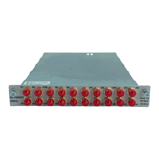
– The 34941A — the 50-Ω version — uses SMA connectors. When installing SMA cables on the 34941A module, it is recommend that you tighten them to 0.8 - 1.1 Nm (7-10 in-lbs) of torque. SMA connectors are easily damaged, especially when tightening a CAUTION neighboring connector with a wrench. -
Page 11: Operating Considerations
With RF MUX switches, you cannot open switches programmatically. You can only close a channel. When you close one channel, another channel automatically opens. Therefore, only one channel relay in each bank is closed at any time. Keysight 34941A-34942A User’s Guide... - Page 12 When installing the plastic shoulder washers, use 7 in-lbs of torque. The 34941A and 34942A are shipped from the factory chassis-grounded with metal shoulder washers installed on all connectors in each bank of relays.
-
Page 13: 34941A And 34942A Scpi Programming Examples
34941A and 34942A SCPI Programming Examples The programming examples below provide you with SCPI command examples to use for actions specific to the RF MUX switch modules. The slot and channel addressing scheme used in these examples follow the form sccc where s is the mainframe slot number (1 through 8) and ccc is the channel number. - Page 14 Note that clearing the cycle count on a specific channel will clear the count on all three relays in the corresponding bank. DIAGnostic:RELay:CYCLes:CLEar (@1103,1201) Example: Resetting module to power-on state The following command resets a module in slot 4 to its power-on state. SYSTem:CPON 4 Keysight 34941A-34942A User’s Guide...
-
Page 15: 34941A And 34942A Simplified Schematic
34941A and 34942A Simplified Schematic Both the 34941A and 34942A modules are configured alike. Each contains four banks of latching switches. Each bank consists of three Form C relays. The front panel of the two RF MUX modules are similar with channel labels in the same positions, the unique product number on the left, and the product description on the right. - Page 16 Index channel relays connectors description electrical isolation grounding mini SMB connectors module descriptions module impedance 34941A 34942A programming examples relay operation safety notices simplified schematics SMA connectors Keysight 34941A-34942A User’s Guide...
- Page 17 THIS PAGE HAS BEEN INTENTIONALLY LEFT BLANK. Keysight 34941A-34942A User’s Guide...
- Page 18 This information is subject to change without notice. Always refer to the Keysight website for the latest revision. © Keysight Technologies 2008-2019 Edition 3, July 2019 Printed in Malaysia *34980-90041* 34980-90041 www.keysight.com...
Need help?
Do you have a question about the 34941A and is the answer not in the manual?
Questions and answers