
Related Manuals for Keysight Technologies M9195A PXIe


Summary of Contents for Keysight Technologies M9195A PXIe
- Page 1 Startup Guide For the User Guide, software and other important documentation, see the M9195A Software and Product Information CD. Keysight M9195A PXIe Digital Stimulus/Response with PPMU: 250 MHz, 16 channel...
-
Page 3: Declaration Of Conformity
(prod- license. sent from Keysight Technologies, Inc. as uct-specific information and support, governed by United States and interna- software and documentation updates) tional copyright laws. www.keysight.com/find/assist (world- U.S. -
Page 4: Safety Information
Safety Information Do Not Remove Instrument Cover The following general safety precau- tions must be observed during all Only qualified, service-trained person- phases of operation of this instrument. nel who are aware of the hazards Failure to comply with these precau- involved should remove instrument tions or with specific warnings or oper- covers. - Page 5 Safety Symbols ICES/NMB-001 ISM GRP 1-A A CAUTION denotes a hazard. It calls attention to an operating pro- Notice for European Community: This MSIP-REM-Kst cedure or practice, that, if not cor- product complies with the relevant -BLM9195A rectly performed or adhered to European legal Directives: EMC Direc- could result in damage to the South Korean Class A EMC Declara-...
-
Page 7: Table Of Contents
Contents M9195A PXIe Digital Stimulus/Response At a Glance....9 M9195A key features ......... . . 9 Follow the Startup Sequence . - Page 8 Keysight M9195A PXIe Digital Stimulus/Response Module Startup Guide...
-
Page 9: M9195A Pxie Digital Stimulus/Response At A Glance
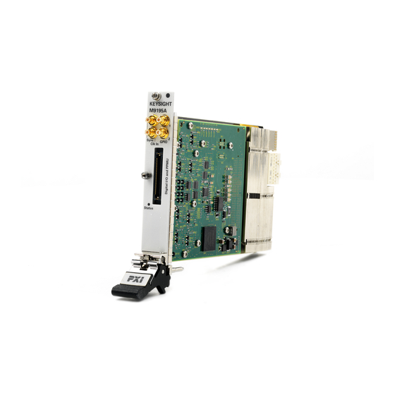
Startup Guide M9195A PXIe Digital Stimulus/Response At a Glance The M9195A PXIe Digital Stimulus/Response (DSR) module is a single slot, 250 MHz Digital Stimulus/Response (DSR) PXI Express (PXIe) module, providing 16 bidirectional I/O channels; Per-pin Parametric Measurement Unit (PPMU); four high voltage lines useful for flash programming;... -
Page 10: Follow The Startup Sequence
1. Unpack & Inspect 2. Verify Shipment 3. Install Software BOX CONTENT LIST IO Libraries Suite Module software 4. Install Module and drivers Power p/n: 5972-3335 S eptember 2014 Keysight M9195A PXIe Digital Stimulus/Response Startup Guide... -
Page 11: Related Documentation
Specifications published in the data sheet only apply to the current manufacturing version of the module. - Security Guide: Details the internal memory locations of the M9195A PXIe Digital Stimulus/Response module. It describes instrument security features and the steps necessary to declassify the products through memory sanitization or removal. -
Page 12: Step 1: Unpack And Inspect The Module
(see warranty information at beginning of this document). To avoid damage when handling a module, do not touch exposed connector pins. Keysight M9195A PXIe Digital Stimulus/Response Startup Guide... -
Page 13: Returning A Module For Service
“FRAGILE”. On the shipping label, write ATTENTION REPAIR DEPARTMENT and the RMA number. If any correspondence is required, refer to the product by both serial number and model number. Keysight M9195A PXIe Digital Stimulus/Response Startup Guide... -
Page 14: Step 2: Verify M9195A Shipment Contents
Memory, 125 Mb/Channel M9195A-S04 Multi-site configuration M9195A-SR2 Maximum clock rate, 250 MHz M9195A accessories The following table lists the accessories available for the M9195A PXIe Digital Stimulus Response module. Accessory Number Option Description Y1245A Single-site Digital Stimulus/Response Cable: 0.5m Y1246A... -
Page 15: Step 3: Install The Software
• Keysight M9048A PCIe Desktop Adapter x8, with cable (for desktop PCs) or an equivalent remote controller using a PC running an operating Introduction to KtMDsr systems listed in the file (see above). Keysight M9195A PXIe Digital Stimulus/Response Startup Guide... -
Page 16: Power Up The Controller
Start > Keysight Instrument Drivers > IVI-COM-C Drivers > KtMDsr Digital Stimulus Response > ___Introduction to KtMDsr vM.m.b.r-A___.htm - M9195A instrument software, which includes the Soft Front Panel (SFP), device drivers (IVI-C and IVI-COM), and documentation for the M9195A PXIe Digital Stimulus/Response module. This software is available at www.keysight.com/find/M9195A. -
Page 17: Software Installation Procedure
Keysight IO Libraries Suite is required to run the DSR driver software, including the DSR Soft Front Panel. Install the M9195A product software: Using the Keysight M9195A PXIe Digital Stimulus/Response Software and Product Information CD (M9195-10002), launch the installer. When the Install Wizard starts, click the Next button. -
Page 18: Step 4: Install The Module
When powering-up the PXI chassis and during the first DSR driver initialization after power-up (from the IVI API or from the M9195A Soft Front Panel) make certain that no device–under–test (DUT) is connected to the M9195A module. Keysight M9195A PXIe Digital Stimulus/Response Startup Guide... -
Page 19: Module Installation Procedure
Secure the front panel to the chassis using the two module front-panel mounting screws. Performance may suffer if the screws are not tightened properly. Verify that the PXI chassis fans are operable and free of dust and other contaminants that may restrict airflow. Keysight M9195A PXIe Digital Stimulus/Response Startup Guide... - Page 20 Cable Interface. Power up the PXI chassis. Reboot the PC host. Proceed to Step 5: Verify Operation of the Keysight M9195A PXIe Digital Stimulus/Response module (“Step 5: Verify Operation of the M9195A Module” on page 21).
-
Page 21: Step 5: Verify Operation Of The M9195A Module
Step 5: Verify Operation of the M9195A Module Step 5: Verify Operation of the M9195A Module In this step you will verify correct operation of the Keysight M9195A PXIe Digital Stimulus/Response module. Before running Self Test or Automatic Corrections, ensure that all required software is installed, the chassis is powered on, and all front panel cabling is removed. -
Page 22: Conduct A Self Test
To start the Self Test, click Utilities > Sel f Test... and the Run Sel f Test... button. Follow all screen prompts. Click Yes when all cables have been removed. Figure 2 Initiate the M9195A Self Test Keysight M9195A PXIe Digital Stimulus/Response Startup Guide... - Page 23 24. Any failures are noted in the display. Figure 3 Self Test Completed If either Self Test or Automatic Corrections fail (see next page), refer to “M9195A Module Level Troubleshooting” on page 34 to understand the source of the failure. Keysight M9195A PXIe Digital Stimulus/Response Startup Guide...
-
Page 24: Step 6: Execute Automatic Corrections
The module calibration may be performed by the service center or by self-maintainers with the optional Keysight Y1252A Calibration Kit. Refer to the M9195A Service Guide and the Soft Front Panel Help for more detailed information. Keysight M9195A PXIe Digital Stimulus/Response Startup Guide... - Page 25 21), connect to the M9195A module for which you want to execute Automatic Corrections. Select the Instrument tab in the Soft Front Panel as in Figure Figure 4 M9195A PXIe DSR: Instrument tab Keysight M9195A PXIe Digital Stimulus/Response Startup Guide...
- Page 26 – Use Window50Hz if you notice power line noise and your local power is 50 – Use Window60Hz if you notice power line noise and your local power is 60 Now, to run Automatic Corrections, Click the Execute Automatic Corrections... button in Figure Keysight M9195A PXIe Digital Stimulus/Response Startup Guide...
- Page 27 After you update the status, the status should be False. Proceed to “A Quick-Start for Programming the DSR” on page 28. It may take several minutes for Automatic Corrections to complete. When finished, the M9195A is left in its power-on, reset state. Keysight M9195A PXIe Digital Stimulus/Response Startup Guide...
-
Page 28: A Quick-Start For Programming The Dsr
IntelliSense prompts for easy access as you code. – You can also access the Help file directly from the Start menu: Start > All Programs > Keysight Instrument Drivers > IVI-COM-C Drivers > KtMDsr Digital Stimulus Response > KtMDsr Documentation. Keysight M9195A PXIe Digital Stimulus/Response Startup Guide... -
Page 29: Programming Model
You can also use the M9195A Soft Front Panel (SFP) to learn to use the module. Refer to the User Guide for the chapter on “Using STIL”. Keysight M9195A PXIe Digital Stimulus/Response Startup Guide... -
Page 30: The Dsr Help File: Your Best Programming Resource
Read the overview of the STIL Components. This overview is found in the STIL API Components article in the Help file: General KtMDsr Usage Information > Dynamic Repeated Capabilities > STIL API Components. The overview covers DCLevels, MacroDefs, PatternBurst, PatternExec, Pattern, SignalGroups, Signals, Sites, and WaveformTables. Keysight M9195A PXIe Digital Stimulus/Response Startup Guide... - Page 31 9, this time focusing on the methods and properties. While reading about each method or property, keep in mind the section (hierarchy) where it is located, as this will provide useful context. Keysight M9195A PXIe Digital Stimulus/Response Startup Guide...
-
Page 32: M9195A Front Panel Features
*The GPIO1, GPIO2 and Sync Input SMB connectors are reserved for future use; they are not activated on the module. **The CLK In SMB connector allows you to input a 10 MHz or 100 MHz reference clock. Keysight M9195A PXIe Digital Stimulus/Response Startup Guide... -
Page 33: M9195A Block Diagram
M9195A Block Diagram M9195A Block Diagram The following diagram shows a simplified block diagram of the M9195A module. Keysight M9195A PXIe Digital Stimulus/Response Startup Guide... -
Page 34: M9195A Specifications
Once you open the M9195A SFP, select the module, and then Connect. The module initializes. If no modules are visible in the SFP “Connect to Instrument” dialog, verify that the module has been properly installed in the chassis. Perform a module-level troubleshooting check. Keysight M9195A PXIe Digital Stimulus/Response Startup Guide... -
Page 35: Status Led
M9195A Module Level Troubleshooting Status LED When power is first applied to the M9195A PXIe DSR, the LED starts in the Off state, and then changes to green after a few moments when PXI enumeration has taken place. In general, when the Status LED is solid green the module is working correctly. - Page 36 M9195A Module Level Troubleshooting Keysight M9195A PXIe Digital Stimulus/Response Startup Guide...
- Page 38 This information is subject to change without notice. © Keysight Technologies 2013 - 2015 Published in USA, December 2015 *M9195-90001* M9195-90001 www.keysight.com...
Need help?
Do you have a question about the M9195A PXIe and is the answer not in the manual?
Questions and answers