
Subscribe to Our Youtube Channel
Related Manuals for Keysight Technologies M8192A


Summary of Contents for Keysight Technologies M8192A
- Page 1 Test Equipment Depot - 800.517.8431 - 99 Washington Street Melrose, MA 02176 - TestEquipmentDepot.com Keysight M8192A Synchronization module for M8190A User’s Guide...
- Page 3 Software is delivered and licensed as “Commercial computer software” as There is a risk of instrument defined in DFAR 252.227-7014 (June © Keysight Technologies, Inc. 2014 malfunction when touching a 1995), or as a “commercial item” as connector. No part of this manual may be defined in FAR 2.101(a) or as...
- Page 4 Safety Summary General Safety The following general safety precautions must be observed during all phases of operation of this instrument. Failure to comply with these precautions or with Precautions specific warnings elsewhere in this manual violates safety standards of design, manufacture, and intended use of the instrument.
- Page 5 Safety Symbols Table 1 Safety Symbol Symbol Description Indicates warning or caution. If you see this symbol on a product, you must refer to the manuals for specific Warning or Caution information to avoid personal injury or damage to the product. C-Tick Conformity Mark of the Australian ACA for EMC compliance.
-
Page 7: Table Of Contents
3.6.1 Requirements for Controlling the Synchronous System 3.6.2 Synchronous System Operation Modes 3.6.3 Control Parameters M8192A Soft Front Panel 4.1 Introduction 4.2 Launching the M8192A Soft Front Panel 4.3 M8192A Soft Front Panel 4.3.1 Title Bar Keysight M8192A User’s Guide... - Page 8 5.5.10 *STB? 5.5.11 *TST? 5.5.12 *LRN? 5.5.13 *WAI 5.6 Status Model 5.6.1 :STATus:PRESet 5.6.2 Status Byte Register 5.6.3 Questionable Data Register Command Subsystem 5.6.4 Operation Status Subsystem 5.6.5 Run Status Subsystem 5.7 :ARM/TRIGger Subsystem 5.7.1 :ABORt Keysight M8192A User’s Guide...
- Page 9 :MMEMory:RDIRectory <directory_name> 5.9.10 :MMEMory:LOAD:CSTate <file_name> 5.9.11 :MMEMory:STORe:CSTate <file_name> 5.10 TEST Subsystem 5.10.1 :TEST:PON? 5.10.2 :TEST:TST? Characteristics 6.1 Performance Specification 6.2 General 6.3 Maintenance 6.3.1 ESD Protection 6.3.2 Power and Ventilation Requirements 6.3.3 Thermal Protection 6.3.4 Cleaning Recommendation Keysight M8192A User’s Guide...
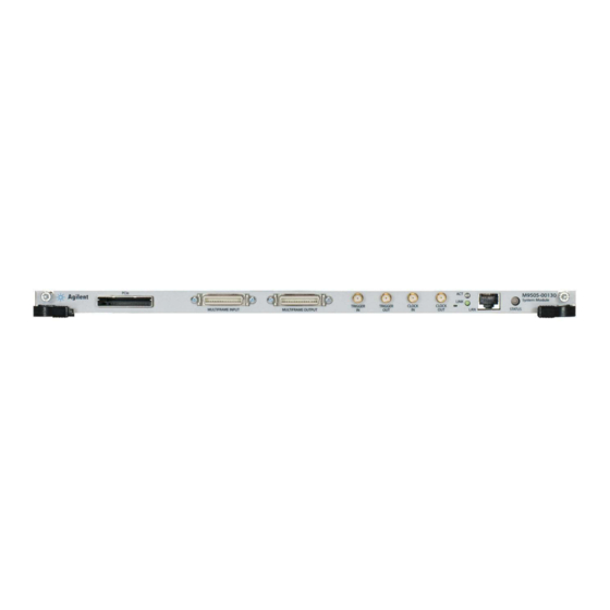
- Page 11 Keysight M8192A - Synchronization module for M8190A User’s Guide Introduction 1.1 Document History / 13 1.2 Accessories / 14 1.3 M8192A Front Panel / 14 M8192A User’s Guide...
- Page 12 SYNC CLK output. The M8192A module has its own Soft Front Panel but no extra firmware like the M8190A which allows you to control the trigger mode, trigger level and common start/stop of the multi-module setup.
-
Page 13: Introduction
Introduction Features and Benefits M8192A provides following features and benefits: Synchronization of up to 6 M8190A modules (= 12 channels) One trigger input can trigger up to 6 M8190A modules with deterministic latency Skew repeatability of 2 ps between any two channels – independent of sample rate ... -
Page 14: Accessories
Introduction 1.2 Accessories The M8192A is delivered with three clock cables and two trigger cables to build a 4- channel synchronous system using two M8190A. In order to synchronize more than two M8190A, additional clock and trigger cables must be ordered, as listed in the following table. - Page 15 Connect to TRIGGER IN of M8190A master module and M8190A slave module Status LED Two LEDs are available at the front panel to indicate the status of the M8192A module: The green “Access”LED indicates that the controlling PC exchanges data with the M8192A module.
-
Page 17: M8192A Installation
Keysight M8192A - Synchronization module for M8190A User’s Guide M8192A Installation 2.1 Introduction / 18 2.2 AXI Chasis / 26 M8192A User’s Guide... -
Page 18: Introduction
M8192A Installation 2.1 Introduction This chapter explains the steps required to install M8192A module. 2.1.1 Pre-Requisites The following are the pre-requisites for installing Keysight M8192A software: The supported operating systems are: Windows Vista (32 bit) Windows Vista (64 bit) ... -
Page 19: Installation Process
M8192A Installation 2.1.2 Installation Process Follow the given steps to install M8192A module on your system: Double-click the executable (M8192_Setup.exe). This executable file will be available on either CD or Web. The Keysight M8192A Setup will prepare the InstallShield Wizard for the installation process. - Page 20 M8192A Installation Follow the onscreen instructions to begin the installation process. Click Next. We recommend you to read the document to check if your hardware configuration is supported. Click Next to proceed to the license agreements. Keysight M8192A User’s Guide...
- Page 21 M8192A Installation Accept the terms of Keysight software end-user license agreement. Click Next. Accept the terms of Keysight IVI Driver Source Code license agreement. Click Next. Keysight M8192A User’s Guide...
- Page 22 M8192A Installation Select Yes if you want to read the post-installation instructions, once the installation is finished. Click Next. Select a setup type either Complete or Custom. Click Next. Keysight M8192A User’s Guide...
- Page 23 M8192A Installation Click Next to begin installation. 10. The Keysight M8192A will configure the new software installation. Keysight M8192A User’s Guide...
- Page 24 M8192A Installation 11. The following screen will appear once the Keysight M8192A software is successfully installed on your system. Click Finish to restart your system. This completes the Keysight M8192A software installation. Keysight M8192A User’s Guide...
-
Page 25: Post Installation Steps
Follow the post installation steps as shown below: Shut down PC and instrument. Connect instrument to PC using the PCIe cable. Switch on instrument. Wait until the “Access” LED of the M8192A has switched from red to green. Switch on PC. -
Page 26: How To Control The Instrument
Add Keysight M8190 instruments to the system and connect them to the M8192. Use Help > About to get information about available remote connections. 2.2 AXI Chasis 2.2.1 ESM Front Panel Connector The ESM Front Panel Connector is shown in the figure below: Keysight M8192A User’s Guide... - Page 27 M8192A synchronization module is needed instead. Trigger In External Trigger connections. The Trigger In of the AXIe ESM cannot be used to trigger the M8192A. Trigger Out The M8192A has its own Trigger In. The Trigger Out of the AXIe ESM cannot be controlled by the M8192A.
-
Page 29: System Configuration
Keysight M8192A - Synchronization module for M8190A User’s Guide System Configuration 3.1 Introduction / 30 3.2 Supported AXIe Frame Combinations / 31 3.3 Controlling One AXIe Chassis / 33 3.4 Controlling Multiple AXIe Chassis / 35 3.5 Synchronous System Cabling / 38 3.6 Controlling the Synchronous System... -
Page 30: Introduction
The M8192A synchronization module is designed to synchronize up to six M8190A arbitrary waveform generator modules. The M8190A modules can be located in the same or different AXIe chassis as the M8192A. This allows very flexible configurations to address a variety of applications. -
Page 31: Or 8) M8190A Arbitrary Waveform Generator Channels
3.1.2 6 (or 8) M8190A Arbitrary Waveform Generator Channels To configure a synchronous system with 6 (or 8) channels, use two 5-slot AXIe chassis, one M8192A and 3 (or 4) M8190A 2-channel Arbitrary Waveform Generator modules. This synchronous system can be controlled from one external PC that supports two PCIe adapter cards. - Page 32 Two M9505A 5-slot AXIe chassis plus one M9502A 2-slot AXIe chassis Seven M9502A 2-slot AXIe chassis or One M9505A 5-slot AXIe chassis plus four M9502A 2-slot AXIe chassis or Two M9505A 5-slot AXIe chassis plus two M9502A 2-slot AXIe chassis or Three M9505A 5-slot AXIe chassis Keysight M8192A User’s Guide...
-
Page 33: Controlling One Axie Chassis
A synchronous system with four synchronous M8190A AWG channels consists of: Two M8190A 2-channel arbitrary waveform generator modules M8192A synchronization module. The delivery content of the M8192A synchronization module includes: Three clock cables with proprietary multi-coax connectors at each side. - Page 34 System Configuration Figure 4 M8192A-802 QMA to SMA trigger cable Keysight M8192A User’s Guide...
-
Page 35: Controlling Multiple Axie Chassis
If you have two or more AXIe chassis, the solution is to connect them to an optional switch or hub as shown in Figure 6. In this scenario, the Host PC must connect to the same network hub or switch as the AXIe chassis. Keysight M8192A User’s Guide... - Page 36 Using a LAN switch for multiple AXIe chassis Although it is not required, manually assigned a unique, static IP address in the optional switch, will speed up network resolution at Windows startup and eliminate any potential network resolution issues. Keysight M8192A User’s Guide...
-
Page 37: Multiple Pc Controls Multiple Chassis
If you have multiple PCs that are connected to multiple AXIe chassis, each PC controls one AXIe chassis over PCIe using an M9048A PCIe IF card. The “Master” PC that controls the M8192A over PCIe, controls the “Slave” PCs using the LAN IF card. -
Page 38: Synchronous System Cabling
An eight channel synchronous system consists of: Four M8190A 2-channel arbitrary waveform generator modules M8192A synchronization module. The delivery content of the M8192A synchronization module includes: Five clock cables with proprietary multi-coax connectors at each side. -
Page 39: Controlling The Synchronous System
SYS CLK outputs of the M8192A must be used in ascending order without leaving a gap. Example: For four M8190A, SYSCLK OUT 1, SYSCLK OUT 2, SYSCLK OUT 3 and SYSCLK OUT 4 must be connected. - Page 40 Verify that the firmware version of all M8190A AWG modules and the M8192A synchronization module of the synchronous system is identical and higher than V3.0.0 Verify that each M8190A of the synchronous system has a common set of options.
-
Page 41: Control Parameters
3.6.3.1 Using M8192A Soft Front Panel The Soft Front Panel of the M8192A lists all M8190A that are available in the local PC or in ACE in a table. Using this table the user can define that a certain M8190A will ... - Page 42 System Configuration Table 7 Parameters controlled from M8192A and M8190A Functionality M8192A Synchronization Module M8190A Master Module M8190A Slave Module Sample frequency Not available Controls all M8190A. Modification is Disabled only possible in configuration mode Output Mode :14 bit or 12 bit Not available Controls all M8190A.
-
Page 43: M8192A Soft Front Panel
Keysight M8192A - Synchronization module for M8190A User’s Guide M8192A Soft Front Panel 4.1 Introduction / 44 4.2 Launching the M8192A Soft Front Panel / 44 4.3 M8192A Soft Front Panel / 46 4.4 Driver Call Log Window / 51 4.5 Errors Window... -
Page 44: Introduction
M8192A Soft Front Panel 4.1 Introduction This chapter describes the M8192A Soft Front Panel (SFP). 4.2 Launching the M8192A Soft Front Panel There are three ways to launch the M8190A Soft Front Panel. They are as following: From the Start Menu, select All Programs Keysight M8192 M8192 Soft Front Panel. - Page 45 M8192A Soft Front Panel The following screen will appear: Figure 9 M8192A connected to PC Keysight M8192A User’s Guide...
-
Page 46: M8192A Soft Front Panel
The instrument selection dialog shows the addresses of the discovered M8192A modules. Select a module from the list and press “Connect”. If no M8192A module is connected to your PC, you can check “Simulation Mode” to simulate an M8192A module. -
Page 47: Title Bar
M8192A Soft Front Panel 4.3.1 Title Bar The title bar contains the standard Microsoft Windows elements such as the window title and the icons for minimizing, maximizing, or closing the window. 4.3.2 Menu Bar The menu bar consists of various pull down menus that provide access to the different functions and launch interactive GUI tools. - Page 48 M8192A Soft Front Panel 4.3.2.2 View The View menu includes the following selections: View Refresh Reads the instrument state and updates all fields. 4.3.2.3 Utilities The Utility menu includes the following selections: Utility Reset Resets the instrument, reads the state and updates all fields.
-
Page 49: Status Bar
Click this field to open the “Error” window. 4.3.4 Tabs (Module/Sync Tabs) These tabs are used to configure the most important parameters of the M8192A module. They are described in detail in the sections that follow. 4.3.5 Numeric Control Usage The numeric control is used to adjust the value and units. - Page 50 M8192A Soft Front Panel Figure 11 Tooltip showing possible values in the range The numeric controls can be used in the following ways: Use the up/down arrows to change the value. The control automatically stops at the maximum/minimum allowed value.
-
Page 51: Driver Call Log Window
M8192A Soft Front Panel 4.4 Driver Call Log Window Use this window to inspect the sequence of SCPI commands used to configure the M8192A module. Figure 13 Driver Call Log Window It has the following buttons: Save… Saves the Driver Call Log as a text file. -
Page 52: Errors Window
M8192A Soft Front Panel 4.5 Errors Window Use this window to read out and display the error queue of the M8192A module. Figure 14 Driver Call Log Window It has the following buttons: Get Instrument Errors Queries the instruments error queue and displays the errors, if any. -
Page 53: Module Tab
M8192A Soft Front Panel 4.6 Module Tab The module panel allows you to discover available M8190A modules and to define a multi-module group consisting of one master and up to five slave modules. The VISA resource strings for available M8190A modules are displayed in a list under column “VISA Resource”. - Page 54 M8192A Soft Front Panel It has the following controls: Discover: Click this button to find the available M8190A modules. The modules that are found are displayed in the list. The firmware of the modules to be discovered must be running and the modules must be entered into the Keysight Connection Expert.
-
Page 55: Sync Tab
M8192A Soft Front Panel 4.7 Sync Tab The Sync tab allows you to modify parameters that affect all the modules in the synchronous system. This tab can be used to: Configure the M8192 trigger input Set trigger threshold and impedance ... - Page 56 Threshold: Use the numeric control to enter the threshold level of the M8192A trigger input. Impedance: Use this dropdown list to set the impedance of the M8192A trigger input. Arm: Press this button to set all channels of the multi-module group to an armed state.
-
Page 57: Remote Programming
Keysight M8192A - Synchronization module for M8190A User’s Guide Remote Programming 5.1 Introduction / 58 5.2 SCPI Programming / 58 5.3 Programming Recommendations / 61 5.4 System Related Commands (SYSTem Subsystem) / 62 5.5 Common Command List / 66 5.6 Status Model / 68 5.7 :ARM/TRIGger Subsystem... -
Page 58: Introduction
This can be done in the Windows Start menu (Keysight M8192 M8192 Soft Front Panel). You can open the “About” dialog from the M8192A Soft Front Panel to see the VISA Resource String for the different connection types. - Page 59 SCPI commands. (Refer to the table above.) /Socket, /Telnet, /Inst: If -1, don’t start the respective servers Defaults: Socket port: 5025 (e.g. TCPIP0::localhost::5025::SOCKET) Telnet port: 5024 HiSLIP, VXI-11.3: 0 (e.g. TCPIP0::localhost::hislip0::INSTR, TCPIP0::localhost::inst0::INSTR) Keysight M8192A User’s Guide...
- Page 60 /NoAutoID : Do not automatically select ports and number for the connections, use the values specified with /Socket, /Telnet, /Inst or their respective default values instead. If both /NoAutoID and /AutoID are specified, /AutoID overrides /NoAutoID. Keysight M8192A User’s Guide...
-
Page 61: Programming Recommendations
) as the last command. This way intermediate stop/restarts are avoided and optimum execution performance is achieved. # set default settings # other commands to set modes # and parameters # set trigger impedance to High # start data generation. Keysight M8192A User’s Guide... -
Page 62: System Related Commands (System Subsystem)
The <SCPI program mnemonic> contains the node in standard SCPI format. The short form uses uppercase characters while the additional characters for the long form are in lowercase characters. Default nodes are surrounded by square brackets ([]). Keysight M8192A User’s Guide... -
Page 63: System:license:extended:list
:SYST:SET <binary block data> Query :SYST:SET? 5.4.5 :SYSTem:VERSion? Command :SYST:VERS? Long :SYSTem:VERSion? Parameters None Parameter Suffix None Description This query returns a formatted numeric value corresponding to the SCPI version number for which the instrument complies, for example “1999.0”. Keysight M8192A User’s Guide... -
Page 64: System:communicate
This query returns the VXI-11 instrument number used by the firmware. Example Query :SYST:COMM:INST? 5.4.6.2 :SYSTem:COMMunicate:HISLip[:NUMBer]? Command :SYST:COMM:HISL? Long :SYSTem:COMMunicate:HISLip? Parameters None Parameter Suffix None Description This query returns the HiSLIP number used by the firmware. Example Query :SYST:COMM:HISL? Keysight M8192A User’s Guide... - Page 65 This query returns the socket port used by the firmware. Example Query :SYST:COMM:SOCK? 5.4.6.4 :SYSTem:COMMunicate:TELNet[:PORT]? Command :SYST:COMM:TELN? Long :SYSTem:COMMunicate:TELNet? Parameters None Parameter Suffix None Description This query returns the telnet port used by the firmware. Example Query :SYST:COMM:TELN? Keysight M8192A User’s Guide...
-
Page 66: Common Command List
Keysight Technologies, M8192A,<serial number>, x.x.x.x-h x.x.x.x= Firmware revision number, e.g. 2.0.0.0 h= Hardware revision number 5.5.2... -
Page 67: Rst
For proper operation, do not modify the returned string before sending it to the instrument. Use to send the learn string. See section 5.4.4. 5.5.13 *WAI Prevents the instrument from executing any further commands until the current command has finished executing. Keysight M8192A User’s Guide... -
Page 68: Status Model
5.6 Status Model Introduction This section describes the structure of the SCPI status system used by the M8192A. The status system records various conditions and states of the instrument in several register groups as shown on the following pages. Each of the register groups is made up of several low level registers called Condition registers, Event registers, and Enable registers which control the action of specific bits within the register group. - Page 69 Remote Programming Figure 17 Status Register Structure Keysight M8192A User’s Guide...
-
Page 70: Status:preset
One or more bits are set in the Standard Event Register Master Summary One or more bits are set in the Status Byte Register Operational Data One or more bits set in the Operation Data Register (bits must be enabled) Keysight M8192A User’s Guide... -
Page 71: Questionable Data Register Command Subsystem
Returns “0” Not used Returns “0” Not used 1024 Returns “0” Not used 2048 Returns “0” Not used 4096 Returns “0” Not used 8192 Returns “0” Not used 16384 Returns “0” Not used 32768 Returns “0” Keysight M8192A User’s Guide... - Page 72 Setting both positive/negative filters true allows an event to be reported anytime the condition changes. Clearing both filters disable event reporting. The contents of transition filters are unchanged by Keysight M8192A User’s Guide...
-
Page 73: Operation Status Subsystem
A query of the register returns a decimal value which corresponds to the binary-weighted sum of all bits set in the register. Keysight M8192A User’s Guide... - Page 74 Setting both positive/negative filters true allows an event to be reported anytime the condition changes. Clearing both filters disable event reporting. The contents of transition filters are unchanged by Keysight M8192A User’s Guide...
-
Page 75: Run Status Subsystem
The following SCPI commands and queries are supported: :STATus:OPERation:RUN[:EVENt]? :STATus:OPERation:RUN:CONDition? :STATus:OPERation:RUN:ENABle[?] :STATus:OPERation:RUN:NTRansition[?] :STATus:OPERation:RUN:PTRansition[?] Table 12 Run Status Register Bit Number Decimal Value Definition Run Status Indicates if the multi-module group is in running/armed state (:INIT:IMM was executed). Keysight M8192A User’s Guide... -
Page 76: Arm/Trigger Subsystem
Command :ARM[:SEQ][:STAR][:LAY]:TRIG:LEV[?] Long :ARM[:SEQuence][:STARt][:LAYer]:TRIGger:LEVel[?] Parameters <level>|MINimum|MAXimum Parameter Suffix Volt (V) or millivolt (mV) Description Set or query the threshold level of the M8192A trigger input. <level> – Threshold level voltage. Example Command :ARM:TRIG:LEV 3e-9 Query :ARM:TRIG:LEV? Keysight M8192A User’s Guide... -
Page 77: Arm[:Sequence][:Start][:Layer]:Trigger:impedance[?] Low|High
Parameter Suffix None Description Set or query the M8192A’s hardware input disable state for the trigger function. When the hardware input is disabled, a trigger can only be generated using the :TRIGger[:SEQuence][:STARt]:BEGin[:IMMediate] command. When the hardware input is enabled, a trigger can be generated by command or by a signal present at the trigger input of the M8192A. -
Page 78: Instrument Subsystem
Remote Programming 5.8 INSTrument Subsystem 5.8.1 :INSTrument:SLOT[:NUMBer]? Command :INST:SLOT[:NUMB]? Long :INSTrument:SLOT[:NUMBer]? Parameters None Parameter Suffix None Description Query the instrument’s slot number in its AXIe frame. Example Query :INST:SLOT? Keysight M8192A User’s Guide... -
Page 79: Multi-Module Configuration Commands
5.8.2.3 :INSTrument: SLAVe:LIST? Command :INST:SLAV:LIST? Long :INSTrument:SLAVe:LIST? Parameters None Parameter Suffix None Description This query returns a comma-separated list of VISA resource strings of all M8190A slave modules that belong to the multi-module group. Example Query :INST:SLAV:LIST? Keysight M8192A User’s Guide... - Page 80 5.8.2.6 :INSTrument: SLAVe:DELete < visa_resource_string> Command :INST:SLAV:DEL Long :INSTrument:SLAVe:DELete Parameters < visa_resource_string> Parameter Suffix None Description This command deletes the M8190A slave module with the passed VISA resource string from the multi-module group. Example Command :INST:SLAV:DEL “TCPIP0::localhost::hislip0::INSTR” Keysight M8192A User’s Guide...
-
Page 81: Mmemory Subsystem
MMEM commands requiring <directory_name> assume the current directory if a relative path or no path is provided. If an absolute path is provided, then it is ignored. 5.9.1 :MMEMory:CATalog? [<directory_name>] Command :MMEM:CAT? Long :MMEMory:CATalog? Parameters None Parameter Suffix None Keysight M8192A User’s Guide... -
Page 82: Mmemory:cdirectory [
, this value is set to the default user data storage area, that is defined as System.Environment.SpecialFolder.Personal e.g. C:\Users\Name\Documents — Query returns full path of the default directory. Example Command :MMEM:CDIR “C:\Users\Name\Documents” Query :MMEM:CDIR? 5.9.3 :MMEMory:COPY <string>,<string>[,<string>,<string>] Command :MMEM:COPY Long :MMEMory:COPY Parameters <string>,<string> Parameter Suffix None Keysight M8192A User’s Guide...] -
Page 83: Mmemory:delete
Command :MMEM:DATA “C:\data.txt”, #14test 5.9.6 :MMEMory:DATA? <file_name> Command :MMEM:DATA? Long :MMEMory:DATA? Parameters <file_name> Parameter Suffix None Description The query form is > with the response being the associated <data> in block format. Example Query :MMEM:DATA? "C:\data.txt" Keysight M8192A User’s Guide...[, ] -
Page 84: Mmemory:mdirectory
:MMEMory:RDIRectory Parameters <directory_name > Parameter Suffix None Description Removes a directory. The <directory_name> parameter specifies the directory name to be removed. All files and directories under the specified directory are also removed. Example Command :MMEM:RDIR "C:\newdata_dir" Keysight M8192A User’s Guide... -
Page 85: Mmemory:load:cstate
Current STate of instrument is loaded from a file. Example Command :MMEM:LOAD:CST "C:\data.txt" 5.9.11 :MMEMory:STORe:CSTate <file_name> Command :MMEM:STOR:CST Long :MMEMory:STORe:CSTate Parameters <file_name > Parameter Suffix None Description Current STate of instrument is stored to a file. Example Command :MMEM:STOR:CST "C:\data.txt" Keysight M8192A User’s Guide... -
Page 86: Test Subsystem
Return the results of the power on self-tests. Example Query :TEST:PON? 5.10.2 :TEST:TST? Command :TEST:TST? Long :TEST:TST? Parameters None Parameter Suffix None Description Same as , but the actual test messages are returned. Example Query :TEST:TST? Currently same as Keysight M8192A User’s Guide... - Page 87 Keysight M8192A - Synchronization module for M8190A User’s Guide Characteristics 6.1 Performance Specification / 88 6.2 General / 88 6.3 Maintenance / 89 M8192A User’s Guide...
-
Page 88: Performance Specification
Warranty 3 years standard Cooling When operating the M8192A, choose a location that provides at least 80 mm of clearance at rear, and at Requirements least 30 mm of clearance at each side for the AXIe chassis. The instrument is not designed for outdoor use. Do not expose the instrument to rain or other excessive moisture. -
Page 89: Maintenance
Electrostatic discharge (ESD) can damage the circuits of the M8192A. Avoid applying CAUTION static discharges to the front-panel connectors. Before connecting any coaxial cable to the connectors, momentarily short the center and outer conductors of the cable together. -
Page 90: Power And Ventilation Requirements
6.3.4 Cleaning Recommendation To prevent electrical shock, disconnect the instrument from mains before cleaning. WARNING Use a dry cloth or one slightly dampened with water to clean external case parts. Do not attempt to clean internally. Keysight M8192A User’s Guide... - Page 92 This information is subject to change without notice. © Keysight Technologies 2014 Edition 4.0, November 2014...
Need help?
Do you have a question about the M8192A and is the answer not in the manual?
Questions and answers