Table of Contents
Advertisement
Quick Links
Download this manual
See also:
Service Manual
Advertisement
Table of Contents

Related Manuals for Keysight Technologies M937 A Series


Summary of Contents for Keysight Technologies M937 A Series
- Page 1 Keysight M937xA PXIe Vector Network Analyzer Modules M9370A, 300 kHz to 4 GHz M9371A, 300 kHz to 6.5 GHz M9372A, 300 kHz to 9 GHz M9373A, 300 kHz to 14 GHz M9374A, 300 kHz to 20 GHz M9375A, 300 kHz to 26.5 GHz Startup Guide...
- Page 2 Software is delivered and licensed as M9370-90001 “Commercial computer software” as © Keysight Technologies, Inc. 2014 defined in DFAR 252.227-7014 (June Print Date No part of this manual may be 1995), or as a “commercial item” as reproduced in any form or by any defined in FAR 2.101(a) or as...
-
Page 3: Table Of Contents
Contents ..........Getting Started Introduction Related Documentation STEP 1. - Page 4 Contents Before Applying Power Servicing Operating Conditions Regulatory Information Instructions for Use Safety Instrument Markings Declaration of Conformity Warranty...
-
Page 5: Getting Started
M937xA PXIe Vector Network Analyzer module. Additionally, installing the required software and verifying network analyzer module operation is documented. If you have any questions after reviewing this information, please contact your local Keysight Technologies Inc. representative or contact us through our support Website at http://na.support.keysight.com/pxi. -
Page 6: Step 1. Unpack And Inspect The Network Analyzer Modules
Getting Started STEP 1. Unpack and Inspect the Network Analyzer Modules STEP 1. Unpack and Inspect the Network Analyzer Modules The network analyzer modules are shipped in materials which prevent damage CAUTION from static. The modules should only be removed from the packaging in an anti-static area ensuring that correct anti-static precautions are taken. -
Page 7: Inspect For Damage
Getting Started STEP 1. Unpack and Inspect the Network Analyzer Modules Unpack the network analyzer modules from the shipping containers. Keep the black and red plastic port protectors and the shipping containers for possible reuse. Inspect for Damage After unpacking a network analyzer module, inspect it for any shipping damage. -
Page 8: Step 2. Check The Shipment
Getting Started STEP 2. Check the Shipment STEP 2. Check the Shipment Use the Contents List in the shipping container to verify the completeness of your shipment. If not complete, refer to “Contacting Keysight” on page... -
Page 9: Step 3. Install The Software
Getting Started STEP 3. Install the Software STEP 3. Install the Software System Requirements Topic Windows 7 and Vista Requirements Operating system Windows 7 (32 bit and 64 bit) Windows Vista, SP 1 and SP2 (32-bit and 64-bit) Processor speed 1.5 GHz dual core (x86 or x64) minimum... -
Page 10: Power Up The Controller
Getting Started STEP 3. Install the Software Power Up the Controller If you are using a remote controller, complete the following steps: 1. Install the cable interface between the remote controller and the chassis. If you are using an Keysight M9021A cable interface, refer to the Keysight M9021A documentation for further details. - Page 11 Getting Started STEP 3. Install the Software Software Installation Procedure 1. Install the Keysight IO Libraries Suite, using either the Keysight IO Libraries Suite CD included with your shipment (CD part number E2094-60003), or the downloadable file at www.keysight.com/find/iosuite. Follow the installer prompts to install the IO libraries.
-
Page 12: Step 4. Install The Network Analyzer Modules
Getting Started STEP 4. Install the Network Analyzer Modules STEP 4. Install the Network Analyzer Modules Please review all safety information located in Chapter 3 before proceeding with IMPORTANT installing and using the network analyzer module. These modules can be used in a chassis with a PXIe, or PXI-H chassis slots. NOTE Recommended Best Practices to Ensure Proper and Safe Module Operating Conditions... -
Page 13: Tools Required For The Installation Procedure
Getting Started STEP 4. Install the Network Analyzer Modules Tools Required for the Installation Procedure • Phillips #1 torque driver, set to 4 in-lbs (0.45 N.m) - not supplied. • Socket adapter (part number 5023-1450) - supplied. • Torque driver (for use with socket adapter), set to 8 in-lb (0.91 N.m) - not supplied. - Page 14 Getting Started STEP 4. Install the Network Analyzer Modules b. Hold down the silver locking tab while pushing down the injector/ejector handle to the unlatched (downward) position, and slide the module to the rear of the chassis. c. Slide the module completely into the chassis. When you begin to feel resistance, pull up on the injector/ejector handle to fully inject the module into the chassis.
- Page 15 Getting Started STEP 4. Install the Network Analyzer Modules Figure 1-4 Single M937xA Network Analyzer Module Configuration In the following instructions, eight network analyzer modules are configured. Use these NOTE instructions as a general guide if installing a different number of modules. 11.As seen in Figure 1-5 on page 16, each module is shipped with two 50 ohm...
- Page 16 Getting Started STEP 4. Install the Network Analyzer Modules Figure 1-5 50 Ohm Loads Installed on the Network Analyzer Modules Figure 1-6 Socket Adapter for 50 Ohm Loads (part number 5023-1450)
- Page 17 Getting Started STEP 4. Install the Network Analyzer Modules 12.Install a semi-rigid cable (M9370-20018), seen in Figure 1-7, between the Trig Out port and the Trig In port on each of the module pairs (1 & 2, 2 & 3, 3 &...
- Page 18 Getting Started STEP 4. Install the Network Analyzer Modules Figure 1-8 Cable Removal Tool (part number 5002-3361) 13.Install a semi-rigid cable (M9370-20006), seen in Figure 1-9, between the LO Out port and the LO In port on each of the module pairs (1 & 2, 2 & 3, 3 &...
- Page 19 Getting Started STEP 4. Install the Network Analyzer Modules 15.Install a semi-rigid cable (M9370-20019), seen in Figure 1-10, between the Ref Out port and the Ref In port on each of the module pairs (1 & 2, 2 & 3, 3 &...
-
Page 20: Front Panel Features
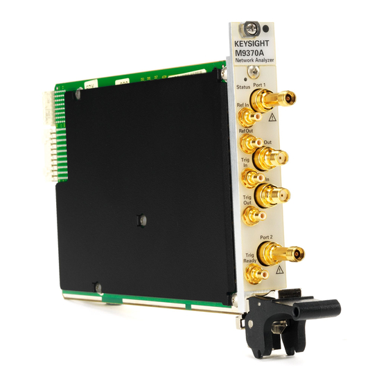
Getting Started STEP 4. Install the Network Analyzer Modules Front Panel Features Front Panel Photo Feature Description Status LED OFF: Power supply off. Safe to remove the network analyzer module from the chassis. AMBER: Power supply on, but no firmware is in control. GREEN: Firmware is in control;... -
Page 21: Step 5. Verify Operation Of The Network Analyzer Modules
Getting Started STEP 5. Verify Operation of the Network Analyzer Modules STEP 5. Verify Operation of the Network Analyzer Modules The Operator’s Check Allow the network analyzer modules to warm up for at least 15 minutes before performing NOTE the Operator’s Check. The operator’s check is a software driven test that checks the basic operation of the assemblies in all of the measurement port signal paths. -
Page 22: If The Operator's Check Fails
Getting Started STEP 5. Verify Operation of the Network Analyzer Modules Figure 1-11 Operator’s Check Dialog Box If the Operator’s Check Fails 1. Clean the test ports, and the open(s) or short(s). Torque to specification. Repeat the check. 2. If the check still fails, return the network analyzer module to Keysight. See “How to Return an Instrument for Service”... -
Page 23: Getting Help With Your Network Analyzer Module
Getting Help with Your Network Analyzer Module Help System M937xA PXIe Startup Guide Getting Help with Your Network Analyzer Module Help System Use the Help System to quickly reference programming and user documentation To access Help: • From the analyzer module software —... -
Page 24: N937Xa On The Internet
Getting Help with Your Network Analyzer Module N937xA on the Internet N937xA on the Internet The M937xA PXI Network Analyzer System Web page is another resource for help with the analyzer module. You can find all M937xA PXI network analyzer module documentation and other resources at: http://na.support.keysight.com/pxi/help. -
Page 25: Contacting Keysight
Getting Help with Your Network Analyzer Module Contacting Keysight Contacting Keysight Assistance with test and measurements needs and information on finding a local Keysight office are available on the Web at: www.keysight.com/find/assist. If you do not have access to the Internet, please contact your Keysight field engineer. - Page 26 Getting Help with Your Network Analyzer Module Contacting Keysight...
-
Page 27: Safety And Regulatory Information
Safety and Regulatory Information Maintenance M937xA PXIe Startup Guide Safety and Regulatory Information Maintenance To remove dirt or dust from the external case of the network analyzer module, clean the case using a dry or slightly-dampened cloth only. To prevent electrical shock, remove analyzer module from chassis slot for cleaning. Use a WARNING dry cloth or one slightly dampened with water to clean the external case parts. -
Page 28: Shipment For Service
Safety and Regulatory Information Shipment for Service Shipment for Service Contact Keysight Technologies for instructions on where to ship the analyzer module for service. “Contacting Keysight” on page Refer to Ship the analyzer module using the original packaging materials. Shipping the analyzer module in anything other than the original packaging may result in non-warranted damage. -
Page 29: Safety Symbols
Safety and Regulatory Information Safety Symbols Safety Symbols The following safety symbols are used throughout this manual. Familiarize yourself with each of the symbols and its meaning before operating this instrument. Denotes a hazard. It calls attention to a procedure that, if not correctly performed or CAUTION adhered to, would result in damage to or destruction of the product. -
Page 30: General Safety Considerations
Safety and Regulatory Information General Safety Considerations General Safety Considerations Before Applying Power If this product is not used as specified, the protection provided by the equipment could be WARNING impaired. This product must be used in a normal condition (in which all means for protection are intact) only. -
Page 31: Regulatory Information
Safety and Regulatory Information Regulatory Information Regulatory Information This section contains information that is required by various government regulatory agencies. Instructions for Use This product has been designed and tested in accordance with accepted industry standards, and has been supplied in a safe condition. The documentation contains information and warnings that must be followed by the user to ensure safe operation and to maintain the product in a safe condition. -
Page 32: Instrument Markings
Safety and Regulatory Information Regulatory Information Instrument Markings Some instrument markings may not appear on your analyzer. NOTE The instruction documentation symbol. The product is marked with this symbol when it is necessary for the user to refer to the instructions in the documentation. The AC symbol indicates the required nature of the line module input power. -
Page 33: Declaration Of Conformity
Safety and Regulatory Information Regulatory Information Declaration of Conformity A declaration of conformity is available upon request, or a copy is available on the Keysight Technologies Web site at http://www.keysight.com/go/conformity or by contacting Keysight - see “Contacting Keysight” on page... -
Page 34: Warranty
Keysight Technologies with the model and serial number of your instrument. Refer to “Contacting Keysight” on page Keysight Technologies does not warrant third-party system-level (combination of chassis, controllers, modules, etc.) performance, safety, or regulatory compliance, unless specifically stated.
Need help?
Do you have a question about the M937 A Series and is the answer not in the manual?
Questions and answers