Table of Contents
Advertisement
Quick Links
Advertisement
Table of Contents

Related Manuals for Keysight Technologies M8197A


Summary of Contents for Keysight Technologies M8197A
- Page 1 Keysight M8197A Synchronization module for M8195A User’s Guide...
-
Page 2: Safety Information
THER EXPRESS OR IMPLIED, WITH without prior agreement and written con- software under the same terms by which REGARD TO THIS MANUAL AND sent from Keysight Technologies, Inc. as the software is customarily provided to ANY INFORMATION CONTAINED governed by United States and interna- the public. - Page 3 Verify that all safety precautions are taken including those defined for the mainframe. Line Power The Keysight M8197A operates when installed in an Keysight AXIe mainframe. Requirements Do Not Operate in an Do not operate the instrument in the presence of flammable gases or fumes.
- Page 4 Safety Symbols Table 1 Safety Symbol Symbol Description Indicates warning or caution. If you see this symbol on a product, you must refer to the manuals for specific Warning or Caution information to avoid personal injury or damage to the product. C-Tick Conformity Mark of the Australian ACA for EMC compliance.
-
Page 5: Table Of Contents
3.5.1 Requirements for Controlling the Synchronous System 3.5.2 Synchronous System Operation Modes 36 3.5.3 Control Parameters M8197A Soft Front Panel Introduction Launching the M8197A Soft Front Panel M8197A Soft Front Panel 4.3.1 Title Bar 4.3.2 Menu Bar 4.3.3 Status Bar 4.3.4... - Page 6 5.5.13 *WAI Status Model 5.6.1 :STATus:PRESet 5.6.2 Status Byte Register 71 5.6.3 Questionable Data Register Command Subsystem 72 5.6.4 Operation Status Subsystem 5.6.5 Run Status Subsystem ARM/TRIGger Subsystem 5.7.1 :ABORt 5.7.2 :INITiate:CONTinuous:ENABle[?] SELF|ARMed 5.7.3 :INITiate:CONTinous[:STATe][?] OFF|ON|0|1 Keysight M8197A User’s Guide...
- Page 7 5.10.1 :MMEMory:CATalog? [<directory_name>] 89 5.10.2 MMEMory:CDIRectory [<directory_name>] 5.10.3 :MMEMory:COPY <string>,<string>[,<string>,<string>] 5.10.4 :MMEMory:DELete <file_name>[,<directory_name>] 5.10.5 :MMEMory:DATA <file_name>, <data> 5.10.6 :MMEMory:DATA? <file_name> 91 5.10.7 :MMEMory:MDIRectory <directory_name> 5.10.8 :MMEMory:MOVE <string>,<string>[,<string>,<string>] 5.10.9 :MMEMory:RDIRectory <directory_name> 5.10.10 :MMEMory:LOAD:CSTate <file_name> 5.10.11 :MMEMory:STORe:CSTate <file_name> 93 Keysight M8197A User’s Guide...
- Page 8 <frequency>|MINimum|MAXimum 5.14 STABle Subsystem 98 5.14.1 [:SOURce]:STABle:DYNamic:SELect <sequence_table_index> 5.15 TEST Subsystem 5.15.1 :TEST:PON? 98 5.15.2 :TEST:TST? 98 Characteristics Performance Specification General Maintenance 6.3.1 ESD Protection 6.3.2 Power and Ventilation Requirements 6.3.3 Thermal Protection 6.3.4 Cleaning Recommendation Keysight M8197A User’s Guide...
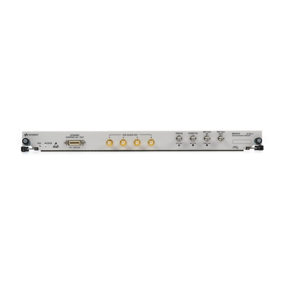
- Page 9 Keysight M8197A - Synchronization module for M8195A User’s Guide Introduction Document History Accessories M8197A Front Panel...
- Page 10 Introduction This chapter provides an overview of Keysight M8197A module. The M8197A synchronization module is used together with 1 to 4 M8195A modules to build a fully synchronous, phase coherent multi-channel generator system with up to 16 analog channels. When running in synchronous mode, all of the M8195A modules work with the same sample clock and start at the same time.
-
Page 11: Introduction 1
(Oct 2017) 1.2 Accessories The M8197A is always delivered with four Sys clock cables. The Sys Clock cables are matched pair cables. It is mandatory to use exactly the provided cables. Otherwise the synchronous system will not operate as specified. To avoid using non-specified cables, the Sys Clock cables are equipped with QMA to SMA connectors. -
Page 12: Front Panel Led
1.3.1 Front Panel LED 1.3.1.1 Status LED Two LEDs are available at the front panel to indicate the status of the M8197A module: “Access” LED indicates that the controlling PC exchanges data with the green M8197A module. - Page 13 The LED turns On red in case a set-up or a hold time violation has been detected. Note A ‘Force Trigger’ from the SFP or SCPI does not turn the LED ON Keysight M8197A User’s Guide...
- Page 14 Ref CLK In has been selected as the clock reference The externally applied clock signal is not valid. E.g. the frequency does not match the adjusted value or the amplitude is outside the specified range Keysight M8197A User’s Guide...
-
Page 15: M8197A Installation
Keysight M8197A - Synchronization module for M8195A User’s Guide M8197A Installation Introduction AXI Chasis... -
Page 16: Introduction
2 M8197A Installation 2.1 Introduction This chapter explains the steps required to install M8197A module. 2.1.1 Pre-Requisites The following are the pre-requisites for installing Keysight M8197A software: The supported operating systems are: Windows 10 (32 bit or 64 bit) ... -
Page 17: Installation Process
M8197A Installation 2 2.1.2 Installation Process Follow the given steps to install Keysight M8197A software on your system: Double-click the executable (M8197_Setup.exe). This executable file is available either on CD or Web. The Keysight M8197A Setup will prepare the InstallShield Wizard for the installation process. - Page 18 2 M8197A Installation Click Next. We recommend you to read the document to check if your hardware configuration is supported. Click Next to proceed to the license agreements. Keysight M8197A User’s Guide...
- Page 19 M8197A Installation 2 Accept the terms of ‘Keysight Software End-User License Agreement’. Click Next. Keysight M8197A User’s Guide...
- Page 20 2 M8197A Installation Accept the ‘Keysight IVI Driver Source Code License Agreement Terms’. Click Next. Keysight M8197A User’s Guide...
- Page 21 Select Yes if you want to read the post-installation instructions. Click Next to select setup type. 10. Select a setup type either Complete or Custom. If you select Custom, you can specify which optional features will be installed. Keysight M8197A User’s Guide...
- Page 22 2 M8197A Installation 11. Click Next. Keysight M8197A User’s Guide...
- Page 23 M8197A Installation 2 12. Click Install to begin the installation. The Setup Wizard will now install M8197A. Keysight M8197A User’s Guide...
- Page 24 2 M8197A Installation 13. The following screen will appear once the Keysight M8197A software is successfully installed on your system. 14. Click Finish to restart your system. This completes the Keysight M8197A software installation. Keysight M8197A User’s Guide...
-
Page 25: Post Installation Steps
M8197A Installation 2 2.1.3 Post Installation Steps If M8197A is already powered up and connected to PC using the PCIe, just reboot the PC, and start with step 5. No such reboot step is required in case of a USB connection. -
Page 26: How To Control The Instrument
2.1.4 How to Control the Instrument If you use a PCIe link to control the M8197A, the AXIe chassis must be switched-on before you start the PC. If you use a USB link to control the M8197A, it’s not mandatory that the AXIe chassis is powered and has booted prior to turning on the PC. - Page 27 Trigger In External Trigger connections. The Trigger In of the AXIe ESM cannot be used to trigger the M8197A. Trigger Out The M8197A has its own Trigger In. The Trigger Out of the AXIe ESM cannot be controlled by the M8197A.
-
Page 29: System Configuration
Keysight M8197A - Synchronization module for M8195A User’s Guide System Configuration Introduction Supported AXIe Frame Combinations Controlling One AXIe Chassis Synchronous System Cabling Controlling the Synchronous System... -
Page 30: Introduction
There are some generic rules to be considered for the configuration of a synchronous system. The M8197A synchronization module must always be inserted in the lowest slot number of the synchronous system. The M8197A and M8195A modules of the synchronous system must be inserted in ascending slot numbers without leaving a slot empty. -
Page 31: Up To 4 M8195A Awg Channels In An M9502A 2-Slot Chassis
Up to 16 M8195A AWG Channels in an M9505A 5-Slot Chassis To configure a synchronous system with up to 16 AWG-channels including high resolution triggering and dynamic sequence control, use one 5-slot AXIe chassis M9505A, one M8197A synchronization module, and up to four M8195A 4-channel Arbitrary Waveform Generator modules. ... -
Page 32: Supported Axie Frame Combinations
Table 6 Valid Synchronous System Configurations Number of Number of Supported AXIe Chassis Combinations M8197A M8195A One M9502A 2-slot AXIe chassis One M9505A 5-slot AXIe chassis One M9505A 5-slot AXIe chassis One M9505A 5-slot AXIe chassis Keysight M8197A User’s Guide... -
Page 33: Controlling One Axie Chassis
A synchronous system with sixteen synchronous M8195A AWG channels consists of: Four M8195A 4-channel arbitrary waveform generator modules One M8197A synchronization module. The delivery content of the M8197A synchronization module includes: Four clock cables with a QMA connector at one end and a SMA connector at the other end. - Page 34 3 System Configuration Figure 3 M8197-61601 QMA to SMA clock cable Keysight M8197A User’s Guide...
-
Page 35: Synchronous System Cabling
A sixteen channel synchronous system consists of: Four M8195A 4-channel arbitrary waveform generator modules One M8197A synchronization module. The delivery content of the M8197A synchronization module includes: Four clock cables with a QMA connector at one end and a SMA connector at the other end. -
Page 36: Controlling The Synchronous System
SYS CLK outputs of the M8197A may be used in any order. Example: For four M8195A modules, SYSCLK OUT 1, SYSCLK OUT 2, SYSCLK OUT 3 and SYSCLK OUT 4 must be connected. - Page 37 –FSM, the system will operate in fast switching mode. In case one or more M8195A modules of the synchronous system do not have the option –FSM installed, the M8197A module and thus the entire synchronous system behaves as not having the option –FSM installed.
-
Page 38: Control Parameters
3.5.3.1 Using M8197A Soft Front Panel The Soft Front Panel of the M8197A lists all M8195A that are available in the local PC or in KCE in a table. Using this table the user can define that a certain M8195A will ... - Page 39 ‘Slave’- to ‘None’- mode. Table 8 lists the common synchronous system parameters that can be controlled by the M8197A or M8195A. Table 8 Parameters controlled from M8197A and M8195A Functionality M8197A Synchronization Module M8195A Slave Module Sample frequency...
-
Page 41: M8197A Soft Front Panel
Keysight M8197A - Synchronization module for M8195A User’s Guide M8197A Soft Front Panel Introduction Launching the M8197A Soft Front Panel M8197A Soft Front Panel Driver Call Log Window Errors List Window Module Tab Clock Tab Trigger Tab Dynamic Control Tab... -
Page 42: Introduction
4 M8197A Soft Front Panel 4.1 Introduction This chapter describes the M8197A Soft Front Panel (SFP). 4.2 Launching the M8197A Soft Front Panel From the Start menu, select All Programs > Keysight M8197 > Keysight M8197 Soft Front Panel. To control the instrument through SCPI: From the Keysight Connection Expert, select the discovered M8197 module, click “Send Commands To This Instrument”. -
Page 43: M8197A Soft Front Panel
The instrument selection dialog shows the addresses of the discovered M8197A modules. Select a module from the list and press “Connect”. If no M8197A module is connected to your PC, you can check “Simulation Mode” to simulate an M8197A module. -
Page 44: Title Bar
4 M8197A Soft Front Panel 4.3.1 Title Bar The title bar contains the standard Microsoft Windows elements such as the window title and the icons for minimizing, maximizing, or closing the window. 4.3.2 Menu Bar The menu bar consists of various pull down menus that provide access to the different functions and launch interactive GUI tools. - Page 45 M8197A Soft Front Panel 4 4.3.2.2 View The View menu includes the following selections: View > Refresh Reads the instrument state and updates all fields. View > Hide Minimizes the Soft Front Panel to the system tray. 4.3.2.3 Utilities The Utility menu includes the following selections: ...
-
Page 46: Status Bar
4.3.4 Tabs (Module/Clock/Trigger/Dynamic Control Tabs) These tabs are used to configure the most important parameters of the M8197A module. They are described in detail in the sections that follow. The bottom part of the tab area contains the following controls from left to right: ... - Page 47 M8197A Soft Front Panel 4 The numeric controls can be used in the following ways: Use the up/down arrows to change the value. The control automatically stops at the maximum/minimum allowed value. You can increase or decrease the value starting at a specific portion of the value.
-
Page 48: Driver Call Log Window
4 M8197A Soft Front Panel 4.4 Driver Call Log Window Use this window to inspect the sequence of SCPI commands used to configure the M8197A module. Figure 9 Driver Call Log Window It has the following buttons: Save As…... -
Page 49: Errors List Window
M8197A Soft Front Panel 4 4.5 Errors List Window Use this window to view errors, warnings, and information. Figure 10 Errors List Window It has the following controls, signs, and columns: Open On Error Select this check box to automatically open the errors list window whenever an error occurs. -
Page 50: Module Tab
4 M8197A Soft Front Panel 4.6 Module Tab The module panel allows you to discover available M8195A modules and to define a multi-module group consisting of up to four slave modules. The VISA resource strings for available M8195A modules are displayed in a list under column “VISA Resource”. - Page 51 M8197A Soft Front Panel 4 It has the following controls: Discover: Click this button to find the available M8195A modules. The modules that are found are displayed in the list. The firmware of the modules to be discovered must be running and the modules must be entered into the Keysight Connection Expert.
-
Page 52: Clock Tab
4 M8197A Soft Front Panel 4.7 Clock Tab Use this tab to configure the SYS Clock Out and the Reference Clock of the M8197A module. It contains switches for internal clock selection and input fields to configure the relevant frequencies. -
Page 53: Trigger Tab
M8197A Soft Front Panel 4 4.8 Trigger Tab Use this tab to configure the trigger and event input parameters. It allows user to send software triggers and events to the module. Figure 13 Trigger Tab Keysight M8197A User’s Guide... - Page 54 4 M8197A Soft Front Panel This tab has the following configurable fields: Arm mode o Armed – Signal generation starts when an “enable” event is received. o Self – Signal generation starts as defined by the trigger mode. ...
-
Page 55: Dynamic Control Tab
M8197A Soft Front Panel 4 4.9 Dynamic Control Tab Use this tab to dynamically control the output by configuring the available set of 13 registers. Hex value of the enabled registers is displayed via the ‘Value’ field. Registers can be individually enabled by a click, or a hex value can be directly entered into the ‘Value’... - Page 56 4 M8197A Soft Front Panel Dynamic control has three states: Input Enables dynamic control for the input. Output Enables dynamic control for the output. Disabled Disables dynamic control for both input and output. Dynamic sequence control has following controls: ...
-
Page 57: Remote Programming
Keysight M8197A - Synchronization module for M8195A User’s Guide Remote Programming Introduction SCPI Programming Programming Recommendations System Related Commands (SYSTem Subsystem) Common Command List Status Model ARM/TRIGger Subsystem TRIGger – Event/Trigger Input INSTrument Subsystem 5.10 MMEMory Subsystem 5.11 OUTPut Subsystem 5.12 Sampling Frequency Commands... -
Page 58: Introduction
5 Remote Programming 5.1 Introduction This chapter describes the SCPI commands that are used to program M8197A module. 5.2 SCPI Programming The SCPI programming is supported by the following three LAN protocols: VXI-11: The Visa Resource String is e.g. “TCPIP0::localhost::inst0::INSTR”. -
Page 59: Agm8197Sfp.exe
This can be done in the Windows Start menu (Keysight M8197 M8197 Soft Front Panel). You can open the “About” dialog from the M8197A Soft Front Panel to see the VISA Resource String for the different connection types. - Page 60 /NoAutoID : Do not automatically select ports and number for the connections, use the values specified with /Socket, /Telnet, /Inst or their respective default values instead. If both /NoAutoID and /AutoID are specified, /AutoID overrides /NoAutoID. Keysight M8197A User’s Guide...
-
Page 61: Programming Recommendations
(:INIT:IMM) as the last command. This way intermediate stop/restarts are avoided and optimum execution performance is achieved. # set default settings *RST # other commands to set modes # and parameters # set trigger impedance to High :ARM:TRIG:IMP HIGH # start data generation. :INIT:IMM Keysight M8197A User’s Guide... -
Page 62: System Related Commands (System Subsystem)
The <SCPI program mnemonic> contains the node in standard SCPI format. The short form uses uppercase characters while the additional characters for the long form are in lowercase characters. Default nodes are surrounded by square brackets ([]). Example Query :SYST:HELP:HEAD? Keysight M8197A User’s Guide... -
Page 63: System:license:extended:list
5.4.5 :SYSTem:VERSion? Command :SYST:VERS? Long :SYSTem:VERSion? Parameters None Parameter Suffix None Description This query returns a formatted numeric value corresponding to the SCPI version number for which the instrument complies, for example “1999.0”. Example Query :SYST:VERS? Keysight M8197A User’s Guide... -
Page 64: System:communicate
This query returns the HiSLIP number used by the firmware. Example Query :SYST:COMM:HISL? 5.4.6.3 :SYSTem:COMMunicate:SOCKet[:PORT]? Command :SYST:COMM:SOCK? Long :SYSTem:COMMunicate:SOCKet? Parameters None Parameter Suffix None Description This query returns the socket port used by the firmware. Example Query :SYST:COMM:SOCK? Keysight M8197A User’s Guide... - Page 65 Remote Programming 5 5.4.6.4 :SYSTem:COMMunicate:TELNet[:PORT]? Command :SYST:COMM:TELN? Long :SYSTem:COMMunicate:TELNet? Parameters None Parameter Suffix None Description This query returns the telnet port used by the firmware. Example Query :SYST:COMM:TELN? Keysight M8197A User’s Guide...
-
Page 66: System:dynport
:SYST:DYNP:OUTP? 5.4.7.3 :SYSTem:DYNPort:OUTPut:PIN[?] <pin>,0|1|OFF|ON Command :SYST:DYNP:OUTP:PIN[?] Long :SYSTEM:DYNPort:OUTPut:PIN[?] Parameters <pin>,0|1|OFF|ON Parameter Suffix None Description Set or query the state of a single data pin in the dynamic control interface. Example Command :SYST:DYNP:OUTP:PIN 12,ON Query :SYST:DYNP:OUTP:PIN? 12 Keysight M8197A User’s Guide... -
Page 67: Common Command List
Keysight Technologies, M8197A,<serial number>, x.x.x.x-h x.x.x.x= Firmware revision number, e.g. 2.0.0.0 h= Hardware revision number 5.5.2... -
Page 68: Opt
For proper operation, do not modify the returned string before sending it to the instrument. Use :SYST:SET to send the learn string. See section 5.4.4. 5.5.13 *WAI Prevents the instrument from executing any further commands until the current command has finished executing. Keysight M8197A User’s Guide... -
Page 69: Status Model
5.6 Status Model Introduction This section describes the structure of the SCPI status system used by the M8197A. The status system records various conditions and states of the instrument in several register groups as shown on the following pages. Each of the register groups is made up of several low level registers called Condition registers, Event registers, and Enable registers which control the action of specific bits within the register group. - Page 70 5 Remote Programming Figure 15 Status Register Structure Keysight M8197A User’s Guide...
-
Page 71: Status:preset
One or more bits are set in the Standard Event Register Master Summary One or more bits are set in the Status Byte Register Operational Data One or more bits set in the Operation Data Register (bits must be enabled) Keysight M8197A User’s Guide... -
Page 72: Questionable Data Register Command Subsystem
Reads the condition register in the questionable status group. It’s a read-only register and bits are not cleared when you read the register. A query of the register returns a decimal value which corresponds to the binary-weighted sum of all bits set in the register. Keysight M8197A User’s Guide... - Page 73 Setting both positive/negative filters true allows an event to be reported anytime the condition changes. Clearing both filters disable event reporting. The contents of transition filters are unchanged by *CLS and *RST. Keysight M8197A User’s Guide...
-
Page 74: Operation Status Subsystem
Reads the condition register in the operation status group. It’s a read-only register and bits are not cleared when you read the register. A query of the register returns a decimal value which corresponds to the binary-weighted sum of all bits set in the register. Keysight M8197A User’s Guide... -
Page 75: Run Status Subsystem
The Run Status register contains the run status conditions of the multi-module group. The following SCPI commands and queries are supported: :STATus:OPERation:RUN[:EVENt]? :STATus:OPERation:RUN:CONDition? :STATus:OPERation:RUN:ENABle[?] :STATus:OPERation:RUN:NTRansition[?] :STATus:OPERation:RUN:PTRansition[?] Table 13 Run Status Register Bit Number Decimal Value Definition Run Status Indicates multi-module group running/armed state (:INIT:IMM was executed). Keysight M8197A User’s Guide... -
Page 76: Arm/Trigger Subsystem
0/OFF – Continuous mode is off. If gate mode is off, the trigger mode is “triggered”, else it is “gated”. 1/ON – Continuous mode is on. Trigger mode is “automatic”. The value of gate mode is not relevant. Example Command :INIT:CONT:STAT ON Query :INIT:CONT:STAT? Keysight M8197A User’s Guide... -
Page 77: Initiate:gate[:State][?] Off
Continuous 5.7.5 :INITiate:IMMediate Command :INIT:IMM Long :INITiate:IMMediate Parameters None Parameter Suffix None Description Set all channels of the multi-module group to an armed state. Signal generation is started after a trigger is received. Example Command :INIT:IMM Keysight M8197A User’s Guide... -
Page 78: Arm[:Sequence][:Start][:Layer]:Trigger:level[?]
Command :ARM[:SEQ][:STAR][:LAY]:TRIG:LEV[?] Long :ARM[:SEQuence][:STARt][:LAYer]:TRIGger:LEVel[?] Parameters <level>|MINimum|MAXimum Parameter Suffix Volt (V) or millivolt (mV) Description Set or query the threshold level of the M8197A trigger input. <level> – Threshold level voltage. Example Command :ARM:TRIG:LEV 3e-9 Query :ARM:TRIG:LEV? 5.7.7 :ARM[:SEQuence][:STARt][:LAYer]:TRIGger:SLOPe[?] POSitive|NEGative|EITHer Command...|Minimum|Maximum -
Page 79: Arm[:Sequence][:Start][:Layer]:Trigger:source[?] Trigger|Event|Internal
:ARM:TRIG:SOUR? 5.7.9 :ARM[:SEQuence][:STARt][:LAYer]:TRIGger:FREQuency[?] <frequency>|MINimum|MAXimum Command :ARM[:SEQ][:STAR][:LAY]:TRIG:FREQ[?] Long :ARM[:SEQuence][:STARt][:LAYer]:TRIGger:FREQuency[?] Parameters <frequency>|MINimum|MAXimum Parameter Suffix None Description Set or query the frequency of the internal trigger generator. <frequency> – internal trigger frequency Example Command :ARM:TRIG:FREQ 1 Query :ARM:TRIG:FREQ? Keysight M8197A User’s Guide... -
Page 80: Arm [:Sequence][:Start][:Layer]:Trigger:operation[?] Asynchronous|Synchronous
Command :ARM[:SEQ][:STAR][:LAY]:EVEN:LEV[?] Long :ARM[:SEQuence][:STARt][:LAYer]:EVENt:LEVel[?] Parameters <level>|MINimum|MAXimum Parameter Suffix Volt (V) or millivolt (mV) Description Set or query the threshold level of the M8197A event input. <level> – Threshold level voltage. Example Command :ARM:EVEN:LEV 3e-9 Query :ARM:EVEN:LEV? 5.7.12 :ARM[:SEQuence][:STARt][:LAYer]:EVENt:SLOPe[?] POSitive|NEGative|EITHer Command... -
Page 81: Arm[:Sequence][:Start][:Layer]:Dynport:width[?] Lowerbits|Allbits
:TRIGger[:SEQuence][:STARt]:SOURce:ENABle[?] TRIGger|EVENt Command :TRIG[:SEQ][:STAR]:SOUR:ENAB[?] Long :TRIGger[:SEQuence][:STARt]:SOURce:ENABle[?] Parameters TRIGger|EVENt Parameter Suffix None Description Set or query the source for the enable event. TRIGger - trigger input EVENt - event input Example Command :TRIG:SOUR:ENAB TRIG Query :TRIG:SOUR:ENAB? Keysight M8197A User’s Guide... -
Page 82: Trigger[:Sequence][:Start]:Enable:hwdisable[:State][?]
Parameter Suffix None Description Set or query the M8197A’s hardware input disable state for the trigger function. When the hardware input is disabled, a trigger can only be generated using the :TRIGger[:SEQuence][:STARt]:BEGin[:IMMediate] command. When the hardware input is enabled, a trigger can be generated by command or by a signal present at the trigger input of the M8197A. -
Page 83: Trigger[:Sequence][:Start]:Advance:hwdisable[:State][?]
:TRIGger[:SEQuence][:STARt]:ADVance[:IMMediate] command. When the hardware input is enabled, an advancement event can be generated by command or by a signal present at the trigger or event input. Example Command :TRIG:ADV:HWD 0 Query :TRIG:ADV:HWD? Keysight M8197A User’s Guide... -
Page 84: Trigger - Event/Trigger Input
Send the enable event to a channel. Example Command :TRIG:ENAB 5.8.3 :TRIGger[:SEQuence][:STARt]:BEGin[:IMMediate] Command :TRIG[:SEQ][:STAR]:BEG[:IMM] Long :TRIGger[:SEQuence][:STARt]:BEGin[:IMMediate] Parameters None Parameter Suffix None Description Send the start/begin event to all channels of the multi-module group. Example Command :TRIG:BEG Keysight M8197A User’s Guide... -
Page 85: Trigger[:Sequence][:Start]:Begin:gate[:State][?] Off|On|0|1
In gated mode send a “gate open” (ON|1) or “gate close” (OFF|0) to a channel. Example Command :TRIG:BEG:GATE ON Query :TRIG:BEG:GATE? 5.8.5 :TRIGger[:SEQuence][:STARt]:ADVance[:IMMediate] :TRIG[:SEQ][:STAR]:ADV Command Long :TRIGger[:SEQuence][:STARt]:ADVance Parameters None Parameter Suffix None Description Send the advancement event to a channel. Example Command :TRIG:ADV Keysight M8197A User’s Guide... -
Page 86: Instrument Subsystem
This command toggles the green “Access” LED of the M8195 module with the passed VISA resource string for 10 seconds. This allows easy identification of one module in a setup consisting of multiple AXI frames and multiple modules. Example Command :INST:IDEN “TCPIP0::localhost::hislip0::INSTR” Keysight M8197A User’s Guide... - Page 87 < visa_resource_string> Parameter Suffix None Description This command adds the M8195A module with the passed VISA resource string as slave to the multi-module group. Example Command :INST:SLAV:ADD “TCPIP0::localhost::hislip0::INSTR” 5.9.2.6 :INSTrument: SLAVe:DELete < visa_resource_string> Command :INST:SLAV:DEL Long :INSTrument:SLAVe:DELete Keysight M8197A User’s Guide...
-
Page 88: Mmemory Subsystem
This command deletes all M8195A slave modules from the multi-module group. Example Command :INST:SLAV:DEL:ALL 5.10 MMEMory Subsystem MMEM commands requiring <directory_name> assume the current directory if a relative path or no path is provided. If an absolute path is provided, then it is ignored. Keysight M8197A User’s Guide... -
Page 89: Mmemory:catalog? [
As the Windows file system has an extension that indicates file type, <file_type> is always empty. <file_size> provides the size of the file in bytes. In case of directories, <file_entry> is surrounded by square brackets and both <file_type> and <file_size> are empty. Example Query :MMEM:CAT? Keysight M8197A User’s Guide...] -
Page 90: Mmemory:cdirectory [
The second and fourth parameters specify the directories. The first pair of parameters specifies the source. The second pair specifies the destination. An error is generated if the source doesn't exist or the destination file already exists. Example Command :MMEM:COPY "C:\data.txt", "C:\data_new.txt" Keysight M8197A User’s Guide...] -
Page 91: Mmemory:delete
:MMEM:DATA “C:\data.txt”, #14test 5.10.6 :MMEMory:DATA? <file_name> Command :MMEM:DATA? Long :MMEMory:DATA? Parameters <file_name> Parameter Suffix None Description The query form is MMEMory:DATA? <file_name> with the response being the associated <data> in block format. Example Query :MMEM:DATA? "C:\data.txt" Keysight M8197A User’s Guide...[, ] -
Page 92: Mmemory:mdirectory
:MMEMory:RDIRectory Parameters <directory_name > Parameter Suffix None Description Removes a directory. The <directory_name> parameter specifies the directory name to be removed. All files and directories under the specified directory are also removed. Example Command :MMEM:RDIR "C:\newdata_dir" Keysight M8197A User’s Guide... -
Page 93: Mmemory:load:cstate
Current STate of instrument is loaded from a file. Example Command :MMEM:LOAD:CST "C:\data.txt" 5.10.11 :MMEMory:STORe:CSTate <file_name> Command :MMEM:STOR:CST Long :MMEMory:STORe:CSTate Parameters <file_name > Parameter Suffix None Description Current STate of instrument is stored to a file. Example Command :MMEM:STOR:CST "C:\data.txt" Keysight M8197A User’s Guide... -
Page 94: Output Subsystem
:OUTPut: ROSCillator:SCD[?] <sample_clock_divider> Command :OUTP:ROSC:SCD[?] Long :OUTPut:ROSCillator:SCD[?] Parameters sample_clock_divider Parameter Suffix None Description Set or query the divider of the DAC sample clock signal routed to the reference clock output. Example Command :OUTP:ROSC:SCD 1 Query :OUTP:ROSC:SCD? Keysight M8197A User’s Guide... -
Page 95: Output: Roscillator:rcd1[?] < Reference_Clock_Divider1
:OUTP:ROSC:RCD2 1 Query :OUTP:ROSC:RCD2? 5.12 Sampling Frequency Commands 5.12.1 [:SOURce]:FREQuency:RASTer[?] <frequency>|MINimum|MAXimum Command [:SOUR]:FREQ:RAST[?] Long [:SOURce]:FREQuency:RASTer[?] Parameters <frequency>|MINimum|MAXimum Parameter Suffix None Description Set or query the sample frequency of the output DAC. Example Command :FREQ:RAST MIN Query :FREQ:RAST? Keysight M8197A User’s Guide... -
Page 96: Reference Oscillator Commands
:ROSC:SOUR:CHEC? AXI 5.13.3 [:SOURce]:ROSCillator:FREQuency[?] <frequency>|MINimum|MAXimum Command [:SOUR]:ROSC:FREQ[?] Long [:SOURce]:ROSCillator:FREQuency[?] Parameters <frequency>|MINimum|MAXimum Parameter Suffix None Description Set or query the expected reference clock frequency, if the external reference clock source is selected. Example Command :ROSC:FREQ MIN Query :ROSC:FREQ? Keysight M8197A User’s Guide... -
Page 97: Source]:Roscillator:range[?] Rang1| Rang2
Long [:SOURce]:ROSCillator:RNG1|RNG2:FREQuency[?] Parameters <frequency>|MINimum|MAXimum Parameter Suffix None Description Set or query the reference clock frequency for a specific reference clock range. Current range remains unchanged. RNG1: 10…300 MHz RNG2: 210MHz…17GHz Example Command :ROSC:RNG1:FREQ MIN Query :ROSC:RNG1FREQ? Keysight M8197A User’s Guide... -
Page 98: Stable Subsystem
Return the results of the power on self-tests. Example Query :TEST:PON? 5.15.2 :TEST:TST? Command :TEST:TST? Long :TEST:TST? Parameters None Parameter Suffix None Description Same as *TST?, but the actual test messages are returned. Example Query :TEST:TST? Currently same as :TEST:PON? Keysight M8197A User’s Guide... - Page 99 Keysight M8197A - Synchronization module for M8195A User’s Guide Characteristics Performance Specification General Maintenance...
-
Page 100: Performance Specification
2 years recommended Calibration interval Cooling When operating the M8197A, choose a location that provides at least 80 mm of clearance at Requirements rear, and at least 30 mm of clearance at each side for the AXIe chassis. The instrument is not designed for outdoor use. Do not expose the instrument to rain or other excessive moisture. -
Page 101: Maintenance
Electrostatic discharge (ESD) can damage the circuits of the M8197A. Avoid applying static discharges to the front-panel connectors. Before connecting any coaxial cable to the connectors, momentarily short the center and outer conductors of the cable together. -
Page 102: Thermal Protection
Keysight Service for repair. 6.3.4 Cleaning Recommendation To prevent electrical shock, disconnect the instrument from mains before cleaning. Use a dry cloth or one slightly dampened with water to clean external case parts. Do not attempt to clean internally. Keysight M8197A User’s Guide... - Page 104 This information is subject to change without notice. © Keysight Technologies 2017 Edition 4.0, October 2017 www.keysight.com...
Need help?
Do you have a question about the M8197A and is the answer not in the manual?
Questions and answers