
Related Manuals for Keysight Technologies M9170A


Summary of Contents for Keysight Technologies M9170A
- Page 1 Keysight Technologies M9170A PXI Attenuator/Switch Driver Module Configuration Guide...
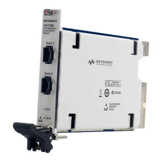
- Page 2 Overview Key Features and Benefits This configuration guide will help you configure your The M9170A is a one-slot PXI attenuator/switch driver PXI attenuator/switch driver module with the expansive module that provides drive control for the Keysight portfolio of Keysight Technologies, Inc., RF and Technologies, Inc.
-
Page 3: Specifications
-continuous Product configurations This document will serve as a step-by-step guide to configure the point-to-point connection between the M9170A with Keysight’s attenuators and electromechanical switches. Please refer to the various figures detailing the type of customized interface cables, switch/attenuator options, and most importantly, the cross-reference tables that provide all the necessary details (i.e. -
Page 4: Table Of Contents
4 | Keysight | M9170A PXI Attenuator/Switch Driver Module - Configuration Guide Five Simple Steps to Configure Your Switching System Step 1. Determine the device’s model and option (DC connector) Example Model: 87104D (SP4T switch) Option: 100 (solder terminal) Step 2. Determine the M9170A’s interface cable option... -
Page 5: Bypass N1811Tl
5 | Keysight | M9170A PXI Attenuator/Switch Driver Module - Configuration Guide Step 5. System ready for operation. Table 1: Selection guide for switches Switch Switch model number Switch M9170A family option 8763A, 8763B, 8763C 011/024 Table 3-B 8764A, 8764B, 8764C... - Page 6 6 | Keysight | M9170A PXI Attenuator/Switch Driver Module - Configuration Guide Table 1-A. Switch option descriptions Option 011 5 Vdc Option 024 24 Vdc Option 201 D-submini 9 pin (f) Option 202 Solder Lug Option 305 5 Vdc with solder terminals...
- Page 7 7 | Keysight | M9170A PXI Attenuator/Switch Driver Module - Configuration Guide Configuration information for switches Table 3-A. Configuration of M9170A (Option 201) to 8762A/B/C/F SPDT (Option 011/024) From M9170A (Option 201) To 8762A/B/C/F SPDT (Option 011/024) Interface cable 20 PIN Bare wire cable...
- Page 8 8 | Keysight | M9170A PXI Attenuator/Switch Driver Module - Configuration Guide Table 3-C. Configuration of M9170 (Option 201) to 8764A/B/C bypass (Option 011/024) From M9170A (Option 201) To 8764A/B/C bypass (Option 011/024) Interface cable 20 PIN Bare wire cable...
-
Page 9: L7204A/B/C Sp4T (Option
9 | Keysight | M9170A PXI Attenuator/Switch Driver Module - Configuration Guide Table 5-A. Configuration of M9170A (Option 201) to 87104A/B/C/D, L7104A/B/C and L7204A/B/C SP4T (Option 100) From M9170A (Option 201) To 87104A/B/C/D, L7104A/B/C and L7204A/B/C SP4T (Option 100) Interface cable... -
Page 10: Black/
10 | Keysight | M9170A PXI Attenuator/Switch Driver Module - Configuration Guide Table 6. Configuration of M9170A (Option 201) to 87204A/B/C SP4T (Option 100) From M9170A (Option 201) To 87204A/B/C SP4T (Option 100) Interface cable 20 PIN Bare wire cable... -
Page 11: Black/Gray
11 | Keysight | M9170A PXI Attenuator/Switch Driver Module - Configuration Guide Table 7-A. Configuration of M9170A (Option 201) to 87106A/B/C/D, L7106A/B/C and L7206A/B/C SP6T (Option 100) and 87406B matrix (Option 100) From M9170A (Option 201) To 87106A/B/C/D, L7106A/B/C and L7206A/B/C SP6T (Option 100) and... -
Page 12: Black/White
5 to C open Blue 6 to C closed Black/Red 6 to C open Table 9. Configuration of M9170A (Option 003) to 8766K, 8767K and 8768K (Option 060) From M9170A (Option 003) To 8766K, 8767K and 8768K (Option 060) Interface cable 8766K... -
Page 13: Black /Violet
13 | Keysight | M9170A PXI Attenuator/Switch Driver Module - Configuration Guide Table 10. Configuration of M9170 (Option 002) to 8767M/8768M From M9170A (Option 002) To 8767M/8768M Interface cable 8767M 8768M 20 PIN 10-Pin Dsub pin number RF path RF path... - Page 14 14 | Keysight | M9170A PXI Attenuator/Switch Driver Module - Configuration Guide Table 11-B. Configuration of M9170 (Option 001) to L7222C and 87222C/D/E transfer (Option 161) From M9170A (Option 001) To L7222C and 87222C/D/E transfer (Option 161) Interface cable 20 PIN 10-Pin Dsub pin number...
-
Page 15: Brown
15 | Keysight | M9170A PXI Attenuator/Switch Driver Module - Configuration Guide Table 12-A. Configuration of M9170A (Option 201) to N1810UL SPDT (Option 202) From M9170A (Option 201) To N1810UL SPDT (Option 202) Interface cable 20 PIN Bare wire cable... - Page 16 16 | Keysight | M9170A PXI Attenuator/Switch Driver Module - Configuration Guide Table 12-B. Configuration of M9170A (Option 501) to N1810UL SPDT (Option 201) From M9170A (Option 501) To N1810UL SPDT (Option 201) Interface cable 20 PIN 9-Pin Dsub pin number...
-
Page 17: Black/Blue
17 | Keysight | M9170A PXI Attenuator/Switch Driver Module - Configuration Guide Table 12-C. Configuration of M9170A (Option 201) to N1810TL SPDT (Option 202) From M9170A (Option 201) To N1810TL SPDT (Option 202) Interface cable 20 PIN Bare wire cable... -
Page 18: Table
18 | Keysight | M9170A PXI Attenuator/Switch Driver Module - Configuration Guide Table 12-D. Configuration of M9170A (Option 501) to N1810TL SPDT (Option 201) From M9170A (Option 501) To N1810TL SPDT (Option 201) Interface cable 20 PIN 9-Pin Dsub pin number... -
Page 19: Table
19 | Keysight | M9170A PXI Attenuator/Switch Driver Module - Configuration Guide Table 12-E. Configuration of M9170A (Option 201) to N1812UL bypass (Option 202) From M9170A (Option 201) To N1812UL bypass (Option 202) Interface cable 20 PIN Bare wire cable... - Page 20 20 | Keysight | M9170A PXI Attenuator/Switch Driver Module - Configuration Guide Table 12-F. Configuration of M9170A (Option 501) to N1812UL bypass (Option 201) From M9170A (Option 501) To N1812UL bypass (Option 201) Interface cable 20 PIN 9-Pin Dsub pin number...
- Page 21 21 | Keysight | M9170A PXI Attenuator/Switch Driver Module - Configuration Guide Table 12-G. Configuration of M9170A (Option 201) to N1811TL bypass (Option 202) From M9170A (Option 201) To N1811TL bypass (Option 202) Interface cable 20 PIN Bare wire cable...
- Page 22 22 | Keysight | M9170A PXI Attenuator/Switch Driver Module - Configuration Guide Table 12-H. Configuration of M9170A (Option 501) to N1811TL bypass (Option 201) From M9170A (Option 501) To N1811TL bypass (Option 201) Interface cable 20 PIN 9-Pin Dsub pin number...
- Page 23 23 | Keysight | M9170A PXI Attenuator/Switch Driver Module - Configuration Guide Configuration information for attenuators Table 13. Configuration of M9170A (Option 003) to 8494G/H, 8495G/H, 8496G/H, 8495K and 8497K programmable attenuators (Option 060) To 8494G/H,8495G/H, 8496G/H,8495K and 8497K From M9170A (Option 003)
- Page 24 24 | Keysight | M9170A PXI Attenuator/Switch Driver Module - Configuration Guide Table 15. Generic bare wire connection Bare wire can be used to drive the switch when no connector option available. From Coaxial wire color Drive control Yellow Vcc 1...
- Page 25 25 | Keysight | M9170A PXI Attenuator/Switch Driver Module - Configuration Guide Interface Cable Drawings Figure 1. Option 001 - 20 pin to 6x10 pin interface cable assembly Figure 2. Option 002 - 20 pin to 10 pin interface cable assembly...
- Page 26 26 | Keysight | M9170A PXI Attenuator/Switch Driver Module - Configuration Guide Interface Cable Drawings (CONT) Figure 3. Option 003 - 20 pin to 12 Pin Viking interface cable assembly Figure 4. Option 501 - 20 pin to 6x9 pin-D-Sub interface cable assembly...
- Page 27 27 | Keysight | M9170A PXI Attenuator/Switch Driver Module - Configuration Guide Interface Cable Drawings (CONT) Figure 5. Option 601 - 20 pin to 2x16 pin interface cable assembly Figure 6. Option 201 - 20 pin to bare wire interface cable assembly...
- Page 28 28 | Keysight | M9170A PXI Attenuator/Switch Driver Module - Configuration Guide Evolving Since 1939 For more information on Keysight Technologies’ products, applications or Our unique combination of hardware, software, services, and people can help you services, please contact your local Keysight reach your next breakthrough.
Need help?
Do you have a question about the M9170A and is the answer not in the manual?
Questions and answers