Table of Contents
Advertisement
Quick Links
Advertisement
Table of Contents

Related Manuals for Keysight Technologies 11713D


Summary of Contents for Keysight Technologies 11713D
- Page 1 Keysight 11713D/E Attenuator/Switch Driver Operating and Service Manual...
- Page 2 FAR 27.401 or DFAR 227.7103-5 (c), adhered to, could result in personal injury or as applicable in any technical data. death. Do not proceed beyond a WARNING notice until the indicated conditions are fully understood and met. Keysight 11713D/E Operating and Service Manual...
-
Page 3: Certification
Certification Keysight Technologies certifies that this product met its published specifications at the time of shipment from the factory. Keysight Technologies further certifies that its calibration measurements are traceable to the United States National Institute of Standards and Technology (NIST, formerly NBS), to the extend allowed by the Institute’s calibration facility, and to the calibration facilities of the other International Standards Organization members. -
Page 4: Safety Considerations
Because of the danger of introducing additional hazards, do not install substitute parts or perform any unauthorized modification to the instrument. Return the instrument to a Keysight Technologies Sales and Service Office for service and repair to ensure that safety features are maintained. -
Page 5: Safety Symbols
WARNING If the device is used in a manner not specified by manufacturer, the device protection may be impaired. Keysight 11713D/E attenuator/switch drivers are designed for indoor use and in an area WARNING with low condensation. CLEAN WITH SLIGHTLY DAMPENED CLOTH CAUTION Clean the outside of the instrument with a soft, lint-free, slightly dampened cloth. -
Page 6: Regulatory Markings
This EMC statement applies to the equipment only for use in business environment. Safety and EMC Requirements This instrument is designed to comply with the following safety and EMC (Electromagnetic Compatibility) requirements: – Low Voltage Directive 2014/35/EU – EMC Directive 2014/30/EU Keysight 11713D/E Operating and Service Manual... -
Page 7: Waste Electrical And Electronic Equipment (Weee) Directive
To contact Keysight for sales and technical support, refer to the support links on the following Keysight websites: – www.keysight.com/find/11713 (product-specific information and support, software and documentation updates) – www.keysight.com/find/assist (worldwide contact information for repair and service) Keysight 11713D/E Operating and Service Manual... - Page 8 THIS PAGE HAS BEEN INTENTIONALLY LEFT BLANK Keysight 11713D/E Operating and Service Manual...
-
Page 9: Table Of Contents
..........17 11713D Front and Rear Panels at a Glance . - Page 10 Exploring the 11713D/E Web Interface over LAN ......98 Servicing the Attenuator/Switch Driver Preparing a Static-Safe Workstation .
- Page 11 ........100 Keysight 11713D/E Operating and Service Manual...
- Page 12 THIS PAGE HAS BEEN INTENTIONALLY LEFT BLANK Keysight 11713D/E Operating and Service Manual...
- Page 13 Connecting accessories for Keysight 11713D/E ....18 Table 2-1 Summary of switches and attenuators connections to 11713D/E . . . 28 Table 2-2 11713D/E front panel and back panel properties .
- Page 14 THIS PAGE HAS BEEN INTENTIONALLY LEFT BLANK Keysight 11713D/E Operating and Service Manual...
-
Page 15: Introduction
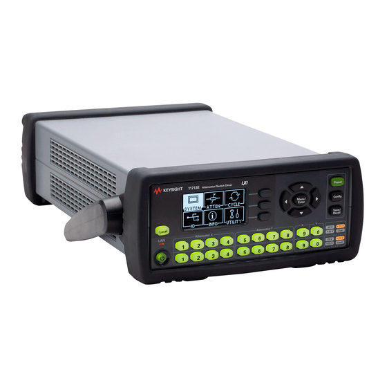
11713D Front and Rear Panels at a Glance 11713E Front and Rear Panels at a Glance This chapter provides an overview of the Keysight 11713D/E attenuator/switch drivers which includes the instruments’ functions and capabilities, compatibility with Keysight switching components, and physical appearances. -
Page 16: Key Features Of Keysight 11713D/E Attenuator/Switch Driver
[b] This TTL specification is 2.4 V at 1 mA. Compatible Keysight Attenuators and Switches The 11713D/E attenuator/switch drivers are designed to drive the following Keysight attenuators and switches. If you are using attenuators and switches made by another supplier, check the... -
Page 17: Connecting Accessories
60 dB, 10 dB steps 84908M 65 dB, 5 dB steps Connecting Accessories Various types of connecting accessories are available to drive Keysight attenuators and switches using the 11713D/E attenuator/switch drivers. Table 1-4 lists the available accessories. Keysight 11713D/E Operating and Service Manual... - Page 18 5061-9694 & 1CM107A, rack mount kit for two instruments 11713E-909 [a] Order this kit to connect two programmable step attenuators in series For the configuration details, refer to Keysight 11713D/E Configuration Guide available at www.keysight.com/find/11713. Keysight 11713D/E Operating and Service Manual...
-
Page 19: 11713D Front And Rear Panels At A Glance
Introduction 11713D Front and Rear Panels at a Glance This section briefly describes the function of the front panel keys of 11713D. Figure 1-1 11713D front panel features 1 LCD screen 2 Softkeys: These unmarked keys are referred to by the text on display next to them. -
Page 20: Figure 1-2 11713D Rear Panel Features
Introduction This section briefly describes the function of the rear panel connectors of 11713D. Figure 1-2 11713D rear panel features 1 ATTEN X: Viking connector for connection to attenuator or switch(es). 2 ATTEN Y: Viking connector for connection to attenuator or switch(es). -
Page 21: 11713E Front And Rear Panels At A Glance
12 Attenuator Y for Bank 1: In the local mode, pushbuttons 5, 6, 7, and 8 change the attenuation setting of an attenuator or change the position of coaxial switch(es) connected to the ATTEN Y connector on the rear panel, for bank 1. Keysight 11713D/E Operating and Service Manual... - Page 22 LED is red. Pressing the key once switches the driver on and the background LED turns to green. 17 Local: Press this key to control the driver from the front panel when it is operating via the remote interfaces. Keysight 11713D/E Operating and Service Manual...
-
Page 23: Figure 1-4 11713E Rear Panel Features
15 GPIB connector: The interface connector from a source device to a listening device for the remote mode of operation. 16 LAN connector: The interface connector for LAN cable. 17 USB connector: The interface connector for Type mini B 5-pin USB cable. 18 Instrument markings Keysight 11713D/E Operating and Service Manual... - Page 24 Introduction THIS PAGE HAS BEEN INTENTIONALLY LEFT BLANK Keysight 11713D/E Operating and Service Manual...
- Page 25 Preparing for Use Connecting to Keysight Attenuators and Switches This chapter provides you important information on how to unpack and check your instrument, how to prepare your instrument for bench operation, and tips on configuring the 11713D/E with Keysight attenuators and switches.
-
Page 26: Installation
If the shipping container or cushioning material is damaged, the contents should be checked both mechanically and electrically. 2 If the contents are damaged or defective, contact your nearest Keysight Technologies Service and Support Office. Refer to “Sales and Technical Support”... -
Page 27: Preparing For Use
– (Top) Handle placed underneath the instrument to assure self- alignment of the instruments when stacked. – (Bottom) Handle tilted to raise the front of the instrument for easier viewing of the front panel. Figure 2-1 Handle positioning for bench operation Keysight 11713D/E Operating and Service Manual... -
Page 28: Connecting To Keysight Attenuators And Switches
Installation Connecting to Keysight Attenuators and Switches The 11713D/E attenuator/switch drivers can be used to drive various switches and attenuators. Table 2-1 shows the summary of switches and attenuators connections to the 11713D/E, with various interface cables for point-to-point connection. - Page 29 Installation Table 2-1 Summary of switches and attenuators connections to 11713D/E (continued) Controlled by 11713D/E cable # of channels Controlled by Switches/attenuators ATTEN X (1-4) SWITCHES (9/0) option required ATTEN Y (5-8) Switches – 8768M Attenuators – 84904K/L/M – 84906K/L –...
- Page 30 Installation Table 2-2 11713D/E front panel and back panel properties Rear panel connectors Front panel pushbuttons Pushbutton Pushbutton number Pin numbers Wire color code LEDs Red (Vcc) White/Brown (Gnd) ATTEN X-3 (S9-A) Gray ATTEN X-4 (S9-B) White/Red ATTEN Y-3 (S0-A)
-
Page 31: Figure 2-2 Typical Connection For A Programmable Four-Section Attenuator
– To use one four-section attenuator assembly, connect an attenuator interface cable either to the ATTEN X output (A6J1) or ATTEN Y output (A6J2). Connect all outputs (two for 11713D and four for 11713E) to have more than four attenuator segments. -
Page 32: Figure 2-3 Typical Connection For 8762 And 8765 Series Coaxial Switches
Installation Figure 2-3 Typical connection for 8762 and 8765 series coaxial switches Keysight 11713D/E Operating and Service Manual... -
Page 33: Figure 2-4 Typical Connection For Relay Driving Circuit
Installation Driving relays – To drive ten devices for 11713D, connect attenuator cables at ATTEN X and Y and switch cables to S9 and S0. – A total of 10 relays may be on at one time if the total current is less than 3.4 A. However, since there are dual transistor and relay drivers, where one driver is on while the other is off, a total of 20 relays may be controlled. - Page 34 Installation THIS PAGE HAS BEEN INTENTIONALLY LEFT BLANK Keysight 11713D/E Operating and Service Manual...
- Page 35 Keysight 11713D/E Attenuator/Switch Driver Operating and Service Manual Specifications General Specifications Environmental Specifications This chapter provides you the specifications of Keysight 11713D/E attenuator/switch drivers.
-
Page 36: Specifications
With handle and bumper 3.6 kg (7.9 lbs) 14.91 inches) 11713E 87.7 mm x 212.7 mm x 364.1 mm (3.45 inches x 8.37 inches x Without handle and bumper 3.2 kg (7.1 lbs) 14.34 inches) Keysight 11713D/E Operating and Service Manual... -
Page 37: Environmental Specifications
GPIB compatibility SH0, AH1, T0, TE0, L2, LE0, SR0, RL1, PP0, DC0, DT0, C0 Environmental Specifications Keysight 11713D/E attenuator/switch drivers are designed to fully comply with Keysight Technologies’ product operating environmental specifications as shown in the table below. Table 3-3... - Page 38 Specifications THIS PAGE HAS BEEN INTENTIONALLY LEFT BLANK Keysight 11713D/E Operating and Service Manual...
-
Page 39: Verification
Keysight 11713D/E Attenuator/Switch Driver Operating and Service Manual Verification Operator’s Check for Local Operation Operator’s Check for Remote Operation This chapter provides you simple instructions to verify Keysight 11713D/E attenuator/switch drivers’ functionality in both local operation and remote (GPIB/USB/LAN) operation. -
Page 40: Operator's Check For Local Operation
3 In addition, if any switching devices is connected (attenuators, relays, or switches), an audible click should be heard from the unit actuated. Pressing any numbered pushbutton should not cause any other pushbutton to change state. Keysight 11713D/E Operating and Service Manual... -
Page 41: Operator's Check For Remote Operation
These procedure verify that the driver can be controlled remotely using GPIB, USB, and/or LAN. 1 Refer to Chapter 7, "Remote Interface Configurations", to connect the 11713D/E to your computer through GPIB, USB, and/or LAN. 2 Once remote connection is available, send the following SCPI commands to the driver and note the changes on front panel LEDs. - Page 42 Verification THIS PAGE HAS BEEN INTENTIONALLY LEFT BLANK Keysight 11713D/E Operating and Service Manual...
- Page 43 Getting Started with the 11713D/E Main Menu of the 11713D/E Save/Recall State Menu This chapter outlines some simple steps to start using the 11713D/E in local operations. Also, functionality of all menus are described to assist operations using the 11713D/E.
-
Page 44: Local Operations
NOTE 1 Connect the AC power supply to the 11713D/E. You should see: – the background LED of the power button is red which indicates that the 11713D/E is in the standby mode. 2 Press the power button once to turn on the 11713D/E. You should see: –... - Page 45 Repeat steps b and c if needed. attenuator type e Model assigned to ATTEN X and ATTEN Y is marked <X> (e.g. P9400A/C) and <Y> (e.g. P9404A/ C) respectively. f To return to the previous screen, press Back softkey. Keysight 11713D/E Operating and Service Manual...
- Page 46 Scroll to highlight Wid th (ms) 3 Enable Pulse using the navigation keys. Drive d Adjust pulse width using Wid th Up and Wid th Down softkeys. e To return to the previous screen, press Back softkey. Keysight 11713D/E Operating and Service Manual...
- Page 47 Output voltage assigned is marked <*>. f To exit this screen, press Back softkey. To drive switches Step 2 — To drive switches, only applicable to the 11713E as the 11713D is NOTE predefined with +24 Vdc supply and no TTL drive. Item Action Illustration a Press Config button.
- Page 48 Scroll to highlight Wid th (ms) 2 Enable Pulse using the navigation keys. Drive d Adjust pulse width using Wid th Up and Wid th Down softkeys. e To return to the previous screen, press Back softkey. Keysight 11713D/E Operating and Service Manual...
- Page 49 (only for 11713E) d On the next screen, press OK softkey to confirm decision or press Cancel softkey to cancel. e Selection is marked <*>. f To exit this screen, press Back softkey. Keysight 11713D/E Operating and Service Manual...
- Page 50 (only for 11713E) d On the next screen, press OK softkey to confirm decision or press Cancel softkey to cancel. e Output voltage assigned is marked <*>. f To exit this screen, press Back softkey. Keysight 11713D/E Operating and Service Manual...
- Page 51 Local Operations Step 3: Configure the 11713D/E connections to attenuators and switches 1 Determine the interface cable option of the 11713D/E. 2 Determine the DC connector option of the attenuator(s) or switch(es). 3 Check for compatibility using Table 1-3 for programmable attenuators and...
- Page 52 [a] If TTL is required, include Option 401. Must order switch with Option 403 (current interrupt) as switch cannot withstand continuous current supplied by 11713D/E. 4 For more details, refer to Keysight 11713D/E Configuration Guide available at www.keysight.com/find/11713. Keysight 11713D/E Operating and Service Manual...
-
Page 53: Main Menu Of The 11713D/E
110 dB, 0, 0). d Press Menu/Enter button again to return to main menu. Attenuation value on display changes according to the input from the front panel pushbuttons or through the virtual web interface: Keysight 11713D/E Operating and Service Manual... - Page 54 Local Operations – Pushbutton LED ON — attenuation card selected (attenuation applied) on corresponding attenuator section – Pushbutton LED OFF — thru path selected (attenuation lifted) on corresponding attenuator section Keysight 11713D/E Operating and Service Manual...
- Page 55 Press Clear All. b On the next screen, press OK Clear cycle for all softkey to confirm decision or channels press Cancel softkey to cancel. c.Note that relay cycle for all channels is 0. Keysight 11713D/E Operating and Service Manual...
- Page 56 Local Operations Function Action Illustration a Press Save All. Save cycle for all b On the next screen, Cycles saved. channels appears and this confirms all channels’ cycles are saved. Keysight 11713D/E Operating and Service Manual...
- Page 57 Press Menu/Enter button when – Firmware INFO icon is highlighted. revision c Press Menu/Enter button again to – GPIB address return to main menu. – LAN IP – USB address – MAC address Keysight 11713D/E Operating and Service Manual...
- Page 58 Cancel softkey to cancel. a Scroll to highlight LAN reset using the navigation keys, then press Yes softkey. Reset LAN b On the next screen, press OK softkey to confirm decision or press Cancel softkey to cancel. Keysight 11713D/E Operating and Service Manual...
- Page 59 Local Operations Preset menu The preset function is used to apply full attenuation or open all switching paths (all LEDs light ON). For more information: “List of default values” on page 61. Keysight 11713D/E Operating and Service Manual...
-
Page 60: Save/Recall State Menu
Scroll to the desired state to recall configuration (e.g. STATE 2) using the navigation keys. To recall state c Press Recall State softkey to reinstate configuration. d Press Menu/Enter button again to return to main menu. Keysight 11713D/E Operating and Service Manual... - Page 61 Blank: Backup operation not performed. Save/Recall Settings that permit Save/Recall of a setup state. In the table, states that can be saved/recalled are denoted in the following manner: *: Save/Recall can be performed. Blank: Save/Recall cannot be performed. Keysight 11713D/E Operating and Service Manual...
- Page 62 Local Operations THIS PAGE HAS BEEN INTENTIONALLY LEFT BLANK Keysight 11713D/E Operating and Service Manual...
- Page 63 Keysight 11713D/E Attenuator/Switch Driver Operating and Service Manual Remote Operations Configuring Remote Interface Control using Keysight IO Libraries Suite Programming Guide (SCPI) This chapter provides the programming guide for the 11713D/E in SCPI commands.
-
Page 64: Remote Operations
Each device on the GPIB (IEEE-488) interface must have a unique address. You can set the 11713D/E’s address to any value between 0 and 30. The attenuator/switch driver is shipped with a default address set to 28. The GPIB address is stored in non-volatile memory and does not change when the driver is switched off or after a remote interface reset. - Page 65 Connectivity Guide. If you have installed other I/O software, refer to the documentation that accompanies the software. LAN configuration The 11713D/E has three LAN operating modes: – Dynamic mode (Dynamic Host Configuration Protocol or DHCP) – Auto IP mode (Local PC Control or isolated LAN) –...
-
Page 66: Control Using Keysight Io Libraries Suite
Keysight IO Libraries Suite (when the IP address of the 11713E is 10.74.76.53). Please ensure the remote instrument name is selected. Figure 6-1 Example of control using Keysight IO Libraries Suite Keysight 11713D/E Operating and Service Manual... -
Page 67: Programming Guide (Scpi)
– The following command closes a range of channels. When you specify a range of channels, the range may contain invalid channels (they are ignored), but the first and last channel in the list must be valid: ROUTe:CLOSe (@101:109) Keysight 11713D/E Operating and Service Manual... - Page 68 (00-nn, range model dependent). For example: 103 or 104 or 108. For detailed information, refer to Rules for using a channel or scan list section. ROUTe:OPEn <channel_list> Query? Set? Numeric representation format: Integer (for Set/Return Parameters example, 8) 101 (11713D) Minimum 101, 201 (11713E) Keysight 11713D/E Operating and Service Manual...
- Page 69 Query? Set? Numeric representation format: Integer (for Set Parameters example, 8) Minimum Maximum Units None Examples To close all channels: ROUTe:CLOSe:ALL Related Commands ROUTe:CLOSe ROUTe:OPEn ROUTe:OPEn:ALL ROUTe:OPEn:ALL Opens all switching paths. ROUTe:OPEn:ALL Query? Set? Keysight 11713D/E Operating and Service Manual...
- Page 70 KTP9404 | KTU9400 | KTU9397 Minimum Maximum Units None Examples To set the attenuator or solid state switch type to KTP9400: :CONF:BANK1:X KTP9400 To query the set attenuator or solid state switch type: :CONFigure[:BANK1]:Y? :CONFigure:BANK2:X? :CONFigure:BANK2:Y? Keysight 11713D/E Operating and Service Manual...
- Page 71 To set the supply voltage for bank 1 to P24v: CONF:BANK1 P24v To query the set supply voltage for bank 1 and bank 2: CONFigure:BANK1? CONFigure:BANK2? Related Commands :CONFigure[:BANK1]:X/:CONFigure[:BANK1]:Y :CONFigure:BANK2:X/:CONFigure:BANK2:Y CONFigure[:BANK1]:TTL/CONFigure:BANK2:TTL CONFigure[:BANK1]:PULSe:DRIVe CONFigure:BANK2:PULSe:DRIVe CONFigure[:BANK1]:PULSe:WIDTh CONFigure:BANK2:PULSe:WIDTh ATTenuator[:BANK1]:X/ATTenuator[:BANK1]:Y ATTenuator:BANK2:X/ATTenuator:BANK2:Y Keysight 11713D/E Operating and Service Manual...
- Page 72 Related Command s :CONFigure[:BANK1]:X/:CONFigure[:BANK1]:Y :CONFigure:BANK2:X/:CONFigure:BANK2:Y CONFigure[:BANK1]/CONFigure:BANK2 CONFigure[:BANK1]:PULSe:DRIVe CONFigure:BANK2:PULSe:DRIVe CONFigure[:BANK1]:PULSe:WIDTh CONFigure:BANK2:PULSe:WIDTh ATTenuator[:BANK1]:X/ATTenuator[:BANK1]:Y ATTenuator:BANK2:X/ATTenuator:BANK2:Y CONFigure[:BANK1]:PULSe:DRIVe CONFigure:BANK2:PULSe:DRIVe Sets or returns the instrument’s pulse drive operating mode: 0 for standard mode and 1 for pulse mode. CONFigure[:BANK1]:PULSe:DRIVe <bool> CONFigure:BANK2:PULSe:DRIVe <bool> Keysight 11713D/E Operating and Service Manual...
- Page 73 CONFigure[:BANK1]:TTL/CONFigure:BANK2:TTL CONFigure[:BANK1]:PULSe:WIDTh CONFigure:BANK2:PULSe:WIDTh ATTenuator[:BANK1]:X/ATTenuator[:BANK1]:Y ATTenuator:BANK2:X/ATTenuator:BANK2:Y CONFigure[:BANK1]:PULSe:WIDTh CONFigure:BANK2:PULSe:WIDTh Sets or returns the instrument’s pulse drive width. CONFigure[:BANK1]:PULSe:WIDTh <NRf+> CONFigure:BANK2:PULSe:WIDTh <NRf+> Query? Set? Numeric representation format: Integer (for Set/Return Parameters example, 8) Minimum Maximum Units milliseconds Keysight 11713D/E Operating and Service Manual...
- Page 74 CONFigure[:BANK1]/CONFigure:BANK2 CONFigure[:BANK1]:TTL/CONFigure:BANK2:TTL CONFigure[:BANK1]:PULSe:DRIVe CONFigure:BANK2:PULSe:DRIVe ATTenuator[:BANK1]:X/ATTenuator[:BANK1]:Y ATTenuator:BANK2:X/ATTenuator:BANK2:Y CONFigure[:BANK1]:PULSe:DRIVe, CONFigure:BANK2:PULSe:DRIVe, NOTE CONFigure[:BANK1]:PULSe:WIDTh and CONFigure:BANK2:PULSe:WIDTh SCPI commands are only supported for 11713D and 11713E instruments. ATTenuator[:BANK1]:X/ATTenuator[:BANK1]:Y ATTenuator:BANK2:X/ATTenuator:BANK2:Y Sets the attenuation level of corresponding attenuator(s). ATTenuator[:BANK1]:X <NR1> ATTenuator:BANK2:X <NR1> Query? Set? Set/.Return Parameters Attenuation level of corresponding attenuator...
- Page 75 110, 210 (11713E) Units None Examples To query the number of cycles: DIAG:REL:CYCL? (@1,8)/DIAG:REL:CYCL? (@1:8) DISPlay:ATTenuation Turns the front panel display to the ATTEN page. DISPlay:ATTenuation Query? Set? Set Parameters Minimum Maximum Units None Keysight 11713D/E Operating and Service Manual...
- Page 76 Set? Set Parameters Minimum Maximum Units None Examples DISP:IO Related Command s DISPlay:ATTenuation DISPlay:SYSTem DISPlay:CYCLe DISPlay:INFormation DISPlay:UTILity HCOPy:SDUMp:DATA? DISPlay:SYSTem Turns the front panel display to the SYSTEM page. DISPlay:SYSTem Query? Set? Set Parameters Minimum Keysight 11713D/E Operating and Service Manual...
- Page 77 Turns the front panel display to the CYCLE page. DISPlay:CYCLe Query? Set? Set Parameters Minimum Maximum Units None Examples DISP:CYCL Related Commands DISPlay:ATTenuation DISPlay:IO DISPlay:SYSTem DISPlay:INFormation DISPlay:UTILity HCOPy:SDUMp:DATA? DISPlay:INFormation Turns the front panel display to the INFO page. DISPlay:INFormation Keysight 11713D/E Operating and Service Manual...
- Page 78 DISPlay:SYSTem DISPlay:CYCLe DISPlay:UTILity HCOPy:SDUMp:DATA? DISPlay:UTILity Turns the front panel display to the UTILITY page. DISPlay:UTILity Query? Set? Set Parameters Minimum Maximum Units None Examples DISP:UTIL Related Command s DISPlay:ATTenuation DISPlay:IO DISPlay:SYSTem DISPlay:CYCLe DISPlay:INFormation HCOPy:SDUMp:DATA? Keysight 11713D/E Operating and Service Manual...
- Page 79 “-350,Too Many Errors”. SYSTem:ERRor? Query? Yes, query only Set? Return Parameters Integer, String Minimum Maximum Units None Examples To query the next error from the queue: SYST:ERR? Keysight 11713D/E Operating and Service Manual...
- Page 80 Sets the interface in the Remote state, which disables all front panel controls except the Local key. Pressing the Local key in the Remote state returns the front panel to the Local state. SYSTem:REMote Query? Set? Set Parameters Minimum Maximum Units None Keysight 11713D/E Operating and Service Manual...
- Page 81 To query the initial control connection port number for Sockets communications: SYST:COMM:TCP:CONT? Related Commands SYSTem:ERRor? SYSTem:PREset SYSTem:REMote SYSTem:PERSona:MANufacturer Sets the manufacturer string returned by Query. *IDN? SYSTem:PERSona:MANufacturer <quoted string> Query? Set? Set/Return Parameters String Minimum Maximum Units None Keysight 11713D/E Operating and Service Manual...
- Page 82 Remote Operations Examples To set the manufacturer string to “Keysight Technologies”: SYST:PERS:MAN “Keysight Technologies” To query the set manufacturer string: SYSTem:PERS:MAN? Related Command s SYSTem:PERSona:MANufacturer:DEFault SYSTem:PERSona:MANufacturer:DEFault Sets the manufacturer string to default (Keysight Technologies). SYSTem:PERSona:MANufacturer:DEFault Query? Set? Set/Return Parameters String...
- Page 83 - A binary block of data, consisting of bytes of setup information. The number of bytes is a dynamic number that is read and allocated by the instrument’s firmware. - SYSTem:SET query operates the same as the *LRN? query SYSTem:SET <Binary Block> Query? Set? Set/Return Parameters Binary Data Minimum Keysight 11713D/E Operating and Service Manual...
- Page 84 *CLS Related Command s *IDN? *OPC? *RST *ESE Programs the Standard Event Status Enable register bits. The programming determines which events of the Standard Event Status Event register (refer to “*ESR?”) are allowed to Keysight 11713D/E Operating and Service Manual...
- Page 85 Related Commands *ESR? *SRE *STB? *ESR? Reads and clears the Standard Event Status Event register. The bit configuration of this register is the same as the Standard Event Status Enable register (refer to “*ESE”). *ESR? Keysight 11713D/E Operating and Service Manual...
- Page 86 *ESR? Related Command s *ESE *SRE *STB? *IDN? Requests the switch/attenuator driver to identify itself. It returns the data in four fields separated by commas. For example, Keysight Technologies, 11713E, MY00000000, A.00.01. Field Description Keysight Technologies Manufacturer 11713x Model number...
- Page 87 Related Commands *CLS *IDN? *RST *RST Resets the switch/attenuator driver to the following factory-defined states: - All channels in both banks will be lighted on. *RST Query? Set? Set Parameters Minimum Maximum Units None Keysight 11713D/E Operating and Service Manual...
- Page 88 QUES - Questionable Status Summary *SRE <Integer> Query? Set? Set/Return Parameters Integer (register binary value) Minimum Maximum Units None Examples To set the bit in the status byte enable register to 128: *SRE 128 Keysight 11713D/E Operating and Service Manual...
- Page 89 The return string includes “SYSTem:SET” command header that can be used directly, provided the receiver accepts binary data. *LRN? Query? Yes, query only Set? Return Parameters (Optional) Binary Data Minimum Maximum Units None Keysight 11713D/E Operating and Service Manual...
- Page 90 Remote Operations Examples To return all the saved EEPROM values: *LRN? Related Command s *CLS *IDN? *OPC? *RST SYSTem:SET Keysight 11713D/E Operating and Service Manual...
- Page 91 Exploring the 11713D/E Web Interface over LAN This chapter provides you information and steps to establish remote connections with the Keysight 11713D/E attenuator/switch drivers via GPIB, USB, and LAN. You will also be introduced to the 11713D/E web interface over LAN.
-
Page 92: Remote Interface Configurations
If you have installed any other I/O software, refer to the documentation NOTE included with that software. 7 The 11713D/E is shipped from the factory with a default GPIB address of 28. To change the address, refer to table below: Keysight 11713D/E Operating and Service Manual... - Page 93 92 for more information on installing the Keysight IO Libraries software. 1 After the I/O software is installed on your computer, connect a 11713D/E to your computer using a Type Mini-B 5 pin USB cable. 2 Make sure power is applied to your computer and verify that the operating system is fully booted.
- Page 94 Apply power to 11713D/E and background LED color turns red, indicating standby mode. connected to d Allow 11713D/E to warm up for 15 seconds, then press the ON button (LED turns from red to green). Keysight 11713D/E Operating and Service Manual...
- Page 95 I/O software on your computer. Use the Connectivity Expert utility of the Keysight IO Libraries Suite to add the 11713D/E and verify a connection. When identifying the instrument, it is easiest if you use the IP address noted in step 3 above.
- Page 96 Apply power to 11713D/E and background LED color turns red, indicating standby mode. 11713D/E are d Allow 11713D/E to warm up for 15 seconds, then press the ON button (LED turns from red to green). turned on a Press Menu/Enter button on the front panel of 11713D/E.
- Page 97 I/O software on your computer. Use the Connectivity Expert utility of the Keysight IO Libraries Suite to add the 11713D/E and verify a connection. When identifying the instrument, it is easiest if you use the IP address noted in step 3 above.
- Page 98 4 Exit the Options window. 5 Enter the IP address of the 11713D/E in the Address field and press return. Use the 11713D/E’s front panel utility menu to read the IP address. 6 After entering the appropriate IP address, the 11713D/E Web Interface’s Welcome Window should appear.
-
Page 99: Figure 7-1 11713D/E Web Interface's Welcome Window
1 In the Home window, click Control Instrument on the top bar of the window. 2 You can view the virtual front panel of 11713D/E. 3 Now, you can control this device remotely, similar to the front panel of the actual instrument. -
Page 100: Figure 7-3 Enable Password Window
Remote Interface Configurations Figure 7-3 Enable Password window 5 Enter a new password and click Enable Password if you wish to enable password for controlling the instrument. Keysight 11713D/E Operating and Service Manual... - Page 101 Keysight 11713D/E Attenuator/Switch Driver Operating and Service Manual Servicing the Attenuator/Switch Driver Preparing a Static-Safe Workstation Maintenance and Adjustments This chapter provides the procedures for removal and replacement of major assemblies in the 11713D/E and the list of replaceable parts.
- Page 102 – PC board assembly edge-connector contacts may be cleaned by using a lint-free cloth with a solution of 80% electronics-grade isopropyl alcohol and 20% deionized water. This should be performed at a static-safe workstation. Keysight 11713D/E Operating and Service Manual...
- Page 103 Be sure to select the correct fuse rating for the selected line voltage. Do not NOTE use repaired fuses or short circuited fuse-holders. To do so could cause a shock or fire hazard. Adjustment The 11713D/E attenuator/switch driver has no internal electrical or mechanical adjustments. Keysight 11713D/E Operating and Service Manual...
- Page 104 Servicing the Attenuator/Switch Driver THIS PAGE HAS BEEN INTENTIONALLY LEFT BLANK Keysight 11713D/E Operating and Service Manual...
- Page 105 This information is subject to change without notice. Always refer to the Keysight website for the latest revision. © Keysight Technologies 2020 Edition 1, January 31, 2020 Printed in Malaysia 11713-90028 www.keysight.com...
Need help?
Do you have a question about the 11713D and is the answer not in the manual?
Questions and answers