Table of Contents
Troubleshooting

Related Manuals for Keysight Technologies M9195A


Summary of Contents for Keysight Technologies M9195A
- Page 1 Startup Guide For the User Guide, software and other important documentation, see the M9195A/B Software and Product Information CD. Keysight M9195A/B PXIe Digital Stimulus/Response with PPMU: 250 MHz, 16 channel...
- Page 2 WITHOUT NOTICE, IN FUTURE EDI- without prior agreement and written con- ment of Defense FAR Supplement TIONS. FURTHER, TO THE MAXIMUM sent from Keysight Technologies, Inc. as (“DFARS”) 227.7202, the U.S. govern- EXTENT PERMITTED BY APPLICABLE governed by United States and interna-...
- Page 3 Safety Information Do Not Remove Instrument Cover The following general safety precau- tions must be observed during all Only qualified, service-trained person- phases of operation of this instrument. nel who are aware of the hazards Failure to comply with these precau- involved should remove instrument tions or with specific warnings or oper- covers.
- Page 4 Safety Symbols Products display the following sym- ICES/NMB-001 bols: ISM GRP 1-A Warning, risk of electric Notice for European Community: This MSIP-REM-Kst shock product complies with the relevant -BLM9195A European legal Directives: EMC Direc- South Korean Class A EMC Declara- tive (2004/108/EC) and Low Voltage Refer to manual for addi- tion.
-
Page 5: Table Of Contents
M9195A versus M9195B ........ - Page 6 M9195A/B Front Panel Features ........
-
Page 7: Product Overview
M9595A/B PXIe Digital Stimulus/Response Startup Guide Product Overview The M9195A and M9195B modules are PXIe Digital Stimulus/Response (DSR) modules. Both offer: – 16 bidirectional channels with per-pin programmable logic levels – High speed pattern application and clock rates up to 250Mz –... -
Page 8: M9195A Versus M9195B
Functional Overview At its most basic level, the M9195A/B DSR modules deliver test vectors to a DUT at up to 250 MHz and compares responses to expected values. Each of 16 channels can be configured for PPMU operation. Four high voltage, and four open drain channels are also available. -
Page 9: Follow The Startup Sequence
Follow the Startup Sequence Follow the Startup Sequence Closely follow the startup process flow in this document. Deviating from the sequence can cause unpredictable system behavior, damage your system, and may cause personal injury. Keysight M9195A/B PXIe Digital Stimulus/Response Startup Guide... -
Page 10: Related Documentation
Manuals and Help Systems Other Keysight PXI and PXIe Modular Systems www.keysight.com/find/pxi M9195A/B Documents and Help Systems - Introduction: This document summarizes current information on the M9195A/B modules including: -- current release details -- hardware and software requirements -- known issues This document file is on the Software and Product Information CD that came with your system. - Page 11 Introduction. On the Software and Product Information CD Bring up the CD main menu to check all the M9195A/B documents and help systems (including accessory guides) available on the M9195A/B CD. To quickly get started with the M9195A/B installation process, refer to the M9195A/B Quick Start Poster shipped with the M9195A/B module.
-
Page 12: Step 1: Unpack And Inspect The Module
(see warranty information at beginning of this document). To avoid damage when handling a module, do not touch exposed connector pins. Keysight M9195A/B PXIe Digital Stimulus/Response Startup Guide... -
Page 13: Returning A Module For Service
Step 1: Unpack and Inspect the Module Returning a module for service Should it become necessary to return your M9195A/B module for repair or calibration, follow the steps below: It is recommended that you include all cables with the module in the case that you return the module for repair or calibration. -
Page 14: Step 2: Verify M9195A/B Shipment Contents
Recommended due date for calibration Any options or accessories (such as cables) ordered with your “M9195A/B Accessories” M9195A module (see page 9). M9195A Options The following options are included as standard features in the M9195A. Option Number Description M9195A-M12 Memory, 125 Mvectors/Channel M9195A-S04... -
Page 15: M9195B Options
Multi-module sync this option includes an SMB-to-SMB sync connector shipped separately from the M9195B M9195A/B Accessories The following table lists the accessories available for the M9195A/B PXIe Digital Stimulus Response module. For more information on accessories, see “Accessories” on page 38. -
Page 16: Step 3: Install The Software
The IO Libraries Suite must be installed prior to installing the M9195A/B driver. - M9195A/B instrument software, which includes the Soft Front Panel (SFP), device drivers (IVI-C and IVI-COM), and documentation for the M9195A/B PXIe Digital Stimulus/Response module. This software is available on the Software and Product Information CD and at www.keysight.com/find/M9195B. -
Page 17: Software Installation Procedure
Follow the installer prompts to install the IO libraries. Install the M9195A/B product software: Using the Keysight M9195A/B PXIe Digital Stimulus/Response Software and Product Information CD (M9195-10002), launch the installer. When the Install Wizard starts, click the Next button. - Page 18 For additional documentation, go further down the Star button listing to Start>All Programs>Keysight Instrument Drivers>KtMDsr Digital Stimulus Response. The display will appear something like: Here click on the icons for: -- Programming Guide -- KtMDSr Introduction Keysight M9195A/B PXIe Digital Stimulus/Response Startup Guide...
-
Page 19: Step 4: Install The Module
When powering-up the PXI chassis and during the first DSR driver initialization after power-up (from the IVI API or from the M9195A/B Soft Front Panel) make certain that no device–under– test (DUT) is connected to the M9195A/B module. Keysight M9195A/B PXIe Digital Stimulus/Response Startup Guide... -
Page 20: Module Installation Procedure
(top and bottom). Slide the module to the rear of the chassis and ensure that the injector/ejector handle is pushed down in the unlatched (downward) position. Power Keysight M9195A/B PXIe Digital Stimulus/Response Startup Guide... - Page 21 Cable Interface in the chassis to the PC host per the instructions that came with the Cable Interface. Power up the PXI chassis. Reboot the PC host. Proceed to Step 5: Verify Operation of the Keysight M9195A/B PXIe Digital Stimulus/Response module (“Step 5: Verify Operation of the M9195A/B Module”...
-
Page 22: Step 5: Verify Operation Of The M9195A/B Module
Step 5: Verify Operation of the M9195A/B Module Step 5: Verify Operation of the M9195A/B Module In this step you will verify correct operation of the Keysight M9195A/B PXIe Digital Stimulus/Response module. Before running Self Test or Automatic Corrections, ensure that all required software is installed, the chassis is powered on, and all front panel cabling is removed. - Page 23 Step 5: Verify Operation of the M9195A/B Module The details on the M9195 should appear as shown Figure 2 below. Filter Instruments box Figure 2 Bring Up M9195A/B Details with Connection Expert Keysight M9195A/B PXIe Digital Stimulus/Response Startup Guide...
-
Page 24: Bring Up Soft Front Panel
Step 5: Verify Operation of the M9195A/B Module Bring Up Soft Front Panel The M9195A/B Soft Front Panel (SFP) is required to run Self Test, perform Automatic Corrections, and more. To run the SFP: Select Start > All Programs > Keysight > MDsr > MDsr SFP. - Page 25 Step 5: Verify Operation of the M9195A/B Module From the Connect to Instrument dialog box, select the M9195A/B module that you want to verify, then click Connect. Figure 4 Connect to Instrument dialog box The SFP should now appear as shown below in...
-
Page 26: Conduct A Self Test
Does the M9195A/B (SFP) connect?. Conduct a Self Test Now the M9195A/B is ready to run Self Test from the Soft Front Panel. Before you initiate the Self Test, (a) Disconnect all cables (for accuracy and to prevent damage) (b) Save any data that you need (waveforms, cycle instructions, etc.), as Self Test will erase the memory in the module. - Page 27 Step 5: Verify Operation of the M9195A/B Module Click Yes when all cables have been removed. Figure 7 Initiate the M9195A/B Self Test On multi-module installations the Status LED will briefly turn green at the start and near the end of Self Test.
-
Page 28: Step 6: Execute Automatic Corrections
Automatic Corrections is initiated from the Soft Front Panel. Automatic Corrections executes a function that automatically calculates corrections for the M9195A/B. It does not require a calibration fixture or measurement equipment. The name of the specific function is Execute Automatic Corrections. -
Page 29: Automatic Corrections Procedure
Step 6: Execute Automatic Corrections Automatic Corrections procedure Turn on the M9195A/B system, and allow it to warm up for a minimum of 30 minutes. Remove all cables from the front of the M9195A/B. You must remove all cables from the M9195A/B before executing Automatic Corrections. - Page 30 – Use Window50Hz if you notice power line noise and your local power is 50 – Use Window60Hz if you notice power line noise and your local power is 60 Now, to run Automatic Corrections, Click the Execute Automatic Corrections... button in Figure Keysight M9195A/B PXIe Digital Stimulus/Response Startup Guide...
- Page 31 Step 6: Execute Automatic Corrections If you have not yet removed all cables connected to the M9195A/B, disconnect them as you are prompted by the SFP (as in Figure 11). Figure 11 Reminders to disconnect inputs Wait for Automatic Corrections to run. This may take several minutes.
-
Page 32: Step 7: Check M9195B Licensing (Optional)
The licensing status of a module can be checked by selecting it through the Software Front Panel (SFP) and then going to the About Box in the Help drop-down menus. In the About Box, installed options will be listed after “System Options:”. Keysight M9195A/B PXIe Digital Stimulus/Response Startup Guide... -
Page 33: Checking Hardware Upgrade Option Licensing
In a multi-module configuration, the licensed features are the “least common” across all modules. For example, in a two module M9195B configuration, if one is licensed for M06 and the other from M12, the multi-module installation will operate with M06. Keysight M9195A/B PXIe Digital Stimulus/Response Startup Guide... -
Page 34: High-Level Diagnostic Tools, Processes And References
To avoid damage when handling a module, do not touch exposed connector pins. Specifications The Specification Guide for the M9195A/B is included on the Software and Product Information CD. Please check the Keysight website at www.keysight.com/find/M9195B for the latest updates to this information. - Page 35 If the status LED does not go from solid green to solid blue after the Soft Front Panel comes up and connects with the M9195A/B, there may be an LED problem. If the Soft Front Panel does not come up, see “Check...
-
Page 36: Status Led Summary
High-Level Diagnostic Tools, Processes and References Status LED Summary First, check the M9195A/B front panel Status LED. When power is first applied, the LED starts in the Off state and then changes to green after a few moments when PCI enumeration takes place. In general, when the Status LED is solid green the module is working correctly. -
Page 37: Chassis Cooling Checks
“Run Self Test” on page 33 Check Module Status LED Once the SFP connects to the M9195A/B, select Instrument and then Identity tabs. Click on Identify Indicator On. If the blue LED does not pulse on and off, run Self Test (see page 33). - Page 38 High-Level Diagnostic Tools, Processes and References Check Module Temperature After the SFP connects to the M9195A/B, select Instrument and then Temperature tabs. Choose Single or Continuous and the temperature will appear: If the FPGA temperature is over 85 C (this wil cause the Status LED to go red as...
- Page 39 C, return the board for evaluation and repair. If the FPGA temperature stays below 85 C, re-run Self Test, and if the Fault condition above persists, see “Returning a module for service” on page 7. Keysight M9195A/B PXIe Digital Stimulus/Response Startup Guide...
- Page 40 "Fault condition: Undervoltage in FPGA due to excessive current draw" Power down chassis and disconnect all cables from M9195A/B. If problem persists on power up, power down again and re-seat the M9195A/B in the PXIe card cage. If problem persists, see “Returning a...
-
Page 41: Installing Hardware License Options
Note that the information going to KSM includes both the “PC S/N” and the serial number of the M9195B. Once the KSM receives the host identification data, it emails a license file for the Hardware Options Upgrade Entitlement Certificate. Keysight M9195A/B PXIe Digital Stimulus/Response Startup Guide... - Page 42 Options Upgrade dialog box and click on ‘Apply’ to activate the options. PCSERNO,SA12345678,MY12345678 Figure 16 Hardware Options Upgrades after Licenses Installed To check that the Hardware Upgrade Option is installed, go to the SFP About dialog box to see if it is displayed. Keysight M9195A/B PXIe Digital Stimulus/Response Startup Guide...
-
Page 43: M9195A/B Front Panel Features
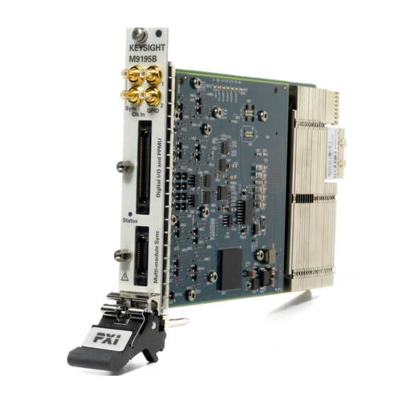
Ppmu_Sense04 Ppmu_Sense01 Ppmu_Sense02 Ppmu_Sense00 Ppmu_Sense03 Latch/GND Latch/GND Figure 17 M9195A/B Front Panel and Connector Pin-out * The CLK In SMB connector allows you to input a 10 MHz or 100 MHz reference clock Keysight M9195A/B PXIe Digital Stimulus/Response Startup Guide... -
Page 44: Accessories
– Y1253A works with both A and B models This is a prototyping board that may be connect to the Digital IO and PPMU connector on the M9195A/B front panels. It supports development of test fixtures for interfacing to DUTs. - Page 46 This information is subject to change without notice. © Keysight Technologies 2015-2020 Fifth Edition, November 2020 Printed in Malaysia M9195-90002 www.keysight.com...
Need help?
Do you have a question about the M9195A and is the answer not in the manual?
Questions and answers