Table of Contents
Advertisement
Quick Links
Datex-Ohmeda Inc.
3 Highwood Drive
Tewksbury, MA 01876
Tel. (978) 640-0460 Fax (978) 640-0469
www.us.datex-ohmeda.com
AS/3 Compact Monitor, CS/3 Compact Monitor
Datex-Ohmeda
Technical Reference Manual
All specifications are subject to change without notice.
P.O. Box 900, FIN-00031
DATEX-OHMEDA, FINLAND
Tel. +358 10 394 11 Fax +358 9 146 3310
www.datex-ohmeda.com
Instrumentarium Corp. All rights reserved.
Document No. 896623
February 2000
Datex-Ohmeda Division,
Instrumentarium Corp.
Advertisement
Table of Contents
Troubleshooting

Subscribe to Our Youtube Channel
Related Manuals for Datex-Ohmeda AS/3 Compact Monitor


Summary of Contents for Datex-Ohmeda AS/3 Compact Monitor
- Page 1 Datex-Ohmeda AS/3 Compact Monitor, CS/3 Compact Monitor Technical Reference Manual All specifications are subject to change without notice. Document No. 896623 February 2000 Datex-Ohmeda Inc. Datex-Ohmeda Division, 3 Highwood Drive Instrumentarium Corp. Tewksbury, MA 01876 P.O. Box 900, FIN-00031 DATEX-OHMEDA, FINLAND Tel.
- Page 2 NOTICE Intended purposes The Datex-Ohmeda AS/3 Compact Monitor is a multiparameter patient monitor intended for the physiological monitoring of hospitalized patients. It is indicated for monitoring anesthetized patient’s relaxation, hemodynamic, ventilation, gas exchange, regional perfusion and neurophysiological parameters. The system is indicated for use by qualified medical personnel only.
- Page 3 Master table of contents Datex-Ohmeda AS/3 Compact Monitor and CS/3 Compact Monitor Technical Reference Manual, 896 623 Folder 1(2), PART I, General Service Guide Document No. Updated Updated Description Introduction, System description, Installation, Interfacing, Functional check, General troubleshooting 896 623...
-
Page 5: Table Of Contents
Table of contents TABLE OF CONTENTS AS/3 Compact Monitor, CS/3 Compact Monitor TABLE OF CONTENTS TABLE OF FIGURES 1 INTRODUCTION 1.1 Notes to the reader ............................2 1.1.1 Related Documentation........................2 1.1.2 Conventions used..........................3 1.2 Safety Precautions.............................6 1.2.1 Warnings ............................6 1.2.2 Cautions ............................7 2 SYSTEM DESCRIPTION 2.1 Introduction...............................9... -
Page 6: Table Of Figures
4.1.1 Interconnection Datex-Ohmeda Monitors ..................46 4.1.2 Setting the Interfacing Parameters ....................47 4.1.3 Setting the Interfacing Parameters for the Compact Monitor ..............47 4.2 Interfacing with Datex-Ohmeda Monitors via UPINET Board, B-UPINET ............47 4.3 Interfacing Monitors via M-INT........................48 4.3.1 Connection to Datex-Ohmeda Monitors....................48 4.3.2 Connection to Critikon Dinamap 1846SX, Abbott Oximetrix 3 and Baxter Explorer ......49... - Page 7 Figure 8 Rear Panel with Memory, CPU and UPINET Boards ...................16 Figure 9 Rear Panel with NET, CPU and UPI Boards. NET and UPI Boards can be replaced by UPINET board.....16 Figure 10- Datex-Ohmeda Compact Airway Module ....................39 Figure 11 Scavenging through Ventilator Reservoir....................40 Figure 12 Connection Directly to a Scavenging System ..................40...
- Page 8 Datex-Ohmeda AS/3 CM and CS/3 CMC Document No. 896623...
-
Page 9: Introduction
General Service Guide INTRODUCTION Datex-Ohmeda AS/3 Compact Monitor is a cardiac and respiratory monitoring device used during anesthesia, recovery and short transports. Datex-Ohmeda CS/3 Compact Monitor is designed for monitoring in intensive care units. The monitor consists of the CM frame and modules. There are single and double width modules containing one or more parameters. -
Page 10: Notes To The Reader
This technical reference manual is divided into two parts: • The Part I gives to the reader overview of the AS/3 Compact Monitor and CS/3 Compact Monitor. This part of the manual contains also the information you need to unpack, install and test the monitors. -
Page 11: Conventions Used
General Service Guide 1.1.2 Conventions used Throughout this manual, the following conventions are used to distinguish procedures or elements of text: Sign the performed procedure in the check list. To help you find and interpret information easily, the manual uses consistent text formats for certain text types: Hard Keys Names of the hard keys on the Remote Controller, Command Board and modules are written in the... - Page 12 Datex-Ohmeda AS/3 Compact Monitor, CS/3 Compact Monitor This battery contains Ni-Cd and it can be recycled. Ni-Cd Dangerous voltage When using the ARK Barcode Reader, N-SCAN, do not stare into beam. The N-SCAN Barcode Reader is a Class 2 laser product.
- Page 13 Serial Number SN, S/N Sub menu. Selecting an alternative with this symbol in a menu opens a new menu. The monitor is connected to the Datex-Ohmeda Network. Data card (green) and/or the Menu card (white) is inserted. Indicates the beats detected.
-
Page 14: Safety Precautions
Do not perform any testing or maintenance on the monitor while it is being used on a patient. • Use only cables and accessories approved by Datex-Ohmeda. Do not modify them. Other cables and accessories may damage the monitor or interfere with measurement. •... -
Page 15: Cautions
General Service Guide Cleaning and Service • Only trained personnel with proper tools and test equipment should perform the tests and repairs described in this manual. Unauthorized service may void the monitor warranty. • Switch the power off and unplug the power cord before cleaning or service. Get rid of moisture completely before reconnecting it to the mains outlet. - Page 16 Special Components • There are special components used in this monitor which are vital to assure reliability and safety. Datex-Ohmeda assumes no responsibility for damage if replacement components not approved by Datex-Ohmeda are used. • There is a lithium battery on the CPU board. Discard broken IC containing the battery according to local regulations.
-
Page 17: System Description
General Service Guide SYSTEM DESCRIPTION 2.1 Introduction Datex-OhmedaAS/3 and CS/3 monitors builds up to freely configurable modular system. The architecture is designed to enable different module combinations so that the user is able to get the desirable parameter and feature set. The modular approach makes it possible to add new features when they are needed. -
Page 18: Distributed Processing
Datex-Ohmeda AS/3 Compact Monitor, CS/3 Compact Monitor 2.3 Distributed processing A system put together from AS/3 and CS/3 products is a multiprocessor system. All the modules have their own microprocessor and they are doing the low-level functions such as module key control, waveform filtering, pneumatic control, etc. -
Page 19: Module Communication
General Service Guide 2.4 Module communication The communication master controlling the data transfer between CPU bus and module bus is called UPI (Universal Peripheral Interface) board. It sends information or questions to each module 100 times per second, and if the module is present it replies to each question immediately by sending a data package back to UPI board. -
Page 20: Software Loading
Datex-Ohmeda AS/3 Compact Monitor, CS/3 Compact Monitor 2.5 Software loading The Software Cartridge attached to the B-CPU2/3 board contains the program for the CPU board as well as for some other boards attached to the CPU bus. When the system is turned on, all processors load their part of the software from the cartridge and after that start to execute their program. -
Page 21: Figure 6 General Structure Of Parameter Modules
General Service Guide Module Power keys Isolation transformer +15V ±12V Analog Patient electronics converter Reset Data EEPROM Peripheral Opto RS485 drivers isolation drivers Figure 6 General structure of parameter modules Document No. 896 623... -
Page 22: System Installation
Datex-Ohmeda AS/3 Compact Monitor, CS/3 Compact Monitor SYSTEM INSTALLATION 3.1 Unpacking instructions Confirm that the packing box is undamaged. If the box is damaged, contact the shipper. Open the top of the box and carefully unpack all components. Confirm that all components are undamaged. If any of the components is damaged, contact the shipper. -
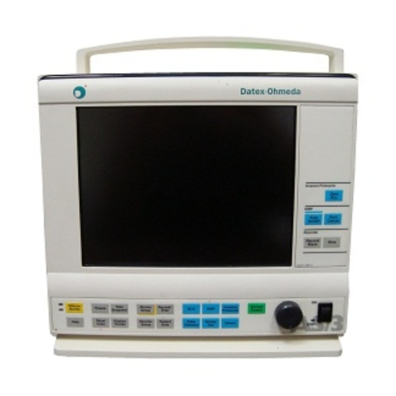
Page 23: Compact Monitor Connections
General Service Guide 3.3.1 Compact Monitor connections Figure 7 AS/3 Compact Monitor Connections Dust filter Recorder (optional) Connector for Remote Controller, Anesthesia Keyboard (K-ARK) and Bar Code Reader Potential equalization Mains power inlet Network connectors on B-NET/B-CMNET (optional) Device plate with voltage information... -
Page 24: Rear Panel Connectors
Datex-Ohmeda AS/3 Compact Monitor, CS/3 Compact Monitor 3.3.2 Rear panel connectors Figure 8 Rear Panel with Memory, CPU and UPINET Boards Software Cartridge, on CPU board, B-CPU2 or B-CPU3, or Software Card drive and lid for back plate on B-CMCPU4, connector on B-CMCPU4 is reserved for future use (not in figure). -
Page 25: Connection To Mains
The power cord may only be connected to a three-wire, grounded, hospital grade receptacle. 3.3.4 Connection to Network To connect your monitor to Datex-Ohmeda Network, make sure you have a network board B-NET or B-UPINET installed. Use the Monitor-Network cable to connect the monitor to the network. -
Page 26: Replacing The Cpu Board, B-Cmcpu4
Datex-Ohmeda AS/3 Compact Monitor, CS/3 Compact Monitor 3.3.6 Replacing the CPU Board, B-CMCPU4 In case of service procedures (empty B-CMCPU4 and service software on PCMCIA card) refer the slot of CM Frame, CPUs and Softwares; Part II/1. Make sure that the power is turned off on the Compact Monitor and unplug the power cord. -
Page 27: Performing Factory Reset
General Service Guide Remove the CPU board from the protective anti static packaging. Always hold the board by the edges and wear a wrist grounding strap. CAUTION The CPU Board comprises sensitive integrated circuits that can be damaged by an electrostatic discharge. -
Page 28: Replacing The Software Cartridge Of B-Cpu2/3
Datex-Ohmeda AS/3 Compact Monitor, CS/3 Compact Monitor 3.3.8 Replacing the Software Cartridge of B-CPU2/3 NOTE: All user settings will be lost after replacing the software cartridge. Make sure that the power is turned off on the Compact Monitor and unplug the power cord. -
Page 29: Replacing The Cpu Board, B-Cpu2/3
General Service Guide 3.3.9 Replacing the CPU Board, B-CPU2/3 Make sure that the power is turned off on the Compact Monitor and unplug the power cord. Press and hold the service reset button on the rear panel for at least five seconds until the service reset indicator LED is switched off. - Page 30 Datex-Ohmeda AS/3 Compact Monitor, CS/3 Compact Monitor Remove the software cartridge. Unscrew the screw holding the CPU Board in position and remove the board. Remove the CPU Board from the protective anti static packaging. Always hold the board by the edges and wear a wrist grounding strap.
-
Page 31: As/3 Memory Board, B-Cmmem Installation (W/ B-Cpu2/3)
General Service Guide 3.4 AS/3 Memory Board, B-CMMEM Installation (w/ B-CPU2/3) Make sure that the power is turned off on the Compact Monitor and unplug the Power Cord. Press and hold the Service Reset button on the rear panel for at least five seconds until the service reset indicator LED is switched off. - Page 32 Datex-Ohmeda AS/3 Compact Monitor, CS/3 Compact Monitor Unscrew the two nuts holding the side plates in position and remove the plates. Put the memory card collar in the place of the side plates. Unscrew the five screws holding the bottom plate in position and remove the plate.
- Page 33 General Service Guide Insert the connection board into the empty slot and firmly press the board in position. Place the memory board, the bottom plate and the cover plate in position. First, secure the memory board with the three screws in the sequence indicated. Then, secure the memory board, the bottom plate and the cover plate with the two screws (M3x25).
-
Page 34: As/3 Memory Board, B-Cmmem Installation (W/ B-Cmcpu4)
Datex-Ohmeda AS/3 Compact Monitor, CS/3 Compact Monitor 3.5 AS/3 Memory Board, B-CMMEM Installation (w/ B-CMCPU4) Make sure that the power is turned off on the Compact Monitor and unplug the Power Cord. Press and hold the Service Reset button on the rear panel for at least five seconds until the service reset indicator LED is switched off. - Page 35 General Service Guide Unscrew the two nuts holding the side plates in position and remove the plates. Put the memory card collar in the place of the side plates. Unscrew the screws holding the bottom plate in position and remove the plate. Remove the Memory Board, B-CMMEM, including the connection board and the memory board, from the protective anti static packaging.
- Page 36 Datex-Ohmeda AS/3 Compact Monitor, CS/3 Compact Monitor Insert the connection board into the empty slot and firmly press the board in position. Place the memory board, the bottom plate and the cover plate in position. First, secure the memory board with the three screws in the sequence indicated. Then, secure the memory board, the bottom plate and the cover plate with the two screws (M3x25).
-
Page 37: Network Board, B-Net Installation (W/ B-Cpu2/3)
General Service Guide 3.6 Network Board, B-NET Installation (w/ B-CPU2/3) Insert the Network Board, B-NET according to following procedure. Make sure that the power is turned off on the Compact Monitor is and unplug the Power Cord. Press and hold the Service Reset button on the rear panel for at least five seconds until the service reset indicator LED is switched off. - Page 38 Datex-Ohmeda AS/3 Compact Monitor, CS/3 Compact Monitor Unscrew the five screws holding the bottom plate in position and remove the plate. Unscrew the screw holding the cover plate in position and remove the plate. Remove the Network Board, B-NET from the protective anti static packaging. Always hold the board by the edges and wear a wrist grounding strap.
- Page 39 General Service Guide Loosen the two screws holding the EMC plate in position, remove the plate and tighten the screws. Insert the Network Board, B-NET into the empty slot and firmly press the board in position. Secure the board with the screw removed from the cover plate earlier. Replace the bottom plate and secure the plate with the five screws removed from the plate earlier.
-
Page 40: Network Board, B-Cmnet Installation (W/ B-Cmcpu4)
Datex-Ohmeda AS/3 Compact Monitor, CS/3 Compact Monitor 3.7 Network Board, B-CMNET Installation (w/ B-CMCPU4) Insert the Network Board, B-CMNET (B-CMNET differs from B-NET with mechanical changes) according to following procedure. Make sure that the power is turned off on the Compact Monitor is and unplug the Power Cord. - Page 41 General Service Guide Unscrew the screws holding the bottom plate in position and remove the plate. Remove the Network Board, B-CMNET from the protective anti static packaging. Always hold the board by the edges and wear a wrist grounding strap. CAUTION The Network Board, B-CMNET comprises sensitive integrated circuits that can be damaged by an electrostatic discharge.
-
Page 42: As/3 Upinet Board, B-Upinet Installation (W/ B-Cpu2/3)
Datex-Ohmeda AS/3 Compact Monitor, CS/3 Compact Monitor 3.8 AS/3 UPINET Board, B-UPINET Installation (w/ B-CPU2/3) Insert the B-UPINET Board according to following procedure. Make sure that the power is turned off on the Compact Monitor and unplug the Power Cord. - Page 43 General Service Guide Unscrew the two screws holding the software cartridge in position and remove the cartridge. Unscrew the three screws holding the UPI Board in position and remove the board. Remove the UPINET Board, B-UPINET from the protective antistatic packaging. Always hold the board by the edges and wear a wrist grounding strap.
- Page 44 Datex-Ohmeda AS/3 Compact Monitor, CS/3 Compact Monitor Insert the UPINET Board, B-UPINET into the empty slot and firmly press the board in position. Secure the board with the two screws removed from the UPI Board earlier. Attach the EMC gasket to the EMC cases on the UPINET Board so that the adhesive part of the gasket is against the cases.
-
Page 45: As/3 Upinet Board, B-Upinet Installation (W/ B-Cmcpu4)
General Service Guide 3.9 AS/3 UPINET Board, B-UPINET Installation (w/ B-CMCPU4) Insert the B-UPINET Board according to following procedure. Make sure that the power is turned off on the Compact Monitor and unplug the Power Cord. Press and hold the Service Reset button on the rear panel for at least five seconds until the service reset indicator LED is switched off. - Page 46 Datex-Ohmeda AS/3 Compact Monitor, CS/3 Compact Monitor Unscrew the three screws holding the UPI Board in position and remove the board. Remove the UPINET Board, B-UPINET from the protective antistatic packaging. Always hold the board by the edges and wear a wrist grounding strap.
-
Page 47: Compact Airway Modules, M-Xxxx
3.10 Compact Airway Modules, M-XXXX Airway modules of M-family (M-C etc.) are installed as any plug-in modules. Figure 10- Datex-Ohmeda Compact Airway Module 3.10.1 Sample Gas Exhaust When N O or volatile anesthetics are used, pollution of the operation room by these gases should be prevented. -
Page 48: Scavenging Through Reservoir
Datex-Ohmeda AS/3 Compact Monitor, CS/3 Compact Monitor 3.10.2 Scavenging Through Reservoir SAMPLE GAS OUT Figure 11 Scavenging through Ventilator Reservoir • Connect an exhaust line to the sample gas outlet on the module’s front panel. • Attach the other end of the line to the ventilator reservoir. Make sure that the reservoir tube diameter is at least 2-3 times larger than the exhaust line. -
Page 49: Returning Gas To Patient Circuit
3.12 Remote Controller, K-REMCO To connect a Remote Controller, K-REMCO to your Compact Monitor you need a Remote Controller- Compact Monitor Cable. For further information, please contact your authorized Datex-Ohmeda distributor. Document No. 896 623... -
Page 50: Bar Code Reader
3.13.2 Different Configurations The bar code reader comes from HP factory with factory default settings. These settings are slightly modified at Datex-Ohmeda factory to match Datex-Ohmeda applications. The following table shows the differences between the HP configuration and the Datex-Ohmeda configuration. - Page 51 General Service Guide Start the configuration (Default Wedge Mode). Begin with the header label (Header). Set the contents of the header to hhh. End the header (End of Characters). Clear the no-read message (No-Read Message is Empty). Select the interkey delay (Interkey Delay). Set the interkey delay to 12 s. The configuration of the bar code reader is shown by scanning the Show Configuration label.
-
Page 52: Troubleshooting
Datex-Ohmeda AS/3 Compact Monitor, CS/3 Compact Monitor 3.14 Troubleshooting If a problem occurs during the functional examination, check the components of the monitor according to the following troubleshooting chart. If the problem persists, please refer to the part II. TROUBLE... -
Page 53: Interfacing
You can interface external devices to the AS/3 and CS/3 monitor via B-UPI or B-UPINET Board and Interface Module (M-INT). For interfacing an intra-aortic balloon pump, ECG and pressure signals are available from the M-PT module. Via B-UPI or B-UPINET board you can interface: • Datex-Ohmeda monitors • AS/3 Anesthesia Delivery Unit • printers Via M-INT you can interface: •... -
Page 54: Interfacing Monitors Via Upi Board, B-Upi
The parameters transferred to the Compact Monitor are summarized in table 4-1. 4.1.1 Interconnection Datex-Ohmeda Monitors Use the UPI-Monitor Cable to connect Compact Monitor to Datex-Ohmeda monitors. Make sure that the power to both devices is turned off. Connect the 9 pin D-shaped connector to the X3 connector and the 44 pin D-shaped connector to the X2 connector on the UPI Board. -
Page 55: Setting The Interfacing Parameters
Press the Normal Screen key. 4.2 Interfacing with Datex-Ohmeda Monitors via UPINET Board, B-UPINET It is possible to interface Datex-Ohmeda monitors to the Compact Monitor via the UPINET Board, B- UPINET. The parameters transferred to the Compact Monitor are summarized in table 4-1. -
Page 56: Interfacing Monitors Via M-Int
Interface Module, M-INT. Interface Module, M-INT, has two serial and analog connectors (X7 and X8). The parameters transferred are summarized in tables 4-1 and 4-2. NOTE: Using the Interface Module , M-INT disables interfacing with Datex-Ohmeda monitors via the UPI/UPINET Board. -
Page 57: Connection To Critikon Dinamap 1846Sx, Abbott Oximetrix 3 And Baxter Explorer
Connect the mono connectors to the corresponding connectors on the other monitor. 4.4 Interfacing Datex-OhmedaAS/3 Anesthesia Delivery Unit It is possible to interface Datex-Ohmeda Anesthesia Delivery Unit to the Compact Monitor via the UPI Board. For further information, please contact your authorized Datex-Ohmeda distributor. -
Page 58: Interfacing Dräger Cicero And Cato
4.5 Interfacing Dräger Cicero and Cato It is possible to interface Dräger Cicero and Cato to the Compact Monitor via the Interface Module, M-INT. For further information, please contact your authorized Datex-Ohmeda distributor. WARNING Always make sure that the combination complies with the international safety standard IEC 60601-1-1 for medical electrical systems and with the requirements of local authorities. -
Page 59: Upi Board Output Signals
General Service Guide 4.8 UPI Board Output Signals The analog and digital connector X2 on the UPI Board, can be used to interface other devices to the Compact Monitor. Pin assignments are listed in table 4-3. WARNING Always make sure that the combination complies with the international safety standard IEC 60601-1-1 for medical electrical systems and with the requirements of local authorities. -
Page 60: Analog Outputs
Datex-Ohmeda AS/3 Compact Monitor, CS/3 Compact Monitor Signal Analog output, Ch 3 Analog input, Ch 1 Analog output, Ch 2 Analog output, Ch 0 Digital input 4 Analog input Ch 2 Digital input 5 Analog output, Ch 6 Analog output Ch 7... -
Page 61: Setting The Analog Output Signals
General Service Guide >40, SpO >60, SpO >80 (beat-to-beat, display value, 10 s average): The original scale 40- 100% (SpO >40), 60-100% (SpO >60) or 80-100% (SpO >80) is scaled between -5 and +5 volts. : The original scale 0%...10% is scaled between 0 and +5 volts. Values greater than 10% are set to 10%. -
Page 62: Pressure Temp Module, M-Pt Output Signals
Datex-Ohmeda AS/3 Compact Monitor, CS/3 Compact Monitor 4.9 Pressure Temp Module, M-PT Output Signals The signal output connector on the Pressure Temp Module, M-PT can be used to interface some models of IABPs to the Anesthesia Monitor/Critical Care Monitor. The pin assignments are illustrated in table 4-12. -
Page 63: Functional Check
Disconnect the mains power cord and press the service reset- switch until the LED next to it turns off. • If the monitor is connected to the Datex-Ohmeda network, disconnect the Mon-Net cable from the monitor’s Network extension cable. If the Memory Board, B-CMNET or the Memory Module, M-MEM, is connected, remove any memory cards. - Page 64 Datex-Ohmeda AS/3 CM and CS/3 CMC General Check the external parts: − All the four rubber pads under the monitor are in place. − All the stickers are intact. − The LCD screen is intact. − The ComWheel cover is intact and attached properly.
- Page 65 General Service Guide Compact Airway Module, M-CXXXXX Disconnect the module and check external parts: − the front cover and the front panel stickers are intact − all connectors are intact and are attached properly − the D-fend latch moves properly −...
-
Page 66: Functional Inspection
Datex-Ohmeda AS/3 CM and CS/3 CMC 5.3 Functional Inspection Start up Connect the mains power cord to the Frame. Check that the stand-by LED is lit . Check that the fans start running. Turn the monitor on. Check that the monitor starts up properly, i.e. - Page 67 General Service Guide - Responses -100 - Stim. Frequency - 1.1Hz - Stim. Intensity - 90 dB - Sweep length - 100 ms Record/ Print - Record Waveforms - Waveform 1 - ECG1 - Waveform 2 - P1 - Waveform 3 - P2 - ECG Setup - HR Source - AUTO Invasive Pressures - P1 ‘ART’...
- Page 68 Datex-Ohmeda AS/3 CM and CS/3 CMC LCD display Check that the picture on the LCD display screen is clear and stable. Monitor Setup key Press and select: Install/Service (password 16-4-34)- Service (password 26-23-8) - Display Select Colors and check that all colors are clear.
- Page 69 General Service Guide Compact Monitor Frame Check that the clock on the screen shows correct time. If necessary adjust the time: Monitor Setup - Time and Date NOTE: You cannot change the monitor’s time after a case has started. This prevents losing the trend data.
- Page 70 Datex-Ohmeda AS/3 CM and CS/3 CMC Compact Airway Module Check that the fan is running. Select the pressure and the flow waveform on the monitor screen: Monitor Setup - Screen 1 Setup - Waveform Fields - Field 5 - Paw...
- Page 71 General Service Guide Check that the ‘Amb-Work’ value in the service menu is within the following range: M-COVX/CAiOVX Others Amb-Work (mmHg) 70-115 40-75 Block the tip of the sampling line with your finger and check that the message ‘Sample line blocked’...
- Page 72 Datex-Ohmeda AS/3 CM and CS/3 CMC Hemodynamic Modules ECG measurement Enter the ESTP : ECG service menu: Monitor Setup - Install/Service (password 16-4-34) - Service (password 26-23-8) - Parameters - ESTP : ECG Check that the ‘Timeouts’, ‘Bad checksums’ and ‘Bad c-s by mod’ values are not increasing faster than by 50 per second.
- Page 73 General Service Guide The configuration in use is shown next to the ‘Configuration’ text and it may be either STP, ST or TP. If necessary change the protection mode, or the module configuration on the Calibrations - menu. For modules w/ invasive blood pressure measurement Check the module membrane keys that are related to the InvBP or temperature measurement: Press each of the keys for at least one second.
- Page 74 Datex-Ohmeda AS/3 CM and CS/3 CMC Attach an adult NIBP cuff onto your arm and perform one NIBP measurement. Check the module identifies the cuff, i.e. the text ‘Adult’ appears in the NIBP digit field for a short time. Check that the module gives a reasonable measured result.
- Page 75 General Service Guide Check that the module configuration is set correctly. The configuration in use is displayed next to the ‘Configuration’ text in the service menu and it can be either BP or PT. If necessary, change the configuration in the Calibrations -menu. For modules w/ temperature measurement Check that the protection for temperature calibration is on.
- Page 76 Datex-Ohmeda AS/3 CM and CS/3 CMC Invasive blood pressure measurement Zero P4 Check the module membrane key. Press the key for at least one second. Check that the key being pressed is identified, i.e. the information on the service menu under ‘Button’ - ‘P4’ changes from OFF to ON.
- Page 77 General Service Guide Press each membrane key on the module front panel for at least one second. Check that the key being pressed is identified in the menu, i.e. text OFF changes to ON. Attach an adult NIBP cuff onto your arm and perform one NIBP measurement. Check the module identifies the cuff, i.e.
- Page 78 Datex-Ohmeda AS/3 CM and CS/3 CMC Check that all three error indicators, ‘MP-203(4) Error’, ‘QUART Error’ and ‘I/O Error’ show Connect a Nellcor SpO finger probe to the module. Check that the message ‘Pulse search’ is shown and the corresponding status information in the menu is active. Check that the shown message changes to ‘Check probe’...
- Page 79 General Service Guide Memory Board, B-CMMEM/ Memory Module, M-MEM Enter the MemCards service menu: Monitor Setup - Install/Service (password 16-4-34) - Service (password 26-23-8) - Frame - MemCards Check that the module is recognized properly, i.e. ‘Present’ and ‘Active’ state YES. Check that the Memory board memories and the PCMCIA controller have passed the tests.
- Page 80 Check that the Mon-Net cable connector and the Identification plug are clean and intact, then connect them to the Network Board. Check that the monitor connects to the Datex-Ohmeda Network, i.e. the network symbol appears under the clock on the upper right-hand corner of the screen. Also a message regarding the connected Datex-Ohmeda Central should appear in the message field on the screen.
- Page 81 General Service Guide Check the communication to the network by checking the states of the Network Board rear panel LEDs: TxD (Green); should blink intermittently RxD (Yellow); should blink intermittently L (Green); should be lit continuously C (Yellow); should be lit continuously NOTE: The B-UPINET board doesn’t have LEDs.
-
Page 82: General Troubleshooting
Datex-Ohmeda AS/3 CM and CS/3 CMC GENERAL TROUBLESHOOTING Monitor not functioning On/STBY switch ’ON’ Display connected? Connect and check Keyboard connected? Power cord Disconnect and reconnect the power cord connected? The power supply unit Connect power cord was shut down by instant over voltage in the mains. - Page 83 APPENDIX A, Functional check form, AS/3 CM and CS/3 CMC APPENDIX A Document No. 896 623...
- Page 84 Datex-Ohmeda AS/3 CM and CS/3 CMC Document No. 896 623...
-
Page 85: Functional Check Form
APPENDIX A, Functional check form, AS/3 CM and CS/3 CMC FUNCTIONAL CHECK FORM Datex-Ohmeda AS/3 Compact Monitor, CS/3 Compact Monitor Customer Service Service engineer Date Monitor installation F-CM OK = Test OK N.A. = Test not applicable Fail = Test Failed... - Page 86 Datex-Ohmeda AS/3 CM and CS/3 CMC Tonometry Module N.A. Fail 6. External parts Notes Other plug in modules and EEG Headbox, N-EEG N.A. Fail N.A. Fail 7. External parts 8. N-EEG Notes Functional inspection Start up N.A. Fail N.A. Fail 9.
- Page 87 APPENDIX A, Functional check form, AS/3 CM and CS/3 CMC Notes Remote Controller N.A. Fail 18. ComWheel Notes Compact Monitor Frame N.A. Fail N.A. Fail 19. Real-time clock 20. Loudspeaker 21. Battery status 22. Battery operation Notes Compact Airway Module General N.A.
- Page 88 Datex-Ohmeda AS/3 CM and CS/3 CMC Hemodynamic Modules, M-NE(12)STPR etc. Module: ECG measurement N.A. Fail N.A. Fail 34. Test with TEMP plugs 35. Membrane key 36. Power frequency RESP measurement N.A. Fail N.A. Fail 37. Recognition TEMP measurement N.A. Fail N.A.
- Page 89 APPENDIX A, Functional check form, AS/3 CM and CS/3 CMC PP module N.A. Fail N.A. Fail 52. Communication and 53. Membrane keys memories Notes COP/COPSv module N.A. Fail 54. Communication and memories InvBP measurement 55. Membrane key measurement 56. Service menu values C.O.
- Page 90 Datex-Ohmeda AS/3 CM and CS/3 CMC NSAT Module N.A. Fail N.A. Fail 64. Communication and 65. SpO probe status memories 66. Error status 67. SpO probe detection 68. Test measurement Notes Recorder unit/ Module N.A. Fail N.A. Fail 69. Recorder messages 70.
- Page 91 APPENDIX A, Functional check form, AS/3 CM and CS/3 CMC General N.A. Fail 82. Final cleaning Notes Notes Signature A - 7(7) Document No. 896 623...
Need help?
Do you have a question about the AS/3 Compact Monitor and is the answer not in the manual?
Questions and answers