Table of Contents
Advertisement
Quick Links
Advertisement
Chapters
Table of Contents
Troubleshooting

Related Manuals for Datex-Ohmeda Aestiva 7900 SmartVent


Summary of Contents for Datex-Ohmeda Aestiva 7900 SmartVent
- Page 1 Aestiva/5 7900 Anesthesia Ventilator Technical Reference Manual...
- Page 2 Aestiva 7900 Anesthesia Ventilator Datex-Ohmeda products have unit serial numbers with coded logic which indicates a product group code, the year of manufacture and a sequential unit number for identification. AAA A 12345 This alpha character indicates the year of product manufacture and when the serial number was assigned;...
- Page 3 Software Revisions 1.X, 3.X, and 4.X This document is not to be reproduced in any manner, nor are the contents to be disclosed to anyone, without the express authorization of the product service department, Datex-Ohmeda, Ohmeda Drive, PO Box 7550, Madison, Wisconsin, 53707.
-
Page 4: Important
The information contained in this service manual pertains only to those models of products which are marketed by Datex-Ohmeda as of the effective date of this manual or the latest revision thereof. This service manual was prepared for exclusive use by Datex-Ohmeda service personnel in light of their training and experience as well as the availability to them of parts, proper tools and test equipment. -
Page 5: Table Of Contents
Table of Contents Important ..............ii Technical Competence . - Page 6 Table of Contents 2 Theory of Operation 2.1 General description ............2-2 2.2 Aestiva 7900 Ventilator features .
- Page 7 Table of Contents 4a Tests and Calibration — Software Revision 4.X 4a.1 Self tests ............. . .4a-3 4a.2 Service Mode Confirmation menu .
- Page 8 Table of Contents 4b.4 Diagnostic Tests ............4b-7 4b.4.1 Test CPU .
- Page 9 Table of Contents 5 Troubleshooting 5.1 Troubleshooting instructions ..........5-2 5.2 System Error Log .
- Page 10 Table of Contents 7.8 Flow control valve 7-17 7.9 Gas inlet valve 7-18 7.10 Mechanical Overpressure Valve (MOPV assembly) 7-20 7.10.1 To service the original MOPV assembly: 7-20 7.10.2 To service the MOPV assembly with the molded housing: 7-22 7.11 Drive gas check valve assembly 7-23 8 Illustrated Parts 8.1 Special instructions 8-2 8.2 Service tools 8-2...
-
Page 11: Introduction
1 Introduction In this section 1.1 What this manual includes ..........1-2 1.1.1 Software versions . -
Page 12: What This Manual Includes
1 Introduction 1.1 What this manual includes This manual covers the service information for the Aestiva 7900 SmartVent Anesthesia Ventilator which is an integral component in the Aestiva Anesthesia Machine. The Aestiva Anesthesia Machine has its own service manual (Stock Number 1006-0452-000). -
Page 13: Standard Service Procedures
• Use the Anesthesia Machine service manual (1006-0452-000) for all other components of the Aestiva Anesthesia Machine. 1.2.3 Ventilator Service calibration functions let Datex-Ohmeda trained users and Datex- Ohmeda service personnel perform ventilator setup functions, tests, tests calibration and measurements from the front panel display. -
Page 14: Symbols Used In The Manual Or On The Equipment
Cautions tell about a condition that can cause damage to the equipment. Read and follow all warnings and cautions. Other symbols replace words on the equipment or in Datex-Ohmeda manuals. No one device or manual uses all of the symbols. These symbols include:... - Page 15 1 Introduction Variability Read top of float. Variability in steps Vacuum inlet This way up Suction bottle outlet Lamp, lighting, illumination Cylinder Lock Isolation transformer Unlock Linkage system Close drain Risk of Explosion. Open drain (remove liquid) Low pressure leak test 134°C Autoclavable Mechanical ventilation...
- Page 16 1 Introduction Absorber on. The primary regulator is set to < 345 kPa pressure less than 345 kPa (50 psi). Absorber off (CO Bypass active). The primary regulator is set to < 414 kPa pressure less than 414 kPa (60 psi). Systems with this mark agree with the European Council Directive European Union Representative.
-
Page 17: Theory Of Operation
2 Theory of Operation In this section This section provides functional descriptions and theory of operation for the major components of the Aestiva 7900 Ventilator. 2.1 General description ............2-2 2.2 Aestiva 7900 Ventilator features . -
Page 18: General Description
2 Theory of Operation 2.1 General description The Aestiva 7900 Ventilator is a microprocessor based, electronically- controlled, pneumatically-driven ventilator with built in monitoring systems for inspired oxygen, airway pressure and exhaled volume. The ventilator is designed to be used as a medical device assisting in the delivery of anesthesia and is part of the Aestiva Anesthesia Machine. -
Page 19: Safety Features
2 Theory of Operation 2.2.1 Safety features • Dual redundant airway overpressure protection, linked to Pmax setting. • Volume over-delivery limits and protection. • Proprietary hose connections and fixed manifolds. • 10 VA electrical power limiting to potential oxygen enriched environment. •... -
Page 20: Ventilator Control Electronics
2 Theory of Operation 2.3.1 Ventilator control The ventilator control electronics is found in the electrical enclosure of the Aestiva machine behind the AC Inlet module. electronics In the original Aestiva machines, the power supply and the CPU are on separate boards, as shown in Figure 2-2. - Page 21 2 Theory of Operation In current Aestiva machines, the regulated power supplies and the CPU are included on a single board (Integrated CPU Board), as shown in Figure 2-3. A universal power supply is used to convert AC to DC that feeds into the power supply circuits of the integrated CPU board.
-
Page 22: Control Panel And Display
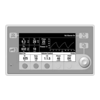
2 Theory of Operation 2.3.2 Control panel and The control panel on the Aestiva 7900 Ventilator is either outboard (on an arm) or on a hinge to fold flat against the machine (depending on the option display ordered) and is made to permit you to grip the panel and push the buttons with your thumbs. -
Page 23: Sensor Interface Board (Sib)
2 Theory of Operation 2.3.3 Sensor Interface A Sensor Interface Board (SIB) serves as the interface between the ventilator CPU board and the breathing circuit sensors. Board (SIB) The SIB processes signals from the: • Inspiratory and expiratory flow transducers •... -
Page 24: Electrical
2 Theory of Operation 2.4 Electrical 2.4.1 Electrical The original (non-integrated) Aestiva 7900 Ventilator electronic/electrical subassemblies or modules include: (original) • Power entry toroid • Power supply board • CPU board • Display and front panel assembly • Sensor interface board •... -
Page 25: Electrical (Integrated)
2 Theory of Operation 2.4.2 Electrical The integrated Aestiva 7900 Ventilator electronic/electrical subassemblies or modules include: (integrated) • Universal power supply (AC to DC converter) • CPU board (with power supply and digital circuits) • Display and front panel assembly •... -
Page 26: Power Supply (Original)
2 Theory of Operation 2.4.3 Power supply The power supply performs seven functions: (original) • AC to DC converter • DC to DC step-down converter • Battery charger • Multiple output DC regulator • Battery charge/discharge current monitor • Battery voltage monitor •... -
Page 27: Power Supply (Integrated Cpu)
2 Theory of Operation 2.4.4 Power supply Aestiva machines with an integrated CPU board use a universal power supply for AC to DC conversion. The remainder of the power supply functions are (integrated CPU) derived in the power supply circuits on the integrated CPU: •... -
Page 28: Sealed Lead Acid Battery
2 Theory of Operation 2.4.5 Sealed lead acid A sealed lead acid battery supplies battery backup for the Aestiva 7900 Ventilator. The Aestiva 7900 Ventilator is not a portable unit. Batteries for the battery ventilator are used as back up power in case of a power failure. Thus the battery is in a float charge state most of the time. -
Page 29: Cpu Assembly
2 Theory of Operation 2.4.6 CPU assembly The CPU assembly contains all of the major circuit functions necessary to control ventilator operation. In the original Aestiva 7900 machines, these functions are on a separate CPU board. For current machines, they are part of the digital circuits section of the integrated CPU board. - Page 30 2 Theory of Operation System clock An external 32.768 kHz crystal is used with the internal clock synthesizer to generate a 24.12 MHz system clock. Periodic interrupt timer The periodic interrupt timer is the time base for the Real Time Operating System.
- Page 31 2 Theory of Operation Program memory Flash memory Two 512K x 8 Flash memory devices are used. This memory contains the real time operating system (RTOS) and software code. The Flash memory devices are socketed. System RAM This memory consists of two 128 K x 16 CMOS static RAMs with on-board expansion capability to 512K x 16 SRAMs.
- Page 32 2 Theory of Operation A system reset will occur between 62.5 msec and 250 msec if no legal toggle addresses occur by that time. Multiple level 7 interrupts will occur prior to a reset. The output of this watchdog is connected to IRQ7 on the 68340 processor.
- Page 33 2 Theory of Operation Analog to digital converter A 24 channel multiplexer and buffer amplifier precedes the A/D converter. The manifold pressure, patient pressure, inspiratory flow and expiratory flow System signal inputs to the multiplexer are filtered with an antialiasing filter. Other inputs are filtered by low pass filters.
- Page 34 2 Theory of Operation Flow valve control The flow valve control circuit consists of a D/A converter and a voltage to current conversion circuit. D/A conversion The D/A conversion for the flow valve drive circuit is based around the MAX530 12-Bit DAC. The output of the DAC is fed to an input of the A/D converter multiplexer allowing the microprocessor to monitor the DAC output.
- Page 35 2 Theory of Operation Front panel display interface All signals to and from the Front Panel are protected from ESD through the use of transient suppression devices and appropriate filtering. All of these signals are routed through a single connector from the microcontroller board to the front panel assembly.
-
Page 36: Sensor Interface Board (Sib)
2 Theory of Operation 2.4.7 Sensor Interface The breathing circuit Sensor Interface Board, (SIB), is the connection between the flow transducers, patient airway pressure transducer, manifold pressure Board (SIB) transducer, oxygen sensor, and ventilator control module. It also passes different switch functions through to the ventilator control module. These switches are used to show the position of covers, breathing circuit modules and pneumatic controls in the breathing circuit. - Page 37 2 Theory of Operation Functional description Power supply regulators The SIB power supply is a 10VA limited +12V to +15V supply from the Aestiva 7900 Ventilator CPU board. The supply is filtered at the SIB. There are two regulators on the SIB that are supplied by the 12V to 15V supply.
- Page 38 2 Theory of Operation Drive pressure limit switch The drive pressure limit switch, found on the SIB, is used to monitor the drive gas pressure from the ventilator pneumatic engine. This normally closed switch signal is sent to the Aestiva 7900 Ventilator CPU board. The switch will open if the drive gas pressure is more than 104 +5/-4 cm H 2 O.
-
Page 39: Mechanical Subsystems
2 Theory of Operation 2.5 Mechanical subsystems Refer to the system connection block diagram in Section 9 of the Aestiva Anesthesia Machine Service Manual for the complete pneumatic/mechanical subsystem. The mechanical subsystem includes: Pneumatic Engine • Drive gas inlet filter •... -
Page 40: Gas Inlet Valve (Giv)
2 Theory of Operation 2.5.2 Gas Inlet Valve During normal operation the Gas Inlet Valve (GIV) is open to let supply gas flow to the ventilator manifold. This valve provides a shutoff of the supply gas to the (GIV) ventilator when the ventilator is not in use. This valve also shuts off supply gas to the ventilator under failure conditions detected by the CPU or over-pressure switch. -
Page 41: Drive Gas Check Valve (Dgcv)
2 Theory of Operation BELLOWS PRESSURE TO MANIFOLD BREATHING CIRCUIT RELIEF PRESSURE FLOW TRANSDUCER TO DRIVE PRESSURE LIMIT SWITCH 100 cm H 2 O ATMOSPHERE EXHALATION VALVE FREE BREATHING CHECK VALVE MECHANICAL OVERPRESSURE RELIEF 110 cm H 2 O TEST 5 MICRON POINT INLINE INLET... -
Page 42: Exhalation Valve
2 Theory of Operation 2.5.6 Exhalation valve The autoclavable exhalation valve manifold contains an elastomeric diaphragm that is used along with the flow valve to control the pressures in the breathing circuit. The manifold contains two male ports on the bottom for: •... -
Page 43: Free Breathing Valve
2 Theory of Operation 2.5.9 Free breathing The free breathing valve helps assure the patient can spontaneously breathe. The ventilator is programmed to supply a specified number of breaths per valve minute to the patient. If, in between one of these programmed cycles, the patient needs a breath (spontaneous), the free breathing valve permits the patient to inhale. - Page 44 Notes 2-28 05/04 1006-0453-000...
-
Page 45: Post-Service Checkout
3 Post-Service Checkout In this section 3.1 Post-service checkout ............3-2 3.1.1 Test the Aestiva 7900 Ventilator . -
Page 46: Test The Aestiva 7900 Ventilator
3 Post-Service Checkout 3.1 Post-service checkout After servicing the Aestiva 7900 Ventilator, run the service menu tests that are pertinent to the components replaced. Perform calibration on flow sensors, pressure sensitivity, flow valve and bleed resistor. Then you must complete the checkout procedure for the entire machine: •... -
Page 47: Tests And Calibration - Software Revision
4a Tests and Calibration — Software Revision WARNING Post-Service Checkout is required after you complete this section. You must perform Section 3.1 Post-service checkout after performing any maintenance, service or repair. Failure to do so may result in patient injury. CAUTION Section 4a should only be used with version 4.X software. - Page 48 4a.3.11 Test Serial Ports ..........4a-20 4a.3.12 Breathing System Leak Test .
-
Page 49: 4A.1 Self Tests
4a Tests and Calibration 4.X Software 4a.1 Self tests The Aestiva 7900 Ventilator software includes self tests that determine whether or not the operating software is functioning properly and whether or not the electronic circuits on the circuit boards are functional. The self tests include: •... -
Page 50: 4A.2 Service Mode Confirmation Menu
4a Tests and Calibration 4.X Software 4a.2 Service Mode Confirmation menu The service calibration mode tests and/or calibrates hardware necessary to prepare a ventilator manufactured for shipment and to service a ventilator in the field. There are two ways to enter the service mode: •... -
Page 51: 4A.3 Main Menu - Service Mode
4a Tests and Calibration 4.X Software 4a.3 Main Menu - Service Mode The service mode is entered from the service confirmation menu. Select “Service Mode” and push the adjustment knob. The Service Mode main menu allows navigation to the individual menus for alarm or error logs, calibrations, system configurations, diagnostic tests and tools, and user selected defaults. -
Page 52: 4A.3.1 Alarm Log
4a Tests and Calibration 4.X Software 4a.3.1 Alarm Log The Alarm Log displays up to 10 of the most current alarm messages that have been logged. Each log entry shows: • Bootup Count - number (the bootup count is incremented each time the machine is turned on). -
Page 53: 4A.3.2 Error Log
4a Tests and Calibration 4.X Software 4a.3.2 Error Log There are two special types of alarms: • Minimum monitoring alarms that stop mechanical ventilation • Minimum system shutdown alarms that stop mechanical ventilation and monitoring. An alarm message that results from these special types of alarms is considered an error alarm. -
Page 54: 4A.3.3 System Configuration
4a Tests and Calibration 4.X Software 4a.3.3 System The System Configuration menu includes settings that are tailored to the specific machine. Configuration Figure 4-5 • Calibrations/System Configuration menu 4a.3.3.1 Altitude The accuracy of some of the ventilator measurements is altitude sensitive. To ensure the specified accuracy, the altitude setting should be set to the specific altitude where each machine is located. - Page 55 4a Tests and Calibration 4.X Software Figure 4-7 • Drive Gas menu item 4a.3.3.3 Heliox Mode Aestiva machines can be configured to deliver Heliox. These machines should have the Heliox Mode “On”. With the Heliox Mode On, the operator can choose to turn the Heliox On or Off in the Setup/Calibration menu.
- Page 56 4a Tests and Calibration 4.X Software Figure 4-9 • VE Alarm Limits menu item 4a.3.3.5 Language The text shown in the normal mode of operation is language sensitive. However, the majority of service confirmation and calibration modes are shown in English. The other language choices are shown in specific language text with the exception of Japanese which is shown in English.
- Page 57 4a Tests and Calibration 4.X Software 4a.3.4.6 Optimal Screen The Screen Contrast menu is used to select the display brightness. The values range from 1 to 10, with 10 having the most screen contrast. Contrast Figure 4-11 • Optimal Screen Contrast menu item 1006-0453-000 05/04 4a-11...
-
Page 58: 4A.3.4 User Select Defaults
4a Tests and Calibration 4.X Software 4a.3.4 User Select The User Select Defaults menu determines the control settings used by the system at power up. Defaults Settings related to optional ventilation modes will only appear in the User Select Defaults if the optional modes are active. These settings include: •... - Page 59 4a Tests and Calibration 4.X Software The following parameters may be set in User Select Defaults: • Ventilation Mode • Tidal Volume (V • Inspired Pressure (Pinspired) • Respiratory Rate • I:E Ratio • Pressure Limit (Plimit) • Inspiratory Pause •...
-
Page 60: 4A.3.5 Test Cpu And Memory
4a Tests and Calibration 4.X Software 4a.3.5 Test CPU and The software checks the CPU, ROM, RAM, and display RAM through this menu. When Start Test is selected the series of tests begins to run. When each Memory test is running, the word “Testing. . .” appears after the test name. Figure 4-14 •... -
Page 61: 4A.3.6 Test Eeprom
4a Tests and Calibration 4.X Software 4a.3.6 Test EEPROM The software tests all the EEPROM memory via a bit pattern test. It writes a certain pattern to a block of memory and then reads back that block of memory. If the bit pattern that was written is not the same bit pattern that it reads back, the test fails. -
Page 62: 4A.3.7 Test Giv
4a Tests and Calibration 4.X Software 4a.3.7 Test GIV To test the GIV (gas inlet valve) the software first closes the GIV. It reads the A/D channel for the GIV. If the A/D channel for the GIV does not read closed, the test fails;... -
Page 63: 4A.3.8 Test Flow Valve
4a Tests and Calibration 4.X Software 4a.3.8 Test Flow Valve To test the flow valve the software starts by closing the flow valve. It then opens the flow valve in increments until the flow valve is completely open. At each of the settings of the flow valve the A/D (Analog/Digital) channel for Flow DAC (Digital to Analog Converter) Feedback and Flow Current Sense will be read. -
Page 64: 4A.3.9 Test Drive Pressure Limit Switch
4a Tests and Calibration 4.X Software 4a.3.9 Test Drive The software tests the pressure limit switch to make sure that it trips at the correct manifold over pressure. The software opens the flow valve to a value Pressure Limit Switch where pressure continues to increase. -
Page 65: 4A.3.10 Test 5V Fail Alarm
4a Tests and Calibration 4.X Software 4a.3.10 Test 5V Fail A 5-Volt supply (VDD) is used to power the digital circuits throughout the ventilator. Alarm The 5-Volt supply (VDD) is derived in the power section of the control board. It is used to power the digital circuits throughout the ventilator. -
Page 66: 4A.3.11 Test Serial Ports
4a Tests and Calibration 4.X Software 4a.3.11 Test Serial Ports Two serial port tests may be done: • Public Port Test (Com 2) - requires pins 6 and 13 of the serial connector to be jumpered. • Proprietary Port Test (Com 1)- requires pins 2 and 3 of the serial connector to be jumpered. -
Page 67: 4A.3.12 Breathing System Leak Test
4a Tests and Calibration 4.X Software 4a.3.12 Breathing You can estimate how much of a leak there is in the ventilator portion of the breathing system by closing the patient circuit, inflating the bellows, and System Leak Test observing how quickly they fall on their own weight (part of the machine checkout procedure). -
Page 68: 4A.3.13 Display A/D Channels
4a Tests and Calibration 4.X Software 4a.3.13 Display A/D The software displays the A/D values for each of the A/D channels. Channels Figure 4-23 • Page 1 of Display A/D Channels menu Figure 4-24 • Page 2 of Display A/D Channels menu Remarks This selection displays a listing of A/D Channels which are at various values depending upon the set parameters. - Page 69 4a Tests and Calibration 4.X Software Table 4a-1 A/D Channels A/D Channel Displayed Range Special Instructions Counts Actual Range 1800-2300 Near Zero L/min -120 to 120 L/min Zero Offset Reading (nominal 2050 Inspiratory Flow Counts) 1800-2300 Near Zero L/min -120 to 120 L/min Zero Offset Reading (nominal 2050 Expiratory Flow Counts)
-
Page 70: 4A.3.14 Display Discrete I/O Signals
4a Tests and Calibration 4.X Software 4a.3.14 Display Discrete The Discrete I/O Signals menu displays discrete binary signals associated with machine switch positions. I/O Signals There are several types of switches in the Aestiva machine: • some switches are mechanically operated •... -
Page 71: 4A.3.15 Display Battery Status
4a Tests and Calibration 4.X Software 4a.3.15 Display Battery The software displays the battery charge status. This checks the battery charge current. Status N N N N o o o o t t t t e e e e : : : : A negative current value means the battery is charging. B B B B a a a a t t t t t t t t e e e e r r r r y y y y S S S S t t t t a a a a t t t t u u u u s s s s V V V V a a a a l l l l u u u u e e e e s s s s D D D D i i i i s s s s p p p p l l l l a a a a y y y y e e e e d d d d On Battery... -
Page 72: 4A.3.16 Test Panel Switches
4a Tests and Calibration 4.X Software 4a.3.16 Test Panel In the Test Panel Switches menu the software is set up to receive keyboard button presses and rotary encoder turns. Switches Press each button and turn the encoder one full turn in both directions. When a button is pressed and held, the icon on the screen next to the button will contain an “x”. -
Page 73: 4A.3.17 Flow Valve Test Tool
4a Tests and Calibration 4.X Software 4a.3.17 Flow Valve Test The Flow Valve Test Tool is available for test and troubleshooting purposes only. It allows you to manually control the flow valve setting from 0 (closed) to Tool 120 LPM, in 1 LPM increments, and observe key pressure and flow measurements on the same screen. -
Page 74: 4A.3.18 Adjust Drive Gas Regulator
4a Tests and Calibration 4.X Software 4a.3.18 Adjust Drive Gas The Adjust Drive Gas Regulator procedure establishes the required flow rate through the drive gas regulator for proper calibration. Regulator Figure 4-29 • Adjust Drive Gas Regulator menu Remarks The drive gas regulator should provide a constant gas input pressure of 172 kPa (25 psi). -
Page 75: 4A.3.19 O2 Calibrations
4a Tests and Calibration 4.X Software 4a.3.19 O2 Calibrations The O2 Calibrations take into account the altitude setting. Before starting the calibrations, ensure that the altitude setting (in Calibrations/System Configuration) is set to the appropriate altitude for the machine location. Note: a circle module is required for all calibrations. -
Page 76: 4A.3.20 Calibrate Flow Sensors
4a Tests and Calibration 4.X Software 4a.3.20 Calibrate Flow The software calibrates the inspiratory flow, expiratory flow, airway pressure and manifold pressure transducers for zero flow/pressure offset voltage. It Sensors does so by reading the A/D values for inspiratory flow, expiratory flow, airway pressure and manifold pressure when the flow sensor module has been disconnected from the bulkhead connector. -
Page 77: 4A.3.21 Pressure Sensitivity
4a Tests and Calibration 4.X Software 4a.3.21 Pressure The software prompts the user to perform the procedure to calibrate the pressure sensitivity. This calibration is not an automated calibration. It Sensitivity prompts the user to follow a set of procedural steps to perform the calibration. -
Page 78: 4A.3.22 Calibrate Flow Valve
4a Tests and Calibration 4.X Software 3. Adjust the APL to read 20 cm H O on the gauge. The flows may jump briefly, but should stabilize to read between +0.5 and -0.5 LPM. 4. Adjust the APL to read 40 cm H O on the gauge. -
Page 79: 4A.3.23 Bleed Resistor Calibration
4a Tests and Calibration 4.X Software 4a.3.23 Bleed Resistor The software calibrates the bleed resistor as described below. Other than the setup procedure, this calibration is completely automated. Calibration Figure 4-35 • Bleed Resistor Calibration menu Software procedure The software performs the calibration as follows: 1. -
Page 80: 4A.3.24 Service Calibrations Required
4a Tests and Calibration 4.X Software 4a.3.24 Service The Schedule Service Calibrations menu lists which setting or calibration must be performed when the “Service Calibration ” alarm appears in Calibrations Required normal operation. After the setting or calibration is properly completed, the text for that setting or calibration is removed from the list. - Page 81 4a Tests and Calibration 4.X Software Figure 4-38 • Service Calibration full menu 1006-0453-000 05/04 4a-35...
- Page 82 Notes 4a-36 05/04 1006-0453-000...
- Page 83 4b Tests and Calibration — Software Revisions 1.X and 3.X w w w w WARNING Post-Service Checkout is required after you complete this section. You must perform Section 3.1 Post-service checkout after performing any maintenance, service or repair. Failure to do so may result in patient injury. CAUTION Section 4b should only be used with versions 1.X and 3.X software.
- Page 84 4b.4 Diagnostic Tests ............4b-7 4b.4.1 Test CPU .
-
Page 85: 4B.1 Self Tests
4b Tests and Calibration 1.X/3.X Software 4b.1 Self tests The Aestiva 7900 Ventilator software includes self tests that determine whether or not the operating software is functioning properly and whether or not the electronic circuits on the circuit boards are functional. The self tests include: •... -
Page 86: 4B.2 Service Mode Confirmation Menu
4b Tests and Calibration 1.X/3.X Software 4b.2 Service Mode Confirmation menu The service calibration mode tests and/or calibrates hardware necessary to prepare a ventilator in manufacture for factory shipment and to service a ventilator in the field. There are two ways to enter the service mode: •... -
Page 87: 4B.2.1 Set The Altitude
The language setting is stored in EEPROM with the default setting as English. 4b.2.3 Set the serial There are two serial ports on the Aestiva 7900 Ventilator, the Datex-Ohmeda proprietary channel and the public channel. The proprietary channel is used connection for software development testing and manufacturing test. -
Page 88: 4B.3 Main Menu - Service Calibration Mode
4b Tests and Calibration 1.X/3.X Software 4b.3 Main Menu - Service Calibration Mode The service mode is set from the service confirmation menu. Select “Service Mode” and push the adjustment knob. The service mode Main Menu displays all selectable service tests. Software revision 3.X adds several menu items to the service mode. -
Page 89: 4B.4 Diagnostic Tests
4b Tests and Calibration 1.X/3.X Software 4b.4 Diagnostic Tests 4b.4.1 Test CPU The software tests the CPU integer instructions as well as the CPU register(s). If this test fails, the CPU did not perform an integer instruction correctly, or the CPU register(s) have failed. -
Page 90: 4B.4.3 Test Display Ram
4b Tests and Calibration 1.X/3.X Software 4b.4.3 Test Display RAM The software tests all of the display RAM memory via a walking bit pattern test. It writes a certain bit pattern to a block of memory and then reads that block of memory. -
Page 91: 4B.4.5 Test Eeprom
4b Tests and Calibration 1.X/3.X Software 4b.4.5 Test EEPROM The software tests all of the EEPROM memory via a bit pattern test. It writes a certain pattern to a block of memory and then reads that block of memory. If the bit pattern that was written is not the same as the bit pattern read back, the test fails. -
Page 92: 4B.4.7 Test Serial Ports
4b Tests and Calibration 1.X/3.X Software 4b.4.7 Test Serial Ports The software performs an internal test on both of the serial ports. The software sets up the serial ports so data sent out the serial ports is echoed directly back to that serial port. The test fails if the data sent out is not equal to the data received. -
Page 93: 4B.4.8 Test Flow Valve
4b Tests and Calibration 1.X/3.X Software 4b.4.8 Test Flow Valve To test the flow valve the software starts by closing the flow valve. It then opens the flow valve in increments until the flow valve is completely open. At each of the settings of the flow valve the A/D (Analog/Digital) channel for Flow DAC (Digital to Analog Converter) Feedback and Flow Current Sense will be read. -
Page 94: 4B.4.9 Test Giv (Gas Inlet Valve)
4b Tests and Calibration 1.X/3.X Software 4b.4.9 Test GIV To test the gas inlet valve the software first closes the GIV. It reads the A/D channel for the GIV. If the A/D channel for the GIV does not read closed, the (Gas Inlet Valve) test fails;... -
Page 95: 4B.4.10 Test Dpl (Drive Pressure Limit) Switch
4b Tests and Calibration 1.X/3.X Software 4b.4.10 Test DPL The software tests the pressure limit switch to make sure that it trips at the correct manifold over pressure. The software opens the flow valve to a value (Drive Pressure Limit) where pressure continues to increase. -
Page 96: 4B.4.11 Test 5V Fail Alarm
4b Tests and Calibration 1.X/3.X Software 4b.4.11 Test 5V Fail This test is only available in 3.x software. Alarm A 5-Volt supply (VDD) is used to power the digital circuits throughout the ventilator. Where the 5-Volt supply (VDD) is derived depends on the type of CPU board that is used: •... -
Page 97: 4B.5 Diagnostic Tools
4b Tests and Calibration 1.X/3.X Software 4b.5 Diagnostic Tools 4b.5.1 Display The software displays the A/D values for each of the A/D channels. A/D channels Remarks This selection displays a listing of A/D Channels which are at various values depending upon the set parameters. Refer to the following table for additional details for each of the displayed channels. - Page 98 4b Tests and Calibration 1.X/3.X Software Table 4b-1 A/D Channels A/D Channel Displayed Range Special Instructions Counts Actual Range 550-1050 cm H cm H Zero Offset Reading (nominal 800 Counts) Near Zero -20 to 120 Airway Pressure 550-1050 cm H cm H Zero Offset Reading (nominal 800 Counts) Near Zero...
-
Page 99: 4B.5.2 Display I/O Signals
4b Tests and Calibration 1.X/3.X Software 4b.5.2 Display I/O The Discrete I/O Signals menu displays discrete binary signals associated with machine switch positions. signals There are several types of switches in the Aestiva machine: • some switches are mechanically operated, •... -
Page 100: 4B.5.3 Battery Charge Status
4b Tests and Calibration 1.X/3.X Software 4b.5.3 Battery Charge The software displays the battery charge status. This checks to see if the battery charge is greater than or equal to 12.5 volts. If it is less than 12.5 Status volts, the battery charge status displays that the battery is not charged. If it is greater than or equal to 12.5 volts, the battery charge status displays that the battery is charged. -
Page 101: 4B.5.4 System Error Log
4b Tests and Calibration 1.X/3.X Software 4b.5.4 System Error Log The System Error Log displays the 10 most current errors that have been logged. The Error code, the Address, and the software revision are important pieces of information if technical support is required. Note that the system time is listed in ticks. -
Page 102: 4B.6 Flow Valve Test Tool
4b Tests and Calibration 1.X/3.X Software 4b.6 Flow Valve Test Tool The Flow Valve Control Tool menu is available for test and troubleshooting purposes only. It allows you to manually control the flow valve setting from 0 (closed) to 120 LPM, in 1 LPM increments, and observe key pressure and flow measurements on the same screen. -
Page 103: 4B.7 Test Breathing System For Leak
4b Tests and Calibration 1.X/3.X Software 4b.7 Test Breathing System For Leak The software allows you to test the breathing system for leaks. By using the patient circuit to establish a closed loop, you can measure the leak rate. The leak rate is equal to the fresh gas flow needed to maintain 30 cm H O. -
Page 104: 4B.8 Adjust Drive Gas Regulator
4b Tests and Calibration 1.X/3.X Software 4b.8 Adjust Drive Gas Regulator The drive gas regulator must be calibrated under flow conditions. The Adjust Drive Gas Regulator procedure establishes the required flow rate through the drive gas regulator for proper calibration. Remarks The drive gas regulator should provide a constant gas input pressure of 172 kPa (25 psi). -
Page 105: 4B.9 Calibrations
4b Tests and Calibration 1.X/3.X Software 4b.9 Calibrations 4b.9.1 Calibrate O The software calibrates the O sensor at a selected altitude, see “Select Altitude” menu. Set the appropriate altitude for the machine location. The Sensor software in the ventilator calibrates the O sensor by reading the A/D for the sensor when the v sensor is exposed to room air (21% O ). -
Page 106: 4B.9.2 Calibrate Flow Sensors
4b Tests and Calibration 1.X/3.X Software 4b.9.2 Calibrate Flow The software calibrates the inspiratory flow, expiratory flow, airway pressure and manifold pressure transducers for zero flow/pressure offset voltage. It Sensors does so by reading the A/D values for inspiratory flow, expiratory flow, airway pressure and manifold pressure when the flow sensor module has been disconnected from the bulkhead connector. -
Page 107: 4B.9.3 Pressure Sensitivity Calibration
4b Tests and Calibration 1.X/3.X Software 4b.9.3 Pressure The software prompts the user to perform the procedure to calibrate the pressure sensitivity. This calibration is not an automated calibration. It Sensitivity Calibration prompts the user to follow a set of procedural steps to perform the calibration. -
Page 108: 4B.9.4 Calibrate Flow Valve
4b Tests and Calibration 1.X/3.X Software 3. Adjust the APL to read 20 cm H O on the gauge. The flows may jump briefly, but should stabilize to read between +0.5 and -0.5 LPM. 4. Adjust the APL to read 40 cm H O on the gauge. -
Page 109: 4B.9.5 Calibrate Bleed Resistor
4b Tests and Calibration 1.X/3.X Software 4b.9.5 Calibrate The software calibrates the bleed resistor as described below. Other than the setup procedure, this calibration is completely automated. Bleed Resistor Note: Step 5 in software revision 1.0 indicates that you should set the fresh gas flow to “10 Lpm”. -
Page 110: 4B.10 Schedule Service Calibration - Software 3
4b Tests and Calibration 1.X/3.X Software 4b.10 Schedule Service Calibration — Software 3.X The Schedule Service Calibrations menu lists which setting or calibration must be performed when the “Schedule Cal Due” alarm appears in normal operation. After the setting or calibration is properly completed, the text for that setting or calibration is removed from the list. -
Page 111: 4B.11 Sensor(S) Cal Due - Software 1
4b Tests and Calibration 1.X/3.X Software 4b.11 Sensor(s) cal due — Software 1.X This menu displays which sensors or setting must be performed when the “Sensors Cal Due” alarm appears in normal operation. After the cal/setting is properly completed, the text for that cal/setting will be removed. If the “Sensor(s) Cal Due”... -
Page 112: 4B.12 User Settings
4b Tests and Calibration 1.X/3.X Software 4b.12 User Settings 4b.12.1 Select Altitude This provides the user with the means to select the altitude setting. 4b.12.2 Select Drive Gas This provides the user with the means to tell the ventilator which drive gas is being used. -
Page 113: 4B.12.3 Adjust Brightness
4b Tests and Calibration 1.X/3.X Software 4b.12.3 Adjust This provides the user with the means to select the display brightness. Brightness 4b.12.4 Select This provides the user with the means to select the Heliox mode with systems having ANSI gas systems with Heliox flow tubes installed. Set “Select Heliox Heliox Mode Mode”... -
Page 114: 4B.12.5 Ve Alarm Limits
4b Tests and Calibration 1.X/3.X Software 4b.12.5 V Alarm Limits The setting on the V Alarm Limits menu determines how the V alarm limits are set: • If V Alarm Limits is set to Automatic, the ventilator software calculates the high and low V alarm limits and sets them to ±20% of the set V . - Page 115 4b Tests and Calibration 1.X/3.X Software w w w w CAUTION Ask the customer BEFORE you change any default settings. Make sure that they understand these options can only be set in Service Mode. Screen with “facility defaults” selected: 1006-0453-000 05/04 4b-33...
- Page 116 Notes 4b-34 05/04 1006-0453-000...
- Page 117 5 Troubleshooting WARNING Post-Service Checkout is required after you complete this section. You must perform section 3 “Post-Service Checkout” after performing any maintenance, service or repair. Failure to do so may result in patient injury. In this section 5.1 Troubleshooting instructions ..........5-2 5.2 System Error Log .
-
Page 118: Troubleshooting
5 Troubleshooting 5.1 Troubleshooting instructions For ventilator problems that do not generate any error or alarm messages, even though the ventilator may not be functioning correctly: • Refer to section 5.4, Mechanical/electrical troubleshooting guide. For ventilator problems that result in an Alarm or Error message: •... -
Page 119: System Error Log
5 Troubleshooting 5.2 System Error Log 5.2.1 Error messages for Software Revision 4.X For Revision 4.X software, the Error Log displays up to 10 of the most current error messages that have been logged. Error messages include: • Minimum Monitoring alarms that stop mechanical ventilation; •... - Page 120 5 Troubleshooting Error code (hex) Description of error logged Service action 10035 Non-volatile memory EEPROM data out of Reboot system. If problem continues, replace CPU board. range. (This is NORMAL if you have just loaded new software.) 10036 Non-volatile memory EEPROM region Reboot system.
- Page 121 5 Troubleshooting Error code (hex) Description of error logged Service action 10049 Minimum system shutdown: Reboot system. If problem continues, display voltage test failed For machines with original CPU: 1. Measure voltage at TP 22 of the PSB (Section 6.6.1). Verify VH_EL = +14.5V (10-15V).
- Page 122 5 Troubleshooting Error code (hex) Description of error logged Service action 1005B Minimum system shutdown: Refer to section 5.3, Alarm messages. +15V analog out-of-range 1005C Minimum system shutdown: Refer to section 5.3, Alarm messages. -15V analog out-of-range 1005D, 1005E External communications error. Reboot system.
-
Page 123: Alarm Messages
5 Troubleshooting 5.3 Alarm messages The Service Mode (refer to section 4) includes a log of the most recent Alarm messages experienced by the ventilator system. If a User Alarm persists after the recommended action has been performed, the Service Repair column indicates the probable component and related circuit that needs repair. - Page 124 5 Troubleshooting Message Alarm type/ Enabling Criteria Alarm Condition Service Repair Priority Removal Criteria -15V Analog Minimum Voltage For machines with original CPU: Out-of- Shutdown out-of-range Check the -15 V supply from service mode Range under Display A/D channels. Verify that the Counts value is between 858 and 953.
- Page 125 5 Troubleshooting Message Alarm type/ Enabling Criteria Alarm Condition Service Repair Priority Removal Criteria All Vent VT Compensation Off is This alarm means that a previous volume modes active without the compensation problem has cleared. Available patient or delivered volume mismatch (1.X and 3.X) alarms...
- Page 126 5 Troubleshooting Message Alarm type/ Enabling Criteria Alarm Condition Service Repair Priority Removal Criteria Battery User Alarm Battery voltage > 16 V The system continues to If persists, replace: Failure High for 10 seconds. operate, but may fail. • battery For machines with original CPU: •...
- Page 127 5 Troubleshooting Message Alarm type/ Enabling Criteria Alarm Condition Service Repair Priority Removal Criteria Check Flow medium In-range flow data No or negative flow on Check flow sensor connections for “No Flow Sensors available in mechanical insp sensor during Sensor” alarm. ventilation inspiration in a circle Check the breathing circuit...
- Page 128 5 Troubleshooting Message Alarm type/ Enabling Criteria Alarm Condition Service Repair Priority Removal Criteria Display Minimum Display voltage out-of- Check the VEL supply from service mode Voltage Out- Shutdown range under Display A/D channels. Verify that the of-Range Counts value is between 1645 and 2675. For machines with original CPU: If not in range, measure the VEL supply on CPU board at TP5 referenced to ground at TP1 (10...
- Page 129 5 Troubleshooting Message Alarm type/ Enabling Criteria Alarm Condition Service Repair Priority Removal Criteria Flow Valve Minimum Incorrect feedback Perform the flow valve test. Failure Monitoring Check the flow current sense from the service (DAC) (8) (9) mode Display A/D channels. Should be near zero counts.
- Page 130 5 Troubleshooting Message Alarm type/ Enabling Criteria Alarm Condition Service Repair Priority Removal Criteria High O2 medium In-range O data > high limit Check O limit. Is actual O higher than limit available and alarm setting? limit not = off Verify O calibration has been done correctly.
- Page 131 5 Troubleshooting Message Alarm type/ Enabling Criteria Alarm Condition Service Repair Priority Removal Criteria Inspiration high Drive gas safety switch Check the breathing circuit. Stopped engaged Check ventilator flow output. (2), (3) Perform flow sensor calibration. Perform the pressure limit switch test in the service screen.
- Page 132 5 Troubleshooting Message Alarm type/ Enabling Criteria Alarm Condition Service Repair Priority Removal Criteria Low Paw high In-range Paw data Peak airway pressure < Check the breathing circuit for leaks. available | + 4 for 20 Check flow sensors hoses for leaks. consecutive seconds.
- Page 133 5 Troubleshooting Message Alarm type/ Enabling Criteria Alarm Condition Service Repair Priority Removal Criteria Memory Minimum Walking pattern test Replace the CPU board. (RAM) Shutdown failure Failure Memory Minimum Memory failure of Replace the CPU board. (Redundant Monitoring system parameter(s) Storage) Fail (8) (9) Memory...
- Page 134 5 Troubleshooting Message Alarm type/ Enabling Criteria Alarm Condition Service Repair Priority Removal Criteria sensor User Alarm No breathing circuit Install a breathing circuit module and an O module installed. out of circ sensor. On Battery - User Alarm The mains supply is not Ventilate manually to Make sure power is connected and circuit Power OK?
- Page 135 5 Troubleshooting Message Alarm type/ Enabling Criteria Alarm Condition Service Repair Priority Removal Criteria Positive SIB Minimum SIB +12V supply voltage First, verify that the +15V Analog Supply Vref Out-of- Shutdown out-of-range Counts value is between1914 and 2262. If not Range in range, see the +15V Analog Out-of-Range alarm for diagnostics.
- Page 136 5 Troubleshooting Message Alarm type/ Enabling Criteria Alarm Condition Service Repair Priority Removal Criteria Pres/Vol User Alarm Outlet selection switch Mon Inactive is set to auxiliary gas outlet. Connect the patient circuit to the auxiliary gas outlet or set the switch to the common gas outlet for normal operation.
- Page 137 5 Troubleshooting Message Alarm type/ Enabling Criteria Alarm Condition Service Repair Priority Removal Criteria Sustained high In-range Paw data Paw >= sustained limit Check absorber gage to see if the indicated available for 15 seconds. sustained Paw is present. Check the breathing circuit. Perform flow sensor calibration.
- Page 138 5 Troubleshooting Message Alarm type/ Enabling Criteria Alarm Condition Service Repair Priority Removal Criteria Ventilate Minimum Refer to specific alarm message represented Manually: Shutdown by XXXXXX. XXXXXX -or- Minimum Monitoring Vext_ref Out- Minimum +1.225V out-of-range Replace the CPU board. of-Range Shutdown Volume medium...
- Page 139 5 Troubleshooting Message Alarm type/ Enabling Criteria Alarm Condition Service Repair Priority Removal Criteria > Insp V In-range flow data > larger of (V Check flow sensor connections. available 0.3⋅V or V + 100) for 6 Check ventilator settings. consecutive mechanical Check the breathing circuit and flow sensor breaths in circle system connections.
-
Page 140: Mechanical/Electrical Troubleshooting Guide
5 Troubleshooting 5.4 Mechanical/electrical troubleshooting guide For machines with the original CPU board, the power supply circuits are located on a separate, power supply board (PSB). For machines with an Integrated CPU, the power supply circuits are located on two modules: the AC to DC converters are on a universal power supply (PS), the regulated power circuits are integrated into the CPU board (IntCPU). - Page 141 5 Troubleshooting Bellows does not descend 1. Normal 1. If the fresh gas flow is greater than tidal volume, during inspiration. the bellows may not descend. 2. Leak in breathing system. 2. Check for leaks in drive gas circuit. Are twin tube assemblies on the pneumatic engine lifted all the way into the interface cuff? Ventilator will not turn on...
-
Page 142: Troubleshooting Flowcharts
5 Troubleshooting 5.5 Troubleshooting Flowcharts 5.5.1 Ventilator assessment process Start Turn on System Is Display w orking? Proceed to “No Display” Review Active Alarms, Troubleshooting Error Log and Alarm Log Section 5.5.2 Diagnosis there achieved? alarms? Use Alarm Troubleshooting Done Section 5 ALARMS SYMPTOMS... -
Page 143: No Display Troubleshooting
5 Troubleshooting 5.5.2 No display troubleshooting Start Turn on System Is display dim Was there single but information audio tone on can be seen? power-up? Check Contrast Adjustment Service Mode Is there a continuous or cycling audio tone? Problem continues? Check Display Cable to CPU Connections... -
Page 144: Inaccurate Volume Ventilation Troubleshooting
5 Troubleshooting 5.5.3 Inaccurate volume ventilation troubleshooting Start Verify pass? Calibrate Flow Sensors Section 4 Problem continues? Perform All Calibrations and Re-evaluate Sensor Problem: Problem Examine for defect or water plug continues? in lines. Ensure customer is periodically depressing drain Done button to empty water trap. -
Page 145: No Ventilation Troubleshooting
5 Troubleshooting 5.5.4 No ventilation troubleshooting Start Does bellows Does bellows return to top of Verify pass? move? canister? Calibrate Flow Proceed to Sensors "Breathing System Leak" Troubleshooting Section 4 Perform All Check the output Calibrations and of the Drive Gas Regulator Re-evaluate Proceed to Section 4... -
Page 146: High Intrinsic Peep Troubleshooting
5 Troubleshooting 5.5.5 High intrinsic PEEP troubleshooting Start Problem continues? Verify pass? Calibrate Flow Transducer was out of Sensors calibration Section 4 Proceed to "Inaccurate Volume Ventilation" Troubleshooting Flow from bleed orifice with Intrinsic PEEP Bag/Vent in both Bag and switch in Bag Vent modes? mode? -
Page 147: Power Supply Test Points
5 Troubleshooting 5.6 Power supply test points 5.6.1 Power supply board (original CPU) 9 21 Name Typical Value Description VBOOT +15V Supply to power primary regulator PGND Power ground + 50V Rectified voltage from transformer (30-60 Vdc) VBUS +16.5V Primary regulator output (±5%) BATT_P +13.3 V Battery voltage... -
Page 148: Original Cpu
5 Troubleshooting 5.6.2 Original CPU Name Typical Value Description DGND Digital Ground +5.0V Supply for digital circuit (+3.68%, -3.05%) P15V_NOSS (+12VLP) +12V Supply for task lights (±5%) +15V Supply for VDD Fail Buzzer (±10%) VH_EL +14.5V Supply for EL display (±5%) VAN15 (-15V) -15V Analog -15V supply (±5%) -
Page 149: Power Supply (Integrated Cpu)
5 Troubleshooting 5.6.3 Power supply (Integrated CPU) 16 V (–) TP200 TP201 16 V (+) 12 V (–) 12 V (–) 12 V (+) J200 12 V (+) TP207 TP202 Power TP209 Supply Integrated J201 J203 TP213 TP214 J202 Black Battery Name Typical Value... - Page 150 Notes 5-34 05/04 1006-0453-000...
-
Page 151: Maintenance
6 Maintenance In this section This section details select maintenance procedures that apply to the ventilator portion of the Aestiva Anesthesia Machine. 6.1 Supply gas inlet filter ............6-3 6.2 Free breathing valve maintenance . - Page 152 6 Maintenance w WARNING Do not perform testing or maintenance on this instrument while it is being used to ventilate a patient. Possible injury can result. w WARNING Items can be contaminated due to infectious patients. Wear sterile rubber gloves. Contamination can spread to you and others. 05/04 1006-0453-000...
-
Page 153: Supply Gas Inlet Filter
6 Maintenance 6.1 Supply gas inlet filter 1. Element assembly 2. O-ring, install into filter body prior to assembly 3. Filter cap Figure 6-1 • Filter body assembly on bottom of ventilator manifold 1. Remove the rear cover of the breathing system. 2. -
Page 154: Free Breathing Valve Maintenance
6 Maintenance 6.2 Free breathing valve maintenance Figure 6-2 • Free breathing valve 1. Remove the absorber rear cover. 2. Unscrew the valve seat from the bottom of the ventilator engine manifold. It should be hand tight. 3. Inspect the flapper and valve seat for nicks, debris and cleanliness. 4. -
Page 155: Mopv Differential Relief Valve Test
6 Maintenance 6.3 MOPV differential relief valve test w WARNING Objects in the breathing system can stop gas flow to the patient. This can cause injury or death: • Do not use a test plug that is small enough to fall into the breathing system. -
Page 156: Mopv Pressure Relief Valve Test
6 Maintenance 6.4 MOPV pressure relief valve test w WARNING Objects in the breathing system can stop gas flow to the patient. This can cause injury or death: • Do not use a test plug that is small enough to fall into the breathing system. - Page 157 6 Maintenance 6. Occlude the top of the standpipe tube with your finger, making sure the tube remains 1/2 inch (15mm) above the blue seal. 7. Check the manifold pressure reading on the service screen. The MOPV valve is functioning correctly if the steady state pressure reading is <120cm H 8.
- Page 158 Notes 05/04 1006-0453-000...
-
Page 159: Repair Procedures
7 Repair Procedures In this section This section covers the repair and replacement procedures for the Aestiva 7900 Ventilator and its related components. 7.1 Control panel assembly ........... . .7-2 7.2 Keyboard and EL display . -
Page 160: Control Panel Assembly
7 Repair Procedures 7.1 Control panel assembly The control panel assembly is mounted on either a Folding Display Mount or on a repositionable Display Arm. Signals between the control panel and the CPU board are sent through a 50-pin connector cable that passes through the side of the machine (and through the outboard arm if equipped) and connects to the rear of the control panel. -
Page 161: Keyboard And El Display
7 Repair Procedures 7.2 Keyboard and EL display 1. Front housing 2. EL display 3. Keyboard 4. Rotary encoder switch 5. Control knob Figure 7-2 • Keyboard and EL Display w CAUTION Use an approved static control workstation and wrist grounding strap. Note For MRI machines, refer to the MRI service manual supplement regarding the EMC shield. -
Page 162: Encoder Switch
7 Repair Procedures 7.3 Encoder switch 1. Encoder switch with harness 2. Locking washer 3. Flat washer 4. Mounting nut 5. Control knob Figure 7-3 • Encoder switch To replace the encoder switch: 1. To access the encoder switch, follow the disassembly instructions in Section 7.2. -
Page 163: Alarm Speaker
7 Repair Procedures 7.4 Alarm speaker Figure 7-4 • Alarm speaker To replace the alarm speaker: 1. To access the speaker, follow the disassembly instructions in Section 7.2. 2. Remove the two screws holding the alarm speaker to the housing. 3. -
Page 164: Access To Electrical Enclosure Components
7 Repair Procedures 7.5 Access to electrical enclosure components w WARNING Disconnect the power cord from the outlet receptacle before attempting to remove or repair any circuit board to avoid shock hazard. w WARNING The AC inlet module is very heavy. Use caution when removing it from the anesthesia enclosure. -
Page 165: Cpu Board
7 Repair Procedures 1. Battery 2. CPU board 3. Power supply board 4. Isolation transformer (toroid) Figure 7-6 • Electrical enclosure components (original CPU) 1. Battery 2. Integrated CPU board 3. Power supply Figure 7-7 • Electrical enclosure components (integrated CPU) 1006-0453-000 05/04... -
Page 166: Cpu Board
7 Repair Procedures 7.5.1 CPU Board To remove the CPU board, you must access the cable connections in the pneumatic enclosure. w CAUTION The circuit boards are electrostatic sensitive. Use an anti-static workstation and wear a wrist grounding strap when handling a circuit board. -
Page 167: Firmware Replacement Procedure
7 Repair Procedures 7.5.2 Firmware replacement procedure w CAUTION The circuit board and EEPROMs are electrostatic sensitive. Use an approved static control workstation and wrist grounding strap. 13.Place the CPU board on an approved static control workstation. 14.Note the label and orientation of each EEPROM to ensure they are properly transferred to the replacement board. -
Page 168: Power Supply Board (For Original Cpu)
7 Repair Procedures 7.5.3 Power supply board (for original CPU) CAUTION The circuit boards are electrostatic sensitive. Use an anti-static workstation and wear a wrist grounding strap when handling a circuit board. 1. CPU cable connector 2. Battery cable connector 3. -
Page 169: Power Supply (For Integrated Cpu)
7 Repair Procedures 7.5.4 Power supply (for Integrated CPU) CAUTION The circuit boards are electrostatic sensitive. Use an anti-static workstation and wear a wrist grounding strap when handling a circuit board. 1. Line power 2. Chassis ground 3. Power output Figure 7-9 •... -
Page 170: Toroid (Original Cpu Only)
7 Repair Procedures 7.5.5 Toroid To remove the toroid, you must first remove the AC inlet module and the electronics compartment cover. The toroid is located in the electronics (original CPU only) enclosure next to the power supply board. 1. Toroid 2. -
Page 171: Battery
7 Repair Procedures 7.5.6 Battery To remove the battery, you must first remove the AC inlet module and the electronics compartment cover. Note Aestiva machines with the original CPU or with the Integrated CPU use the same battery. However, they are mounted differently. •... -
Page 172: Vent Engine
7 Repair Procedures 7.6 Vent Engine The Vent Engine is located at the rear of the breathing system. As with the electronic circuit boards and the power module, each of the pneumatic subassemblies can be removed without having to remove other components. The pneumatic subassemblies are: •... - Page 173 7 Repair Procedures To remove the Vent Engine from the breathing system: w CAUTION Before servicing the Vent Engine you must turn the machine off, close the cylinder valves, disconnect the supply gases, and then bleed the pressure from the machine. 1.
-
Page 174: Non-Relieving Regulator
7 Repair Procedures 7.7 Non-relieving regulator The regulator is replaced as an assembly. 1. Non-relieving regulator 2. Phillips head screws 3. Captive regulator mounting screws Figure 7-14 • Non-relieving regulator To remove the non-relieving regulator: 1. Follow the instructions in Section 7.6 to remove the Vent Engine. 2. -
Page 175: Flow Control Valve
7 Repair Procedures 7.8 Flow control valve 1. Flow control valve cable 2. Flow control valve 3. Captive mounting screws (2) Figure 7-15 • Flow control valve To service/replace the flow control valve: 1. Follow the instructions in Section 7.6 to remove the Vent Engine. 2. -
Page 176: Gas Inlet Valve
7 Repair Procedures 7.9 Gas inlet valve 1. Tube guide plate 2. GIV solenoid switch 3. Captive mounting screws (2) 4. GIV 5. Inlet filter housing 6. Manifold plate Figure 7-16 • Gas Inlet Valve (GIV) Follow the instructions in Section 7.6 to remove the Vent Engine. To remove the solenoid switch: 1. - Page 177 7 Repair Procedures 1. Retaining ring 2. GIV cap 3. O-ring, upper 4. Upper U-cup seal 5. Shuttle 6. Lower U-cup seal 7. O-ring, lower 8. Apply KRYTOX Figure 7-17 • Gas inlet valve To service the gas inlet valve (GIV): Note: You can service the gas inlet valve without removing it from the Vent Engine.
-
Page 178: Mechanical Overpressure Valve (Mopv Assembly)
7 Repair Procedures 7.10 Mechanical Overpressure Valve (MOPV assembly) MOPV Assembly (original style shown) Figure 7-18 • Mechanical Overpressure Valve Follow the instructions in Section 7.6 to remove the Vent Engine. Note The MOPV housing for the Aestiva 7900 Ventilator has changed. The original housing, which was rectangular-shaped with a separate cover, has been replace by a one-piece molded housing. - Page 179 7 Repair Procedures 8. Slide the MOPV housing into position, making sure the diaphram and o-ring remain in place. 9. Loosely replace the screws holding the MOPV housing to the plate. 10.Put the alignment tool through the over pressure relief valve opening until it seats in the plate.
-
Page 180: To Service The Mopv Assembly With The Molded Housing
7 Repair Procedures 7.10.2 To service the MOPV assembly with the molded housing: Note: Refer to Figure 7-20 for the following steps. 1. Remove the two screws and lift off the housing. 2. Remove the over pressure weight and seal assembly. 3. -
Page 181: Drive Gas Check Valve Assembly
7 Repair Procedures 7.11 Drive gas check valve assembly 1. Captive mounting screws 2. O-ring 3. Alignment hole Figure 7-21 • Drive gas check valve w Caution The internal components of the Drive Gas Check Valve are precisely positioned. Do not attempt to remove or reposition the glass sleeve or piston assembly 1. - Page 182 Notes 7-24 05/04 1006-0453-000...
- Page 183 8 Illustrated Parts In this section This section contains assembly illustrations for easier identification of parts as they are disassembled. Aestiva 7900 Ventilator components are located throughout the Aestiva Anesthesia System. 8.1 Special instructions ............8-2 8.2 Service tools .
-
Page 184: Special Instructions
Apply a thin coat of oxygen-use-approved lubricant to o-rings prior to installation (unless otherwise noted). Use: • KRYTOX™ GPL 205, Datex-Ohmeda stock number 1001-3854-000 Some screws (as noted) require an anti-loosening bond. Use: • Loctite #24231, screw lock, Datex-Ohmeda stock number 0220-5016-300 When you replace fittings, position the barb end in the same direction as the original fitting to make hose connections easier. -
Page 185: Ventilator Harnesses
8 Illustrated Parts 8.3 Ventilator Harnesses Item Description Stock Number Harness, Kit 1006-8056-000 CPU Board to display, (for display arm or folding mount) - Cover (slotted), display connector 1006-1326 -000 - Washer, rectangular 1006-4287-000 - Screw, M3x6 SST 9211-0430-063 - Lockwasher, M3 9213-0430-003 Harness, 1006-3707-000... -
Page 186: Electrical Enclosure Parts (Original Cpu)
8 Illustrated Parts 8.4 Electrical enclosure parts (original CPU) Item Description Stock Number Battery pack 1503-3045-000 Fuse, battery, 4A 5x20 time delay 1503-3074-000 Battery support foam 1503-3021-000 Strip pad, battery 1006-1496-000 PCB, power supply, Service 1006-8394-000 PCB retainer/support, Nylon, (support 2 corners of power supply PCB 1006-3562-000 Fuse holder, rear panel 1001-3933-000... - Page 187 8 Illustrated Parts 15 16 U14 U23 6, 7 6, 7 1006-0453-000 05/04...
-
Page 188: Electrical Enclosure Parts (Integrated Cpu)
8 Illustrated Parts 8.5 Electrical enclosure parts (integrated CPU) Item Description Stock Number Battery pack 1503-3045-000 Fuse, battery, 4A 5x20 time delay 1503-3074-000 Power supply, Service 1006-4258-000 PCB retainer/support, Nylon, (support 2 corners of power supply PCB 1006-3562-000 PCB, CPU (integrated), Service (without EPROMS) 1006-8285-000 EPROM Kit, U14 and U23, Aestiva Call Technical Support... - Page 189 8 Illustrated Parts U14 U23 1006-0453-000 05/04...
-
Page 190: Display Module
8 Illustrated Parts 8.6 Display Module Stock Number Aestiva 7900 Display, complete assembly 1006-8020-000 8.6.1 Rear housing parts Item Description Stock Number Speaker assembly, with leads 1503-3106-000 Connector board 1006-3682-000 Harness, connector board to front panel board (50 pin) 1503-3052-000 Rear housing, vent control display 1006-1242-000 Bracket, connector board mount... -
Page 191: Front Housing Parts
8 Illustrated Parts 8.6.2 Front housing parts Item Description Stock Number Harness, connector board to front panel board (50 pin) 1503-3052-000 Harness, display-keyboard with ferrite (20 pin) 1605-3072-000 Knob, soft touch, teal green 1006-4622-000 Rotary encoder, with cable and mounting hardware 1503-3012-000 Keyboard, front panel vent control display 1006-1325-000... -
Page 192: Aestiva 7900 Vent Engine
8 Illustrated Parts 8.7 Aestiva 7900 Vent Engine Item Description Stock Number Vent Engine Assembly, Service 1503-8101-000 Tube and collar assembly Refer to section 8.7.6 Plate, Tube Guide 1503-3226-000 Screw 9211-0640-083 Gas inlet valve, GIV Refer to section 8.7.1 Filter housing assembly, complete with elbow Refer to section 8.7.1 Drive gas check valve 1503-3006-000... -
Page 193: Gas Inlet Valve
8 Illustrated Parts 8.7.1 Gas Inlet Valve Item Description Stock Number Gas Inlet Valve, assembly, complete with solenoid 1503-8111-000 Solenoid, 3-way NO (with mounting screw) 1503-3088-000 Shuttle, inlet valve 1503-5018-000 Retaining ring, 34.9 mm 1500-3158-000 Cap, inlet valve 1503-5006-000 O-ring, upper Viton 9221-3032-116 U-cup, upper EDPM (fits on shuttle valve) 1503-3090-000... - Page 194 8 Illustrated Parts 8.7.2 Mechanical Over Pressure Valve (MOPV) Item Description Stock Number Screws M4 x 0.7 8mm 9211-0640-083 MOPV Cover --------------------- Alignment tool 1503-3124-000 Housing, machined, MOPV --------------------- Screw M4 x 20 1503-3105-000 Housing, molded, MOPV (kit includes housing and mounting screws) 1503-8124-000 Housing, molded ---------------------...
-
Page 195: Inlet Filter
8 Illustrated Parts 8.7.3 Inlet filter Item Description Stock Number Filter, glass media TFL binder 1503-3211-000 O-ring for cap filter housing 1503-3224-000 Cap, filter housing 1503-3203-000 1006-0453-000 05/04 8-13... -
Page 196: Free Breathing Valve
8 Illustrated Parts 8.7.4 Free Breathing Valve Item Description Stock Number Seat, free breathing valve 1503-3204-000 Valve, flapper 0211-1454-100 O-ring 1503-3208-000 8-14 05/04 1006-0453-000... -
Page 197: Manifold
8 Illustrated Parts 8.7.5 Manifold Item Description Stock Number Housing, manifold vent 1503-3201-000 Elbow, 6.35 mm (1/4 inch) 1006-3529-000 Straight fitting, 6.35 mm (1/4 inch) 1504-3621-000 Plug, 6.35 mm ((1/4 inch) 1503-3245-000 Plate, manifold vent 1503-8110-000 Manifold gasket 1503-3205-000 Screw, M4x8 mm (8) 9211-0640-083 * Now shipping with straight fitting 1006-0453-000... -
Page 198: Tube Assembly
8 Illustrated Parts 8.7.6 Tube Assembly Item Description Stock Number Tube and collar assembly 1503-3215-000 Spring (included with tube assembly) 1503-3842-000 Bushing, o-ring retainer (2) 1503-3217-000 O-ring (2) 1503-3240-000 Current tube assemblies include a spring on the inside tube to help keep the tube assembly engaged with the exhalation valve interface cuff when in place. -
Page 199: Twin Tube Lifter
8 Illustrated Parts 8.7.7 Twin Tube Lifter Item Description Stack Number Arm, tube positioner 1503-3225-000 Washer, brass 0202-4528-300 Screw 9211-0660-504 Screw 1102-3006-000 1006-0453-000 05/04 8-17... -
Page 200: Vent Engine Mounting Bracket
8 Illustrated Parts 8.8 Vent Engine mounting bracket Item Description Stock Number Field Replaceable Vent Engine Housing 1503-8042-000 (includes items 1 through 10) Cuff, exhalation valve interface 1503-3589-000 Connector barb 1503-3241-000 Tubing (specify 150 mm each) 0994-6370-010 Coupling, inline BLK insert half 4-mm hose barb 1503-3237-000 Coupling, inline WHT insert half 4-mm hose barb 1503-3236-000... -
Page 201: Sensor Interface Board (Sib)
8 Illustrated Parts 8.9 Sensor Interface Board (SIB) Item Description Stock Number SIB assembly 1503-7010-000 Coupling, inline, black 1503-3128-000 Coupling, inline, white 1503-3119-000 Coupling, inline, yellow 1503-3132-000 Coupling, inline, blue 1503-3130-000 1006-0453-000 05/04 8-19... - Page 202 Notes 8-20 05/04 1006-0453-000...
- Page 204 Aestiva/5 7900 Anesthesia Ventilator Technical Reference Manual, English 1006 0453 000 05 04 D 01 01 02 Printed in USA ©Datex-Ohmeda, Inc. All rights reserved...
Need help?
Do you have a question about the Aestiva 7900 SmartVent and is the answer not in the manual?
Questions and answers
part number for control panel micro switch