Table of Contents
Advertisement
Quick Links
Advertisement
Table of Contents

Subscribe to Our Youtube Channel
Related Manuals for Datex-Ohmeda Aespire View


Summary of Contents for Datex-Ohmeda Aespire View
- Page 1 Aespire View User’s Reference Manual Software Revision 6.X...
- Page 2 Datex-Ohmeda, Inc., a General Electric Company, doing business as GE Healthcare. User Responsibility This Product will perform in conformity with the description thereof contained in this User’s Reference manual and accompanying labels and/or inserts, when assembled, operated, maintained, and repaired in accordance with the instructions provided.
-
Page 3: Table Of Contents
Table of Contents 1 Introduction Intended use ........1-2 Symbols used in the manual or on the equipment . - Page 4 Aespire View Screen and audio setup ......3-7 Cardiac Bypass ........3-8 Measure circuit compliance .
- Page 5 User maintenance ......7-3 Datex-Ohmeda approved service ....7-3 Breathing system maintenance .
- Page 6 Aespire View 8 Setup and Connections Canister setup ........8-4 When to change the absorbent .
- Page 7 Table of Contents 10 Specifications and Theory of Operation System pneumatic circuits ......10-2 Gas supplies ....... . 10-4 O2 flow .
- Page 8 Aespire View Electromagnetic compatibility (EMC) ....10-26 Guidance and manufacturer’s declaration - electromagnetic emissions ..... 10-26 Guidance and manufacturer’s declaration -...
- Page 9 1 Introduction In this section Intended use ........1-2 Symbols used in the manual or on the equipment .
-
Page 10: Intended Use
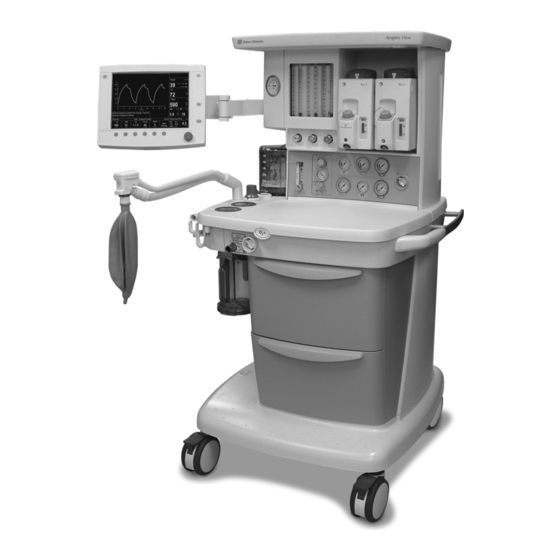
Aespire View Intended use The Aespire anesthesia system is a compact, integrated, and intuitive anesthesia delivery system. The 7900 Ventilator provides mechanical ventilation for patients during surgery as well as monitoring and displaying various patient parameters. The 7900 Ventilator uses a microprocessor-controlled ventilator with internal monitors, electronic PEEP, Volume Mode, and other optional features. -
Page 11: Symbols Used In The Manual Or On The Equipment
1 Introduction Symbols used in the manual or on the equipment Symbols replace words on the equipment, on the display, or in manuals. Warnings and Cautions tell about the dangerous conditions that can occur if the instructions in the manual are not followed. Warnings tell about a condition that can cause injury to the operator or the patient. - Page 12 Aespire View Equipotential Lamp, lighting, illumination Protective earth ground Earth ground Variability Variability in steps Suction bottle outlet Vacuum inlet Vacuum Plus, positive polarity Minus, negative polarity Bag position/manual ventilation Mechanical ventilation Inspiratory flow Expiratory flow Movement in one direction...
- Page 13 Indicates that the waste of electrical and GOST R Russian certification electronic equipment must not be disposed as unsorted municipal waste and must be collected separately. Please contact an authorized representative of Datex-Ohmeda for information concerning the decommissioning of equipment. This way up USB port...
-
Page 14: Typeface Conventions Used
Aespire View Typeface conventions used Menu items are written in bold italic typeface; for example, Main Menu. Messages that are displayed on the screen are enclosed in single quotes: for example, ‘Total pressure exceeds Pmax.’ When referring to different sections and other documents, the names are written in italic typeface and enclosed in double quotes;... - Page 15 1 Introduction Patient airway pressure Pressure controlled ventilation PCV-VG Pressure controlled ventilation - volume guaranteed PEEP Positive end expiratory pressure Pmax Maximum pressure Pmean Average pressure calculated over the patient breath Pinsp Target airway pressure Ppause Positive airway pressure measured at the end of Tpause Ppeak Maximum airway pressure measured during patient...
- Page 16 Aespire View M1132382...
- Page 17 2 System Controls and Menus WARNING Explosion Hazard. Do not use this system with flammable anesthetic agents. Do not use antistatic or electrically-conductive breathing tubes or masks. They can cause burns if used near high frequency surgical equipment. In this section Anesthesia system controls .
-
Page 18: Anesthesia System Controls
Aespire View Anesthesia system controls 1. Light switch 8. Brake 2. Dovetail rails 9. O2 flush button 3. Vaporizer 10. Auxiliary O2 flow control (optional) 4. Pipeline pressure gauge(s) (upper row) 11. Breathing system 5. Cylinder pressure gauge(s) (lower row) 12. - Page 19 2 System Controls and Menus Item, Figure 2-1 Description System switch Set the switch to the On (|) position to permit gas flow and to turn on the system. Integrated suction Turn the switch to MAX for full vacuum. Turn the switch to Off (0) for no vacuum. Turn (optional) the switch to On (|) for adjustable vacuum.
- Page 20 Aespire View 1. Outlet circuit breaker 5. Mains inlet 2. Electrical outlet 6. System circuit breaker 3. Suction items (optional) 7. Cylinder 4. Equipotential stud 8. Pipeline connections Figure 2-2 • Rear view M1132382...
-
Page 21: Advanced Breathing System (Abs) Components
2 System Controls and Menus Advanced breathing system (ABS) components 1. Expiratory check valve 10. Breathing system release 2. Inspiratory check valve 11. Manual bag port 3. Auxiliary common gas outlet (ACGO) switch 12. Adjustable pressure-limiting (APL) valve 4. ACGO 13. - Page 22 Aespire View Item, Figure 2-3 Description Auxiliary common gas outlet Sends fresh gas to the ACGO when the switch is activated. The ACGO (ACGO) switch provides fresh gas to an external manual breathing circuit. Inspiratory flow sensor and Flow sensors provide volume measurements for some monitoring Expiratory flow sensor functions and tidal volume delivery.
-
Page 23: Optional Abs Components
2 System Controls and Menus Optional ABS components 1. Bag support arm 2. EZchange canister system (CO2 bypass) 3. EZchange canister release 4. Condenser drain button 5. Condenser Figure 2-4 • Breathing system options Item, Figure 2-4 Description Bag support arm Squeeze the button to raise or lower the arm. -
Page 24: Vaporizer Controls
Aespire View Vaporizer controls Refer to the vaporizer User’s Reference manual for more detailed information on the vaporizer. 1. Tec 6 series 2. Tec 7 3. Lock lever 4. Concentration control and release 5. Indicators (Tec 6 series) 6. Silence alarm touch key (Tec 6 series) Figure 2-5 •... - Page 25 2 System Controls and Menus Item, Figure 2-5 Description Lock Lever Turn the lever fully clockwise to lock the vaporizer in position. Concentration control and Push the release and turn the concentration control to set the agent release concentration. The Tec 6 series concentration control does not turn as long as the warm-up indicator is on.
-
Page 26: Acgo
Aespire View ACGO Fresh gas flow with anesthetic agent is directed through the Auxiliary Common Gas Outlet (ACGO) on the front of the system when the ACGO switch is in the ACGO position. Mechanical ventilation is not available when operating an auxiliary manual breathing circuit with fresh gas from the ACGO. -
Page 27: Scavenging The Acgo Sample Flow
2 System Controls and Menus Scavenging the A sample of the fresh gas is diverted to the O2 cell in the breathing ACGO sample flow system to show the O2 numerics on the monitor display. This sample flow should be scavenged when an auxiliary manual breathing circuit is used with N2O or volatile anesthetics. -
Page 28: Ventilator Controls
Aespire View Ventilator controls The ventilator controls include touch keys, menu screens, and a control knob (ComWheel). The System switch provides power functions to the ventilator display. The Bag/Vent switch starts and stops mechanical ventilation. 1. High priority alarm indicator 8. -
Page 29: Ventilator Screen
2 System Controls and Menus Ventilator screen O2% low TVexp low Ppeak cmH2O Pmean Ppause TVexp /min l/min Time (sec) Push the knob to confirm the change. Turn the knob to change the setting. Vent On VCV - Volume Control Circle Fresh Gas Flow l/min Pmax... -
Page 30: Using Menus
Aespire View Using menus Main Menu Ppeak cmH2O Ventilation Mode Pmean Alarm Setup Ppause Setup/Calibration SIMV/PSV Screen and Audio Setup PSVPro Cardiac Bypass SIMV-PC TVexp Normal Screen /min l/min Time (sec) Vent On VCV - Volume Control Circle Pmax PEEP... - Page 31 3 Operation WARNING Maintain sufficient fresh gas flow when using sevoflurane. In this section Turning on the system ......3-2 Start mechanical ventilation .
-
Page 32: Turning On The System
Aespire View Turning on the system 1. Plug the power cord into an electrical outlet. Make sure the system circuit breaker is on. • The mains indicator comes on when AC power is connected. • The battery is charging if not already fully charged. -
Page 33: Ventilator Setup
3 Operation Ventilator setup The system has the following mechanical ventilation modes: • Volume Control Ventilation (VCV). The ventilator delivers the tidal volume to the patient at the set respiratory rate (RR). • Pressure Control Ventilation (PCV) (optional). The airway pressure is controlled to the value of Pinsp in every breath. -
Page 34: Changing Ventilator Modes And Settings
Aespire View Changing ventilator 1. Push the Menu key. modes and settings 2. Select Ventilation Mode from the Main Menu. Main Menu Ventilation Mode Alarm Setup Setup/Calibration SIMV/PSV Screen and Audio Setup PSVPro Cardiac Bypass SIMV-PC PCV-VG Normal Screen 3. Use the ComWheel to highlight the desired setting (PSVPro shown), and push the ComWheel to confirm the change. -
Page 35: Alarm Setup
3 Operation Alarm Setup Setting volume Use the volume alarms key to turn the volume alarms on and off. alarms When the alarms are off, an X covers the alarm limits. Use this control during manual ventilation when constant attention is on the patient. Use the End case key to minimize alarms between cases. -
Page 36: Setup/Calibration
Aespire View Setup/Calibration To change or enter Setup and Calibration information: 1. Push the Menu key. 2. Select Setup/Calibration from the Main Menu. Setup/Calibration More Vent Settings O2 Sensor Calibration About Ventilator... Go to Main Menu 3. Use the ComWheel to scroll to the desired submenu. Push the ComWheel to confirm the selection. -
Page 37: Screen And Audio Setup
3 Operation Screen and audio setup To change the audio and visual appearance of the screen: 1. Push the Menu key. 2. Select Screen and Audio Setup from the Main Menu. Screen and Audio Setup Brightness Alarm Volume Alarm Limits Show Units of Measure Show... -
Page 38: Cardiac Bypass
Aespire View Cardiac Bypass Cardiac Bypass suspends alarms for patients on cardiac bypass when the ventilator is not mechanically ventilating. Mechanical ventilation must be off. When mechanical ventilation is turned on, Cardiac Bypass is automatically turned off, the alarms are enabled, and monitoring is available. -
Page 39: Measure Circuit Compliance
3 Operation Measure circuit compliance Exhaled tidal volume (TVexp) measures the gas needed to fill the patient circuit at the measured pressure. The compliance factor can be used to calculate the approximate gas which goes into expanding the compliant patient tubing and not delivered into the patient. 1. -
Page 40: Ezchange Canister (Optional)
Aespire View EZchange canister (optional) Push the absorber canister release to activate the EZchange canister mode. The canister will swing down to the EZchange position. The EZchange canister mode seals the breathing circuit when the canister holder is down. This permits continued ventilation and rebreathing of exhaled gases while replacing the absorber canister. -
Page 41: Condenser (Optional)
3 Operation Condenser (optional) Visually check the condenser reservoir daily. Drain the reservoir daily. 1. Place a container under the reservoir. 2. Push the drain button to empty any water in the condenser. 1. Drain button 2. Reservoir 3. Condenser Figure 3-1 •... -
Page 42: Passive Agss (Optional)
Aespire View Passive AGSS (optional) WARNING Always verify the proper operation of any gas scavenging system; ensure the scavenging system is not occluded. The passive AGSS (Anesthesia Gas Scavenging System) contains both positive and negative pressure relief valves to protect the breathing system and the patient. -
Page 43: Active Agss (Optional)
3 Operation Active AGSS (optional) WARNING Always verify the proper operation of any gas scavenging system; ensure the scavenging system is not occluded. There are several versions of the optional active AGSS (Anesthesia Gas Scavenging System) available depending on the hospital’s type of waste gas disposal system. -
Page 44: Connecting Active Agss With A Flow Indicator
Aespire View • The active low flow system with a 25 mm barb connector is for use with low vacuum disposal systems. It requires an external venturi/ejector system with a 40 to 50 l/min extract flow. A flow indicator on the system indicates when the unit is in operation. -
Page 45: Connecting Active Adjustable Agss
3 Operation Connecting active The active adjustable AGSS option flow rate is limited to 30 l/min with adjustable AGSS this option. To use the optional active AGSS installed on the system which uses the three-liter bag as a visual indicator, connect it as follows: 1. - Page 46 Aespire View 3-16 M1132382...
-
Page 47: Preoperative Checkout
• Test all other system components. If a test fails, do not use the equipment. Have a Datex-Ohmeda trained service representative repair the equipment. In this section Every day before your first patient ....4-2 Before every patient . -
Page 48: Every Day Before Your First Patient
Aespire View Every day before your first patient Check that necessary emergency equipment is available and in good condition. Check that the equipment is not damaged and that components are correctly attached. Check that pipeline gas supplies are connected and cylinders are installed and adequately filled. -
Page 49: Before Every Patient
4 Preoperative Checkout Before every patient Note This check does not need to be done before the first case of the day if the “Every day before your first patient” check was done. Check that necessary emergency equipment is available and in good condition. - Page 50 Aespire View M1132382...
-
Page 51: Preoperative Tests
5 Preoperative Tests In this section Inspect the system ....... . 5-2 Power failure alarm test . -
Page 52: Inspect The System
Aespire View Inspect the system WARNING Do not exceed the top shelf weight limit of 34 kg (75 lb). Make sure that the breathing circuit is correctly connected and not damaged. Replace the breathing circuit if it is damaged. Do not leave gas cylinder valves open if the pipeline supply is in use. -
Page 53: Power Failure Alarm Test
5 Preoperative Tests Power failure alarm test 1. With the System switch set to On, unplug the power cord. 2. Make sure that the power failure alarm sounds. 3. Connect the power cord to the electrical outlet. 4. Verify that the alarm tone stops. Pipeline test 1. -
Page 54: Cylinder Test
Aespire View Cylinder test CAUTION To prevent damage to the system, open the cylinder valves slowly and do not force the flow controls. WARNING Do not leave gas cylinder valves open if the pipeline supply is in use. Cylinder supplies could be depleted, leaving an insufficient reserve supply in case of pipeline failure. -
Page 55: Flow Control Test
5 Preoperative Tests Flow control test WARNING The Link-25 system cannot replace an O2 monitor. Sufficient O2 in the fresh gas may not prevent hypoxic mixtures in the breathing circuit. Nitrous oxide (N2O), if available, flows through the system during this test. Use a safe and approved procedure to collect and remove the N2O. - Page 56 Aespire View 6. Test the Link-25 system by increasing the N2O flow. • Slowly turn the N2O flow control counterclockwise. • Increase the N2O flow as specified in the following table and make sure the O2 flow is as specified.
-
Page 57: Vaporizer Installation
5 Preoperative Tests Vaporizer installation WARNING Use only Datex-Ohmeda, Inc. Selectatec series vaporizers Tec 4 or greater. Do not use a vaporizer if it lifts off the manifold when the lock lever is in the locked position. Do not use the system if more than one vaporizer can be turned on at the same time. -
Page 58: Vaporizer Back Pressure Test
Aespire View Vaporizer back pressure test WARNING Anesthetic agent comes out of the common gas outlet during this test. Use a safe, approved procedure to remove and collect the agent. CAUTION To prevent damage to the vaporizer, turn the flow controls fully clockwise (minimum flow or off) before turning on the system. -
Page 59: Low-Pressure Leak Test
5 Preoperative Tests Low-pressure leak test WARNING Do not use a system that has a low-pressure leak. Anesthetic agent will go into the atmosphere instead of into the breathing circuit. Perform either the “Negative low-pressure leak test” or the “Positive low-pressure leak test”... -
Page 60: Positive Low-Pressure Leak Test
Aespire View WARNING Agent mixtures from the low-pressure leak test stay in the system. Clear the system by flowing O2 at 1 l/min for one minute. 8. Clear the system of agent. • Set the System switch to On. •... -
Page 61: Alarm Tests
5 Preoperative Tests WARNING Agent mixtures from the low-pressure leak test stay in the system. Clear the system by flowing O2 at 1 l/min for one minute. 12. Clear the system of agent. • Set the O2 flow to 1 l/min. •... - Page 62 Aespire View 12. Test the O2 monitor and alarms (alarms other than Low O2 and High O2 may occur). • Remove the O2 cell, and make sure that the cell measures approximately 21% O2 in room air. • Push the Menu key.
-
Page 63: Breathing System Tests
5 Preoperative Tests Breathing system tests 1. Make sure that the auxiliary equipment is functioning correctly. 2. Verify that AGSS is functioning correctly. • Some breathing systems with active AGSS have a flow indicator on the side. Make sure that the flow indicator shows a flow in the green range. -
Page 64: Breathing Circuit Test
Aespire View Breathing circuit test 1. Set the System switch to On. 2. Set the Bag/Vent switch to Bag. 3. Occlude the bag port. 4. Set the APL valve to 70 cmH2O. 5. Set the O2 flow to 250 ml/min. -
Page 65: Monitor And Ventilator Tests
5 Preoperative Tests Monitor and ventilator tests 1. Connect a test lung to the patient connection. 2. Set the Bag/Vent switch to Bag. 3. Set the System switch to On. 4. Push the Menu key. 5. Select Ventilation Mode - VCV. 6. - Page 66 Aespire View 12. Set the ventilator controls and alarm limits to clinically appropriate levels. 13. Prepare the system. • Turn all vaporizers off. • Set the APL valve to MIN. • Set the Bag/Vent switch to Bag. • Set all flow controls to minimum.
-
Page 67: Alarms And Troubleshooting
If an alarm occurs, safeguard the patient first before performing troubleshooting or doing repair procedures. Do not use malfunctioning equipment. Contact a Datex-Ohmeda trained representative for service. No repair should ever be attempted by anyone not having experience in the repair of devices of this nature. See the “Repair policy”... -
Page 68: Alarms
Aespire View Alarms When an alarm occurs during a case, an alarm tone sounds and the alarm message is displayed in the alarm message field. The alarm message area has room for four alarms to be shown at one time. If more than four alarms occur, the alarms cycle every two seconds. -
Page 69: Latching Alarms
6 Alarms and Troubleshooting Latching alarms Some patient parameter alarms continue to be displayed (latch) when the alarm condition is corrected. When an alarm is latched, the alarm messages show in white text on a black background. Latching alarm Flashing parameter O2% low No O2 pressure None... -
Page 70: List Of Alarms
Battery charger fail Informational The current in the battery charging System is operational, but may fail on battery if circuit is too high. mains power is lost. Contact a Datex-Ohmeda trained service representative. Battery charging Informational Battery is not fully charged. - Page 71 Informational Battery voltage greater than 16 V for System is operational, but may fail on battery if 10 seconds. mains power is lost. Contact a Datex-Ohmeda trained service representative. Battery failure low Informational The battery voltage is too low (less...
- Page 72 Contact a Datex-Ohmeda trained service representative. Memory (flash) Minimum shutdown Ventilator malfunction. Ventilate manually. Monitoring is not reliable. failure (High) Contact a Datex-Ohmeda trained service representative. Memory (redundant Minimum shutdown Ventilator malfunction. Ventilate manually. Monitoring is still available. storage) fail (High) Contact a Datex-Ohmeda trained service representative.
- Page 73 Positive SIB Vref Minimum shutdown Ventilator malfunction. Ventilate manually. Monitoring is still available. out-of-range (High) Contact a Datex-Ohmeda trained service representative. Ppeak high High Ppeak is greater than Pmax. The Verify Pmax and other controls are set correctly. ventilator cycles to expiration.
- Page 74 Continue to use volume control ventilation or PEEP or PSV. control unavailable. ventilate manually. Shut down system as soon as possible. Contact a Datex-Ohmeda trained service representative. The sustained pressure threshold is calculated from the pressure limit setting. The sustained limit is calculated as follows: For Pmax less than or equal to 30 cmH2O, the sustained pressure limit is 6 cmH2O.
-
Page 75: Minimum System Shutdown And Monitoring Alarms
This condition prevents mechanical ventilation and monitoring. If this condition occurs: • Ventilate manually. • Use a stand-alone monitor. • Cycle system power (On-Standby-On). If the alarm clears, restart mechanical ventilation. If the alarm does not clear, contact a Datex-Ohmeda trained service representative. M1132382... -
Page 76: Alarm Ranges
Aespire View Alarm ranges Alarm Range Increment Default O2% high Off, 21-99% O2% low 18-99% MVexp high Off, 0.5-30 l/min 0.5 l/min 10.0 l/min MVexp low Off, 0.1-10 l/min 0.1 l/min 2.0 l/min TVexp high 20-1600 ml 20 ml 1000 ml... - Page 77 6 Alarms and Troubleshooting 6. Test the O2 alarms. • Remove the O2 cell from the breathing circuit and make sure it measures approximately 21% O2 in room air. • Set the O2 low alarm limit to 50%. Make sure the O2% low alarm occurs.
-
Page 78: Breathing System Problems
Aespire View Breathing system problems System Problem Solution Gas scavenging flow is Scavenging extract flow Use a different scavenging too low or too high. problem. extraction system. Verify flow is within specification. Filter blockage. Active systems Replace the filter. See have a flow indicator. -
Page 79: Electrical Problems
6 Alarms and Troubleshooting Electrical problems WARNING If a circuit breaker opens frequently, do not use the system. Have a Datex-Ohmeda trained service representative repair the system. System Problem Solution Mains indicator is not on. The electrical power cable is not Connect the power cable. -
Page 80: Pneumatic Problems
Aespire View Pneumatic problems System Problem Solution High-pressure leak test Controls are not set correctly. Make sure that no gas is fails. flowing, turn off the auxiliary flowmeter, and repeat the test. Incorrect cylinder connection. Make sure that there is only... -
Page 81: User Maintenance
7 User Maintenance WARNING To help prevent fires: • Only use lubricants approved for anesthesia or O2 equipment, such as Krytox. • Do not use lubricants that contain oil or grease. They may burn or explode in high O2 concentrations. •... -
Page 82: Repair Policy
Replace damaged parts with components manufactured or sold by Datex-Ohmeda. Then test the unit to ascertain that it complies with Datex-Ohmeda’s published specifications. Contact a Datex-Ohmeda Field-Service Representative for service assistance. -
Page 83: User Maintenance
Replace the receiver filter (if equipped - active gas scavenging only). Datex-Ohmeda This is the minimum level of maintenance recommended by approved service Datex-Ohmeda. Local regulations may contain additional maintenance requirements. Datex-Ohmeda advocates compliance with local regulations which meet or exceed this minimum level of maintenance. Minimum Frequency... -
Page 84: O2 Cell Replacement
Aespire View O2 cell replacement WARNING Handle and dispose of O2 cells according to site biohazard policies. Do not incinerate. 1. Pull the latch to unlock the flow sensor module. 2. Pull the flow sensor module out of the breathing system. -
Page 85: O2 Cell Calibration
7 User Maintenance O2 cell calibration WARNING Do not perform O2 cell calibration while the system is connected to a patient. The O2 cell must be calibrated at the same environment pressure at which it will be used to monitor oxygen delivery in the patient circuit. -
Page 86: 100% O2 Cell Calibration
Aespire View 100% O2 cell Complete a 21% O2 cell calibration before performing a 100% O2 cell calibration calibration. 1. Make sure that the O2 cell is in the circuit. 2. After performing a 21% calibration, select 100% O2. 3. Push the O2 flush button for 5 seconds and set the O2 flow to 5 l/min and set other gases to minimal flow. -
Page 87: Prevent Water Buildup
7 User Maintenance Prevent water buildup Water is created from exhaled gas and a chemical reaction between CO2 and the absorbent. Water buildup increases when the system is used at low fresh gas flows. At low flows, more CO2 stays in the absorber producing water and more moist exhaled gas remains in the absorber. - Page 88 Aespire View M1132382...
-
Page 89: Setup And Connections
8 Setup and Connections In this section Canister setup........8-4 Electrical connections . - Page 90 Aespire View WARNING Datex-Ohmeda strongly recommends the use of O2 monitoring with this equipment. Refer to local standards for mandatory monitoring. European, international, and national standards require the following monitoring be used with this system: • Exhaled volume monitoring. •...
- Page 91 8 Setup and Connections To protect the patient when electrosurgical equipment is used: • Monitor the correct operation of all life support and monitoring equipment. • Keep backup manual ventilation available in case the electrosurgical equipment prevents safe use of the ventilator.
-
Page 92: Canister Setup
Aespire View Canister setup 1. Canister support pin 2. Canister handle 3. Disposable Multi Absorber canister 4. Absorbent 5. Expiratory water reservoir 6. Canister release latch 7. Reusable Multi Absorber canister Figure 8-1 • Canister M1132382... - Page 93 Reusable Multi Absorber. Both versions are removed and installed on the breathing system in the same way. Each canister holds 800 grams of loose absorbent. Datex-Ohmeda recommends Medisorb absorbent. Both absorber versions should only be used with mixtures of air, oxygen, nitrous oxide, halothane, enflurane, isoflurane, desflurane and sevoflurane.
-
Page 94: When To Change The Absorbent
Aespire View When to change the A gradual color change of the absorbent in the canister indicates absorbent absorption of carbon dioxide. The color change of the absorbent is only a rough indicator. Use carbon dioxide monitoring to determine when to change the canister. -
Page 95: Removing An Ezchange Canister
8 Setup and Connections Removing an 1. Hold the canister by the handle and push the canister cradle EZchange canister release latch to unlock the canister cradle. 2. Slide the canister up and out of the cradle. Reusable Multi 1. Turn the canister upside down and, using your thumbs, turn the Absorber canister cover locking ring counterclockwise to unlock it. - Page 96 Aespire View 3. Lift off the cover to remove it. 4. Remove and properly discard the foam filters, the absorbent, and any water in the reservoir. WARNING Be careful when draining condensate from the absorber. The liquid is caustic and may burn skin.
-
Page 97: Electrical Connections
8 Setup and Connections WARNING The filters must be in place to help prevent dust and particles from entering the breathing circuit. 7. When replacing the canister, make sure that it is seated properly on the support pins or in the EZchange canister module before latching it into place. -
Page 98: Mains Inlet
Aespire View Mains inlet Arrow shows the mains power inlet and cord. Serial port The system has an RS-232C electrical interface. The RS-232C connector allows serial input/output of commands and data. The 15- pin connector is located on the back of the display unit. -
Page 99: Scavenging
8 Setup and Connections Scavenging The scavenging assembly is located below the bellows on the breathing system. Adapters may be necessary to interface to the scavenging connector. See the “Operation” section for more scavenging information. Sample gas return Connect the sample gas exhaust tube from the airway module to the port gas return port. -
Page 100: Suction Regulator (Optional)
Aespire View Suction regulator Venturi regulators use the system air or O2 supply. Vacuum (optional) regulators must be connected to an external vacuum supply. 1. External vacuum (non-venturi) connection 2. Venturi muffler 3. Collection bottle connection 4. Splash guard 5. Overflow safety trap... -
Page 101: How To Install Gas Cylinders
8 Setup and Connections How to install gas cylinders CAUTION Do not leave gas cylinder valves open if the pipeline supply is in use. Cylinder supplies could be depleted, leaving an insufficient reserve supply in case of pipeline failure. Pin indexed cylinder 1. -
Page 102: High-Pressure Leak Test
Aespire View High-pressure leak test Note Datex-Ohmeda recommends testing one cylinder at a time. 1. Turn on the system. 2. Disconnect pipeline supplies. 3. Turn off the auxiliary O2 flowmeter and the venturi suction (if equipped). 4. Open the cylinder. -
Page 103: Parts
9 Parts This section lists user-replaceable parts only. For other components, refer to the Technical Reference manual. In this section Flow sensor module ....... 9-2 Exhalation valve assembly . -
Page 104: Flow Sensor Module
Aespire View Flow sensor module Item Description Stock number Flow sensor module (does not include flow sensors) 1407-7001-000 Flow sensor cover 1407-3000-000 Flow sensor cuff 1407-3004-000 Flow sensor, disposable (plastic) non-offset 1503-3858-000 Flow sensor, disposable (plastic) offset 1503-3856-000 Flow sensor, autoclavable (metal) -
Page 105: Breathing Circuit Module
9 Parts Breathing circuit module Item Description Stock number Breathing circuit module (does not include O2 cell, 1407-7002-000 o-ring, or cable) Check valves circuit lens 1407-3101-000 Check valve assembly 1406-8219-000 O-ring for O2 cell or plug 1406-3466-000 O2 cell (includes o-ring) 6050-0004-110 Cable, O2 cell 1009-5570-000... -
Page 106: Bellows Assembly
Aespire View Bellows assembly Item Description Stock number Bellows housing 1500-3117-000 Bellows 1500-3378-000 1500-3351-000 Pressure relief valve assembly 1500-3377-000 Latch, rim 1500-3352-000 Manifold, bellows base 1407-3702-000 Bellows base with latch 1407-7006-000 Seal, base 1500-3359-000 Diaphragm, APL 1406-3331-000 Cage, APL 1406-3333-000... -
Page 107: Absorber Canister
9 Parts Absorber canister Item Description Stock number Multi absorber, reusable (includes 40 pack of foam) 1407-7004-000 (does not include absorbent) Cover assembly, CO2 canister 1009-8240-000 Foam, CO2 canister (pack of 40) 1407-3201-000 O-ring 1407-3204-000 Canister, CO2 with handle 1407-3200-000 Multi absorber, disposable, white to violet, (pack of 6) 8003138 Multi absorber, disposable, pink to white (pack of 6) 8003963... -
Page 108: Agss
Aespire View AGSS Description Stock number Common Cap 3.18 barb silicone 1406-3524-000 Connector, inlet 30 mm male to 9 mm male M1003134 Connector, inlet 30 mm male to 30 mm male M1003947 O-ring for connector, 21.95 ID 1406-3558-000 O-ring for receiver, 22 ID 1407-3104-000 O-ring for thumbscrews, 4.47 ID... -
Page 109: Ezchange Canister System
9 Parts EZchange canister system Item Description Stock number EZchange canister module, includes valve and cap 1407-7021-000 Valve 1407-3126-000 1407-3130-000 Condenser 1407-7024-000 EZchange canister module with condenser 1407-7027-000 M1132382... -
Page 110: Condenser
Aespire View Condenser Item Description Stock number Condenser assembly (includes module and 1407-7026-000 condenser) Condenser module 1407-7025-000 Condenser 1407-7024-000 M1132382... -
Page 111: Test Tools And System Parts
9 Parts Test tools and system parts Description Stock number Cylinder gasket (pin indexed cylinders only) 0210-5022-300 Cylinder wrench (DIN 477 and high-pressure hose) 1202-3651-000 Cylinder wrench for pin-indexed cylinder 0219-3415-800 DIN O2 plug (cylinder connection) 1202-7146-000 Handle for yoke tee 0219-3372-600 Negative low pressure leak test device 0309-1319-800... - Page 112 Aespire View 9-10 M1132382...
-
Page 113: Specifications And Theory Of Operation
10 Specifications and Theory of Operation Important All specifications are nominal and subject to change without notice. Note All displayed values are shown at ambient temperature and pressure dry. In this section System pneumatic circuits ......10-2 Pneumatic specifications . -
Page 114: System Pneumatic Circuits
Aespire View System pneumatic circuits Figure 10-1 • Pneumatic circuit diagram 10-2 M1132382... - Page 115 10 Specifications and Theory of Operation 1. Auxiliary O2, 0-10 l/min (optional) 36. Scavenging pressure relief valve, 1.0 kPa (10 cmH2O) 2. O2 flush 3. 241 kPa (35 psi) second O2 regulator 37. Gas to scavenging: 0-10 l/min drive gas, 0-10 l/min patient and fresh gas, 0-20 l/min total typical flow 4.
-
Page 116: Gas Supplies
Aespire View Gas supplies Pressurized gas supplies enter the system through a pipeline or cylinder connection. All connections have indexed fittings, filters, and check valves. Gauges show the cylinder and pipeline pressures. A regulator decreases the cylinder pressures to the appropriate system pressure. -
Page 117: Mixed Gas
10 Specifications and Theory of Operation Mixed gas The mixed gas goes from the flowmeter outlet through the vaporizer that is ON, to the fresh gas outlet, and into the breathing system. A pressure relief valve sets the maximum outlet pressure. EZchange canister When activated, this module permits continued ventilation and rebreathing of exhaled gases without any gas passing through the... -
Page 118: Electrical Block Diagram
Aespire View Electrical block diagram Figure 10-2 • Electrical block diagram 10-6 M1132382... -
Page 119: Electrical Power
10 Specifications and Theory of Operation 1. Anesthesia system 23. Breathing system 2. Power cord 24. Bag/Ventilator switch 3. AC inlet with breaker and line filter 25. ABS on switch 4. Isolation transformer 26. Canister switch 5. Inrush board 27. CO2 bypass switch 6. -
Page 120: Power Cord
• The system functions to specifications through the transition to battery power. CAUTION Contact a Datex-Ohmeda trained service representative to replace or disconnect the battery if the equipment is not likely to be used for an extended time. Important Batteries must be disposed of in accordance with applicable regulatory requirements in effect at the time and place of disposal. -
Page 121: Flow Specifications
10 Specifications and Theory of Operation Flow specifications Pneumatic flow Parameter Range Flush flow 35 to 75 l/min Flow range Minimum O2 flow 50 ml/min • 0.05 to 0.95 l/min • 1 to 15 l/min • 0.05 to 0.95 l/min •... -
Page 122: Breathing System Specifications
Aespire View Breathing system specifications Volume Ventilator side 2730 ml; bag side 1215 ml With EZchange canister system and condenser: • Ventilator side 3445 ml • Bag side 1930 ml Absorbent 950 ml canister Connections Auxiliary Common Gas Outlet: ISO 5356 type connector on the front of the system (standard 22 mm OD or 15 mm ID conical friction fit connectors). -
Page 123: Gas Scavenging
10 Specifications and Theory of Operation Pressure flow data (APL valve completely open) Flow (l/min) Flow (l/s) APL pressure cmH2O 0.05 0.78 0.17 1.14 0.51 1.43 2.61 1.17 3.21 Gas scavenging All scavenging Positive pressure relief 10 cmH2O Passive scavenging Negative pressure relief 0.3 cmH2O Outlet connector... -
Page 124: Physical Specifications
Aespire View Physical specifications All specifications are approximate values and can change without notice. CAUTION Do not subject the system to excessive shock and vibration. Do not place excessive weight on flat surfaces or drawers. System Height 136 cm (53.5 in) Width 75 cm (29.5 in) -
Page 125: Suction Regulators (Optional)
10 Specifications and Theory of Operation Suction regulators (optional) Venturi Suction Regulator Performance Category Pharyngeal Suction Supply Air or O2 from system gas supply Drive Gas Consumption* 28 l/min with pipeline drive gas at 280 kPa (41 psi) 52 l/min with pipeline drive gas at 600 kPa (87 psi) Maximum Vacuum** 600 mmHg with pipeline drive gas at 280 kPa (41 psi) 550 mmHg with pipeline drive gas at 600 kPa (87 psi) -
Page 126: Ventilator Theory
Aespire View Ventilator theory The ventilator pneumatics are located in the rear of the breathing system. A precision flow valve controls gas flow to the patient. During inspiration, this gas flow closes the exhalation valve and pushes the bellows down. During expiration, a small flow pressurizes the exhalation diaphragm to supply PEEP pressure. -
Page 127: O2 Monitoring Theory Of Operation
10 Specifications and Theory of Operation O2 monitoring theory O2 monitoring measures O2 concentration in the patient circuit. The of operation O2 concentration measured from the O2 cell is shown on the ventilator display. The O2 sensor is an electrochemical device (galvanic cell). Oxygen diffuses through a membrane into the cell and oxidizes a base metal electrode. - Page 128 Aespire View 1. Paw 2. Pmax 3. PEEP 4. Time Figure 10-3 • Volume control diagram Volume control supplies a set tidal volume. The ventilator calculates a flow based on the set tidal volume and the length of the inspiratory time from the I:E and respiratory rate settings.
- Page 129 10 Specifications and Theory of Operation 1. Paw 2. Pmax 3. Pinsp 4. PEEP 5. Time Figure 10-4 • Pressure control diagram Pressure control supplies a constant set pressure during inspiration. The ventilator calculates the inspiratory time from the respiratory rate and I:E ratio settings.
- Page 130 Aespire View SIMV/PSV 1. Mandatory SIMV breath 2. Spontaneous pressure supported breath 3. Paw 4. Psupport 5. PEEP Figure 10-5 • SIMV/PSV diagram Synchronized Intermittent Mandatory Ventilation with Pressure Support (SIMV/PSV) is a mode in which periodic volume breaths are delivered to the patient at preset intervals (time-triggered).
- Page 131 10 Specifications and Theory of Operation PSVPro 1. Paw 2. PEEP 3. Time Figure 10-6 • PSVPro diagram PSVPro is pressure supported ventilation with apnea backup. PSVPro is a spontaneous mode of ventilation that provides a constant pressure once the ventilator senses that the patient has made an inspiratory effort.
- Page 132 Aespire View When the ventilator switches to the backup mode, the alarm text “Backup Mode active’ displays and remains in the low priority message site until PSVPro is reinstated or until another mode is selected. To reactivate the PSVPro mode the user must go into the Ventilation Mode menu and select PSVPro.
- Page 133 10 Specifications and Theory of Operation SIMV-PC 1. Mandatory pressure control breath 2. Spontaneous pressure supported breath 3. Paw 4. Psupport 5. PEEP 6. Time Figure 10-7 • SIMV-PC diagram Synchronized Intermittent Mandatory Ventilation with Pressure Controlled Ventilation is a mode in which a relatively slow mandatory breathing rate is set with pressure-controlled breathing.
- Page 134 Aespire View PCV-VG 1. Paw waveform 2. Tinsp 3. Texp 4. Variable pressure to deliver desired TV 5. PEEP 6. Flow waveform 7. TV Figure 10-8 • PCV-VG waveforms In PCV-VG, a tidal volume is set and the ventilator delivers that volume using a decelerating flow and a constant pressure.
-
Page 135: Ventilator Operating Specifications
10 Specifications and Theory of Operation Ventilator operating specifications Pneumatics Gas source Anesthesia system Gas composition Medical air or O2 Nominal supply pressure 350 kPa (51 psi) Pressure range at inlet 240 to 700 kPa (35 to 102 psi) Flow valve range 1 to 120 l/min at 240 kPa (35 psi) Fresh gas compensation... -
Page 136: Ventilator Accuracy Data
Aespire View Expected cell life Four months of shelf life (23°C room air) and one year of normal operation. Ventilator accuracy data The following accuracy data are based on patient conditions and settings described in ASTM F1101. The ventilator is assumed to be operating in volume mode. - Page 137 10 Specifications and Theory of Operation Figure 10-9 • Gas composition related errors 10-25 M1132382...
-
Page 138: Electromagnetic Compatibility (Emc)
Aespire View Electromagnetic compatibility (EMC) WARNING Changes or modifications to this equipment not expressly approved by the manufacturer could cause EMC issues with this or other equipment. Contact the manufacturer for assistance. This device is designed and tested to comply with applicable regulations regarding EMC as follows. -
Page 139: Guidance And Manufacturer's Declaration
10 Specifications and Theory of Operation Guidance and The system is suitable for use in the specified electromagnetic manufacturer’s environment. The customer and/or the user of the system should assure that it is used in an electromagnetic environment as described declaration - below. - Page 140 Aespire View Radiated immunity Electromagnetic environment guidance Immunity test IEC 60601-1-2 test Level Compliance level Recommended separation distance Portable and mobile RF communications equipment should be used no closer to any part of the system, including cables, than the recommended separation...
-
Page 141: Recommended Separation Distances
10 Specifications and Theory of Operation Recommended The system is intended for use in the electromagnetic environment in separation distances which radiated RF disturbances are controlled. The customer or the user of the system can help prevent electromagnetic interference by maintaining a minimum distance between portable and mobile RF communications equipment (transmitters) and the system as recommended below, according tho the maximum power of the... -
Page 142: Electrical Safety
Aespire View Electrical safety WARNING The system provides connections for items such as printers, visual displays and hospital information networks (only connect items that are intended to be part of the system). When these items (non-medical equipment) are combined with the system, these precautions must be followed: •... -
Page 143: Iec 60601-1 Classification
10 Specifications and Theory of Operation IEC 60601-1 Classification This system is classified as follows: • Class I Equipment. • Type B Equipment. • Ordinary Equipment. • Not for use with flammable anesthetics. • Continuous operation. Standards Devices used with this anesthesia system shall comply with the following standards where applicable: •... -
Page 144: System Components
Aespire View System components Integral This anesthesia system contains the following integral components, monitoring devices, alarm systems, and protection devices that comply with European, international, and national standards: • Breathing system pressure-measuring device. • Airway pressure-limitation device. • Exhaled-volume monitor. - Page 145 Index Controls anesthesia system Absorber canister vaporizer filling ventilator 2-12 parts Cylinder removing installation 8-13 setup ACGO 2-10 positive low-pressure leak test 5-10 scavenging the ACGO sample flow Electrical safety 2-11 10-30 Advanced breathing system Electromagnetic compatibility 10-26 optional components EZchange canister AGSS removal...
- Page 146 Aespire View O2 cell Scavenging 8-11 calibration a gas monitor sample flow 2-11 replacement ACGO sample flow 2-11 O2 flush button from an auxiliary manual breathing circuit 2-11 specifications 10-11 Serial port 8-10 Parts Specifications absorber canister breathing system 10-10...
- Page 147 Ventilator accuracy data 10-24 modes 10-15 operating specifications 10-23 setup theory 10-14 Ventilator screen 2-13 Water buildup prevent Zeroing flow sensor M1132382...
- Page 148 Aespire View M1132382...
- Page 149 For a period of twelve (12) months from the date of original delivery to Buyer or to Buyer’s order, but in no event for a period of more than two years from the date of original delivery by Datex-Ohmeda to a Datex-Ohmeda Authorized Dealer, this Product, other than its...
- Page 150 Aespire View User’s Reference Manual English M1132382 02 09 002 18 05 02 Printed in USA ©Datex-Ohmeda, Inc. All rights reserved...
Need help?
Do you have a question about the Aespire View and is the answer not in the manual?
Questions and answers