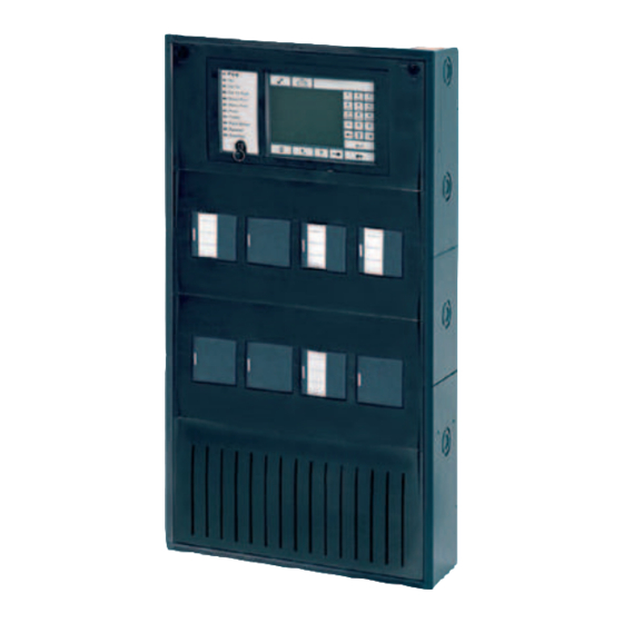
Bosch FPA‑5000 System Information
Modular fire panel
Hide thumbs
Also See for FPA‑5000:
- Wiring manual (326 pages) ,
- System description (178 pages) ,
- System information (174 pages)
Table of Contents
Advertisement
Advertisement
Table of Contents

Subscribe to Our Youtube Channel
Related Manuals for Bosch FPA‑5000


Summary of Contents for Bosch FPA‑5000
- Page 1 Modular fire panel FPA‑5000 | FPA‑1200 System Information...
-
Page 3: Table Of Contents
UPS 2416 A Universal Power Supply 24 V/6 A Panel Rails 4.7.1 PRS-0002-C Panel Rail Short for 2 Modules 4.7.2 PRD 0004 A Panel Rail Long for 4 Modules 4.7.3 Panel Rail Installation Bosch Sicherheitssysteme GmbH System Information 07.2020 | 12.0 | F.01U.028.089... - Page 4 PRD 0004 A Panel Rail Long for 4 Modules 7.3.5 FPO‑5000‑PSB1/FPO‑5000‑PSB‑CH Power Supply Brackets 7.3.6 UPS 2416 A Universal Power Supply 24 V/6 A Panel Controller and Remote Keypad 7.4.1 7.4.2 Remote Keypad 07.2020 | 12.0 | F.01U.028.089 System Information Bosch Sicherheitssysteme GmbH...
- Page 5 8.3.3 Accessories for housing 8.3.4 Panel rails 8.3.5 Power supply units 8.3.6 Panel controller | Remote keypad 8.3.7 Functional modules 8.3.8 Cable sets Special Applications 8.4.1 Controlling Extinguishing Systems Index Bosch Sicherheitssysteme GmbH System Information 07.2020 | 12.0 | F.01U.028.089...
-
Page 6: Notes
Installation must only be carried out by authorized specialist personnel. Notice! Have maintenance and inspection work carried out regularly by trained, qualified personnel. Bosch recommends a functional and visual inspection at least once a year. Notice! The fire panel is designed for indoor installation. - Page 7 The panels can be networked with one another and with the remote keypad using the Ethernet and the CAN bus interfaces. The fire panel can be connected to the Bosch Hierarchy panel (UGM) and thus integrated into large-scale systems. Connection to the Bosch Building Integration System BIS is possible via an Ethernet interface using an OPC server.
- Page 8 O U T 4 IN 4 F B 1 F B 2 Figure 2.1: Example configuration Position Description Position Description Functional modules Power supply unit Panel controller Housing (in this case: HCP 0006 A) 07.2020 | 12.0 | F.01U.028.089 System Information Bosch Sicherheitssysteme GmbH...
- Page 9 After a replacement, only the connectors need to be reinserted; there is no need for extensive rewiring. Module Description Function ANI 0016 A Annunciator module Indicating system statuses, with 16 red and 16 yellow freely programmable LEDs Bosch Sicherheitssysteme GmbH System Information 07.2020 | 12.0 | F.01U.028.089...
- Page 10 Fire service operating panel or a Fire brigade information center to the fire panel. Notice! Safety Systems Designer can be used to plan fire alarm systems that conform to the relevant limits (e.g. in terms of cable length and power supply). 07.2020 | 12.0 | F.01U.028.089 System Information Bosch Sicherheitssysteme GmbH...
-
Page 11: Panel Controller
The FSP-5000-RPS programming software enables adaption to project- and country-specific requirements. For operating the panel controller and the keypad refer to the user manual (F.01U.258.929) available for download at www.boschsecurity.com. Bosch Sicherheitssysteme GmbH System Information 07.2020 | 12.0 | F.01U.028.089... - Page 12 The language for the menu navigation can be selected as required. Below the status LEDs is a key switch with two programmable positions, e.g.: – for switching between day/night mode, or 07.2020 | 12.0 | F.01U.028.089 System Information Bosch Sicherheitssysteme GmbH...
-
Page 13: Fpe-8000-Spc | Fpe-8000-Ppc | Fpe-2000-Spc | Fpe-2000-Ppc Panel Controller
Do not use any pointed or sharp objects (e.g. screw drivers, pens, etc.) when operating the touch-sensitive display. The touchscreen may not be exposed to direct sunlight. Both can seriously damage the touchscreen. Bosch Sicherheitssysteme GmbH System Information 07.2020 | 12.0 | F.01U.028.089... - Page 14 Logical zone and sub-address of the triggering element At any time, the operator can request a status overview for each evacuation zone and each output connected to the fire protection equipment. 07.2020 | 12.0 | F.01U.028.089 System Information Bosch Sicherheitssysteme GmbH...
- Page 15 Additionally, you can connect a log printer via a serial interface module for real-time printing incoming messages. Installation Refer to the Installation guide for FPE-8000-SPC | FPE-8000-PPC | FPE-2000-SPC | FPE-2000- PPC panel controller (F.01U.347.557) available for download at www.boschsecurity.com. Bosch Sicherheitssysteme GmbH System Information 07.2020 | 12.0 | F.01U.028.089...
-
Page 16: Remote Keypad
FPE-8000-FMR Remote keypad The remote keypad can be used to perform the same operating procedures as the control panel, enabling variable operation of a networked system. It has the following functional elements. 07.2020 | 12.0 | F.01U.028.089 System Information Bosch Sicherheitssysteme GmbH... - Page 17 For operating the panel controller and the keypad refer to the user manual (F.01U.378.877) available for download at www.boschsecurity.com. Refer to – MPC Panel Controller, page 89 – MPC, page 148 Bosch Sicherheitssysteme GmbH System Information 07.2020 | 12.0 | F.01U.028.089...
-
Page 18: Housings For Frame Installation
The mounting frames are available in three sizes: – FBH 0000 A Mounting Frame Large – FMH 0000 A Mounting Frame Medium – FSH 0000 A Mounting Frame Small The housings for frame installation require the following mounting frames for surface-mounted version: 07.2020 | 12.0 | F.01U.028.089 System Information Bosch Sicherheitssysteme GmbH... - Page 19 The table below shows the maximum number of: – Panel controllers – UPS power supply units – Batteries Housing type Panel controller UPS power Batteries supply units CPH 0006 A 2 x 45 Ah MPH 0010 A Bosch Sicherheitssysteme GmbH System Information 07.2020 | 12.0 | F.01U.028.089...
- Page 20 - Cable set for battery connection PMF 0004 A - Housing, painted sheet steel - Power supply bracket - Cable set for battery connection USF 0000 A - Housing, painted sheet steel - Mounting plate 07.2020 | 12.0 | F.01U.028.089 System Information Bosch Sicherheitssysteme GmbH...
-
Page 21: Housings For Wall Mounting
Panel rails (short PRS-0002-C, long PRD 0004 A) Housing type Modules Short rail Long rail HCP 0006 A HBC 0010 A HBE 0012 A PSS 0002 A PSB 0004 A DIB 0000 A Bosch Sicherheitssysteme GmbH System Information 07.2020 | 12.0 | F.01U.028.089... -
Page 22: System Overview
FDT 0001 A The technical data for the housings can be found in Housings for Wall Mounting, page 146 . System Overview The following figure shows a typical fire detection system design. 07.2020 | 12.0 | F.01U.028.089 System Information Bosch Sicherheitssysteme GmbH... - Page 23 The devices approved for connection to the CZM 0004 A Conventional Module or the FLM-420/4‑CON Conventional Interface Module can be found in the relevant compatibility lists: Module/interface module Compatibility list CZM 0004 A F.01U.164.327 FLM-420/4‑CON F.01U.079.455 Bosch Sicherheitssysteme GmbH System Information 07.2020 | 12.0 | F.01U.028.089...
- Page 24 ADW 511A • N4387A • • Infrared flame detectors DF1192 • DF1101A-Ex • 016519 • • 016589 • • Duct smoke detectors FAD-420-HS-EN • • 1) Connection via DCA1192/SB3 only 07.2020 | 12.0 | F.01U.028.089 System Information Bosch Sicherheitssysteme GmbH...
- Page 25 ROLP-W-LX/ROLP- • R-LX FNM-420-A/-B/-A- • • FNM-420U-A • • FNM-420V-A • • DS 10 • HPW 11 • Visual notification appliances FNS-320 • FNS-P400RTH • FNS-420-R • • SOL-LX • Bosch Sicherheitssysteme GmbH System Information 07.2020 | 12.0 | F.01U.028.089...
- Page 26 Connection via Transmission AT3000 IP/GSM ENO 0000 B devices AT3000 IP/GSM/Analog AT3000 IP/GSM/ISDN AT5000 IP/GPRS ENO 0000 B Product group Product name Connection via Key deposits FMS-KR-BASIC ENO 0000 B FMS-KR-BASIC-RPF 07.2020 | 12.0 | F.01U.028.089 System Information Bosch Sicherheitssysteme GmbH...
-
Page 27: Networking
The Praesideo, PAVIRO or Plena voice alarm system can be connected via a data transmission line to the panel. This enables the panel to control voice alarm zones. The control can be defined down to the individual detector level. Bosch Sicherheitssysteme GmbH System Information 07.2020 | 12.0 | F.01U.028.089... -
Page 28: Planning
(creeping short circuit and creeping open monitoring). – Conventional detectors of the Bosch portfolio for fire products can be connected using one of the following methods: – Using the CZM 0004 A 4 Zone Conventional Module The module provides four DC primary lines (zones). -
Page 29: Detection Points
ENO 0000 B requires 1 detection point only if a FSE release element is connected and programmed using the FSP-5000-RPS programming software FPP‑5000‑TI Interface Modules Detection Points FLM-420/4CON Up to 2 Bosch Sicherheitssysteme GmbH System Information 07.2020 | 12.0 | F.01U.028.089... -
Page 30: Address Setting
Manual address setting is required for T-tap topologies. No matter what topology you set up: If you decide on manual address setting, then you have to select T-tap in FSP-5000-RPS. 07.2020 | 12.0 | F.01U.028.089 System Information Bosch Sicherheitssysteme GmbH... -
Page 31: Topologies In Local Security Network
Topologies in LSN improved with automatic address setting LSN 0300 A LSN 0300 A LSN 1500 A LSN 1500 A Loop Stub Tab. 3.3: Topologies in LSN improved with automatic address setting Bosch Sicherheitssysteme GmbH System Information 07.2020 | 12.0 | F.01U.028.089... - Page 32 Since in a loop topology each element can be reached on an alternative way for failure handling, prefer the loop topology. Consider that regional authorities may require an upper limit to the number of elements that can be lost due to a single fault. 07.2020 | 12.0 | F.01U.028.089 System Information Bosch Sicherheitssysteme GmbH...
-
Page 33: Failure Handling In Local Security Network
The feature is available with LSN bus module firmware 1.0.55 and higher. In regions where local applicable standards require this feature, proceed as follows: Bosch Sicherheitssysteme GmbH System Information 07.2020 | 12.0 | F.01U.028.089... -
Page 34: Redundancy
(EN 54-2). In such cases, redundant system components must be used: – Redundant panel controller – Redundant connection to a Bosch UGM – Redundant connection of the transmission device or AT5000 IP/GPRS. Refer to the Wiring guide, which can be found on the extranet (access rights required). - Page 35 CPH 0006 A or Redundant panel housing, additionally installed PRD 0004 A MPH 0010 A Panel Rail Long (1 x in the CPH 0006 A or 2 x in the MPH 0010 A ) may be fitted with modules. Bosch Sicherheitssysteme GmbH System Information 07.2020 | 12.0 | F.01U.028.089...
-
Page 36: Achievable Cable Length With Lsn 0300 A
3 mA curve. Then, from the point of intersection go horizontally to the left to the Y axis and read off the maximum achievable cable length. In this example it is 840 m. 07.2020 | 12.0 | F.01U.028.089 System Information Bosch Sicherheitssysteme GmbH... - Page 37 Figure 3.2: Diagram for determining the maximum achievable cable length: LSN classic elements with LSN 0300 A cable length in meters number of LSN classic elements 1600 m limit 300 mA limit maximum possible number of LSN classic elements = 127 Bosch Sicherheitssysteme GmbH System Information 07.2020 | 12.0 | F.01U.028.089...
-
Page 38: Achievable Cable Length With Lsn 1500 A
LSN improved, page 39 can be used to make a quick estimate. The following applies: L = cable length to be calculated in [m] = bus voltage at the connection terminals = 30 volt 07.2020 | 12.0 | F.01U.028.089 System Information Bosch Sicherheitssysteme GmbH... - Page 39 Remote indicators activated by the detector C point: A maximum additional cable length of 500 m is allowed when using remote indicators (e.g. FAA-420-RI-DIN/FAA-420-RI-ROW). The total length of installed cable must not exceed the limit of 3000 m. Bosch Sicherheitssysteme GmbH System Information 07.2020 | 12.0 | F.01U.028.089...
- Page 40 Figure 3.4: Diagram for determining the maximum achievable cable length: LSN classic elements with LSN 1500 A cable length in meters number of LSN classic elements 3000 m limit maximum possible number of LSN classic elements = 127 07.2020 | 12.0 | F.01U.028.089 System Information Bosch Sicherheitssysteme GmbH...
- Page 41 Figure 3.5: Diagram for determining the maximum achievable cable length: LSN improved elements with LSN 1500 A cable length in meters number of LSN improved elements Bus dynamic limit maximum possible number of LSN improved elements = 254 Bosch Sicherheitssysteme GmbH System Information 07.2020 | 12.0 | F.01U.028.089...
-
Page 42: Examples Of Housing Equipment
FBH 0000 A / FHS 0000 A HMP 0003 A 12 V / 45 Ah 12 V / 45Ah Figure 3.6: Example of configuration with CPH 0006 A frame installation housing for 6 modules 07.2020 | 12.0 | F.01U.028.089 System Information Bosch Sicherheitssysteme GmbH... -
Page 43: Configuration Of Bcm Battery Controller Module
Notes – The 24 V switch outputs may not be connected in parallel. – The total current for all connected components including the battery charge current may not exceed 6 A. Bosch Sicherheitssysteme GmbH System Information 07.2020 | 12.0 | F.01U.028.089... - Page 44 Up to 2 BCM-0000-B modules on short panel rail – Maximum 2 BCM-0000-B modules at the end of the last long panel rail – Each BCM-0000-B module requires one UPS 2416 A Universal Power Supply. 07.2020 | 12.0 | F.01U.028.089 System Information Bosch Sicherheitssysteme GmbH...
- Page 45 2 BCM-0000-B modules at the end of the long panel rail – The remaining BCM-0000-B modules on a panel rail in the center of the system. – Each BCM-0000-B module requires one UPS 2416 A Universal Power Supply. Bosch Sicherheitssysteme GmbH System Information 07.2020 | 12.0 | F.01U.028.089...
- Page 46 The current load on a panel rail may not exceed the maximum value of 12 A. The current load via a panel rail plug may not exceed the maximum value of 10 A. Figure 3.11: Area 1 Figure 3.12: Area 2 07.2020 | 12.0 | F.01U.028.089 System Information Bosch Sicherheitssysteme GmbH...
-
Page 47: Protective Earth And Equipotential Bonding
– The fire panel may only be installed and commissioned by trained specialist personnel. – Only use installation materials recommended by Bosch. Otherwise, interference resistance cannot be guaranteed. – Connection conditions set down by the regional authorities and institutions (police, fire service) must be observed. -
Page 48: Quick Installation Guide
Building Management System – If connected to a building management system (Bosch Building Integration System BIS) via an Ethernet interface using an OPC server, the following must be noted: In a multi-building network, it is essential to clarify with the network administrator whether the network is designed for multi-building connections (e.g. -
Page 49: Installation Of Housing Components
First, install the FBH 0000 A mounting frame as explained above (steps 1-5). Push the grooves of the FSH 0000 A Mounting Frame (2) onto the guide rails of the FBH 0000 A Mounting Frame (1). Bosch Sicherheitssysteme GmbH System Information 07.2020 | 12.0 | F.01U.028.089... -
Page 50: Installation Instructions For Housing
Frame installation power supply housing F.01U.003.082 USF 0000 A Universal frame installation extension housing F.01U.003.106 Mounting frames FBH 0000 A Mounting frame, large 4.998.153.998 FHS 0000 A Mounting frame, large with distributor rail 4.998.154.018 07.2020 | 12.0 | F.01U.028.089 System Information Bosch Sicherheitssysteme GmbH... - Page 51 FDT 0001 A Front door, transparent, large, lock right side F.01U.003.100 FDT 0002 A Front door, transparent, large, lock left side F.01U.003.104 FDT 0003 A Front door, transparent, lock left side F.01U.003.102 Bosch Sicherheitssysteme GmbH System Information 07.2020 | 12.0 | F.01U.028.089...
-
Page 52: Installation Dimensions For Wall Mounting Housing
| Installation Modular fire panel 4.3.2 Installation Dimensions for Wall Mounting Housing HCP 0006 A Modular Panel Housing for 6 Modules 12,5 Figure 4.1: Housing: Installation dimensions - HCP 0006 A [in mm] 07.2020 | 12.0 | F.01U.028.089 System Information Bosch Sicherheitssysteme GmbH... - Page 53 Modular fire panel Installation | en HBC 0010 A Modular Panel Housing for 10 Modules 12,5 Figure 4.2: Installation dimensions - HBC 0010 A [in mm] Bosch Sicherheitssysteme GmbH System Information 07.2020 | 12.0 | F.01U.028.089...
- Page 54 | Installation Modular fire panel HBE 0012 A Modular Extension Housing for 12 Modules 12,5 Figure 4.3: Installation dimensions - HBE 0012 A [in mm] 07.2020 | 12.0 | F.01U.028.089 System Information Bosch Sicherheitssysteme GmbH...
- Page 55 Modular fire panel Installation | en PSB 0004 A Power Supply Module, Wall Mounting 12,5 Figure 4.4: Installation dimensions - PSB 0004 A [in mm] Bosch Sicherheitssysteme GmbH System Information 07.2020 | 12.0 | F.01U.028.089...
- Page 56 Carefully punch out the pre-punched hole for the cable entry and fit a suitable cable grommet. When inserting the cable into the housing, pierce a hole in the grommet with a pointed object, do not cut. 07.2020 | 12.0 | F.01U.028.089 System Information Bosch Sicherheitssysteme GmbH...
- Page 57 Modular fire panel Installation | en HCP 0006 A HBC 0010 A HBE 0012 A PSB 0004 A PSS 0002 A Figure 4.6: Wall mounting housing cable bushings Bosch Sicherheitssysteme GmbH System Information 07.2020 | 12.0 | F.01U.028.089...
-
Page 58: Installation Dimensions For Frame Installation Housing
Installation Dimensions for Frame Installation Housing Installation Dimensions for CPH 0006 A, EPH 0012 A and MPH 0010 A with FBH 0000 A or FHS 0000 A Mounting Frames 15,5 452,5 455,5 Figure 4.7: Housing:Installation dimensionsInstallation dimensions for CPH 0006 A, EPH 0012 A and MPH 0010 A [in mm] 07.2020 | 12.0 | F.01U.028.089 System Information Bosch Sicherheitssysteme GmbH... - Page 59 Modular fire panel Installation | en Installation Dimensions for PMF 0004 A with FMH 0000 A Mounting Frame 15,5 452,5 455,5 Figure 4.8: Installation dimensions for PMF 0004 A [in mm] Bosch Sicherheitssysteme GmbH System Information 07.2020 | 12.0 | F.01U.028.089...
- Page 60 | Installation Modular fire panel Installation Dimensions for PSF 0002 A and USF 0000 A with FSH 0000 A Mounting frame 15,5 452,5 455,5 Figure 4.9: Installation dimensions for PSF 0002 A and USF 0000 A [in mm] 07.2020 | 12.0 | F.01U.028.089 System Information Bosch Sicherheitssysteme GmbH...
-
Page 61: Installation Dimensions For Mounting Frames
Modular fire panel Installation | en 4.3.4 Installation Dimensions for Mounting Frames FBH 0000 A/FHS 0000 A Mounting Frame Large 290 ± 0,5 Figure 4.10: Mounting frame:Installation dimensionsInstallation dimensions - FBH 0000 A/FHS 0000 A [in mm] Bosch Sicherheitssysteme GmbH System Information 07.2020 | 12.0 | F.01U.028.089... - Page 62 | Installation Modular fire panel FMH 0000 A Mounting Frame Medium 290 ± 0,5 Figure 4.11: Installation dimensions - FMH 0000 A [in mm] 07.2020 | 12.0 | F.01U.028.089 System Information Bosch Sicherheitssysteme GmbH...
- Page 63 Modular fire panel Installation | en FSH 0000 A Mounting Frame Small 290 ± 0,5 Figure 4.12: Installation dimensions - FSH 0000 A [in mm] Bosch Sicherheitssysteme GmbH System Information 07.2020 | 12.0 | F.01U.028.089...
-
Page 64: Installation Kits For 48 Cm (19") Racks
MPH 0010 A FRB 0019 A EPH 0012 A FRB 0019 A PMF 0004 A FRM 0019 A PSF 0002 A FRS 0019 A USF 0000 A FRS 0019 A 07.2020 | 12.0 | F.01U.028.089 System Information Bosch Sicherheitssysteme GmbH... - Page 65 FRS 0019 A PSF 0002 A, USF 0000 A 267 x 449 x 233.5 mm FRB 0019 A Rack Installation Kit, Large Figure 4.14: FRB 0019 A installation kit for CPH 0006 A, MPH 0010 A, EPH 0012 A [installation dimensions in mm] Bosch Sicherheitssysteme GmbH System Information 07.2020 | 12.0 | F.01U.028.089...
-
Page 66: Accessories For Housing
Junction boards receive the cables coming from outside and allow clear onward transmission to the individual modules. The RLE 0000 A Junction Board is also required to connect the AT3000 transmission unit. 07.2020 | 12.0 | F.01U.028.089 System Information Bosch Sicherheitssysteme GmbH... - Page 67 Modular fire panel Installation | en RLE 0000 A M3 x 10 Figure 4.17: RLE 0000 A installation Bosch Sicherheitssysteme GmbH System Information 07.2020 | 12.0 | F.01U.028.089...
-
Page 68: Hmp 0003 A Mounting Plate For Mounting Frame
The mounting plate is required to install interface modules, external device controllers, relays and other components. It can be fitted with a distributor rail. Notice! The distributor rail is not included in the scope of delivery for the HMP 0003 A Mounting Plate. 07.2020 | 12.0 | F.01U.028.089 System Information Bosch Sicherheitssysteme GmbH... - Page 69 Modular fire panel Installation | en Figure 4.19: HMP 0003 A installation Bosch Sicherheitssysteme GmbH System Information 07.2020 | 12.0 | F.01U.028.089...
-
Page 70: Fpo-5000-Eb Earth Bar
Position the temperature sensor between the batteries. Power supply brackets are available in the FPO‑5000‑PSB‑CH (see FPO‑5000‑PSB‑CH Power Supply Bracket, page 72 ) and FPO‑5000‑PSB1 (see FPO-5000-PSB1 Power Supply Bracket, page 76 ) versions. 07.2020 | 12.0 | F.01U.028.089 System Information Bosch Sicherheitssysteme GmbH... - Page 71 Notice! A maximum of one power supply bracket and one power supply can be installed in the power supply housing. M4 x 12 mm Figure 4.21: FPO‑5000‑PSB‑CH/FPO‑5000‑PSB1 installation (1-4) Bosch Sicherheitssysteme GmbH System Information 07.2020 | 12.0 | F.01U.028.089...
-
Page 72: Fpo-5000-Psb-Ch Power Supply Bracket
The FPO‑5000‑PSB‑CH Power Supply Bracket is used in the HCP 0006 A, HBC 0010 A and HBE 0012 A wall mounting housings. The technical data can be found in FPO‑5000‑PSB1/FPO‑5000‑PSB‑CH Power Supply Brackets, page 147 . 07.2020 | 12.0 | F.01U.028.089 System Information Bosch Sicherheitssysteme GmbH... - Page 73 Modular fire panel Installation | en HCP 0006 A HBC 0010 A HBE 0012 A Figure 4.23: FPO‑5000‑PSB‑CH housing compatibility and installation of temperature sensor Bosch Sicherheitssysteme GmbH System Information 07.2020 | 12.0 | F.01U.028.089...
- Page 74 | Installation Modular fire panel M4 x 12 mm Figure 4.24: FPO‑5000‑PSB‑CH installation (5-8) 07.2020 | 12.0 | F.01U.028.089 System Information Bosch Sicherheitssysteme GmbH...
- Page 75 Modular fire panel Installation | en 100 - 240 V AC 50 - 60 Hz T 10 A / 250 V L1 G Figure 4.25: FPO‑5000‑PSB‑CH installation (9) Bosch Sicherheitssysteme GmbH System Information 07.2020 | 12.0 | F.01U.028.089...
-
Page 76: Fpo-5000-Psb1 Power Supply Bracket
The FPO‑5000‑PSB1 Power Supply Bracket is used in the PSS 0002 A and PSB 0004 A power supply housings. It is installed in a central position between two batteries. The technical data can be found in FPO‑5000‑PSB1/FPO‑5000‑PSB‑CH Power Supply Brackets, page 147 . 07.2020 | 12.0 | F.01U.028.089 System Information Bosch Sicherheitssysteme GmbH... -
Page 77: Ups 2416 A Universal Power Supply 24 V/6 A
FPA‑5000 Fire Panel. It is inserted into a power supply bracket and is then ready to use immediately. The power supply unit is protected against pole reversal and overvoltage. A green LED on the power supply unit itself indicates that it is functioning. Bosch Sicherheitssysteme GmbH System Information 07.2020 | 12.0 | F.01U.028.089... - Page 78 Figure 4.28: UPS 2416 A Universal Power Supply 24 V/6 A Pos. Labeling Connection 1 - 2 ACL | ACN Mains supply Protective ground 4 - 5 DC+ | DC- 26.76 V DC output plus/0 V DC output minus FAULT Mains fault output 07.2020 | 12.0 | F.01U.028.089 System Information Bosch Sicherheitssysteme GmbH...
- Page 79 Information on power supply brackets can be found in Power Supply Brackets, page 70 . The technical data can be found in UPS 2416 A Universal Power Supply 24 V/6 A, page 148 . Bosch Sicherheitssysteme GmbH System Information 07.2020 | 12.0 | F.01U.028.089...
- Page 80 U P S 2 4 1 6 A 24 V 24 V MAIN POWER MAIN POWER TROUBLE BATTERY 1 TROUBLE BATTERY 2 TROUBLE 24 V BCM-0000-B UPS 2416 A Figure 4.29: Installation of UPS 2416 A in FPO‑5000‑PSB1 (1) 07.2020 | 12.0 | F.01U.028.089 System Information Bosch Sicherheitssysteme GmbH...
- Page 81 F P O - 5 0 0 0 - P S B 1 Figure 4.30: Installation of UPS 2416 A in FPO‑5000‑PSB1 (2-5) Notice! Only one power supply unit can be installed in the FPO-5000-PSB‑CH Power Supply Bracket (see figure). Bosch Sicherheitssysteme GmbH System Information 07.2020 | 12.0 | F.01U.028.089...
- Page 82 Figure 4.31: Installation of UPS 2416 A in FPO-5000‑PSB‑CH (1-4) Notice! Each power supply unit and each housing comes with a self-adhesive product label. Attach the sticker to the outside of the housing (see figure). 07.2020 | 12.0 | F.01U.028.089 System Information Bosch Sicherheitssysteme GmbH...
-
Page 83: Panel Rails
PRS-0002-C Panel Rail Short is intended for installation of the following modules without operating and display elements: – BCM-0000-B Battery Controller Module – IOS 0020 A and IOS 0232 A Communication Modules Bosch Sicherheitssysteme GmbH System Information 07.2020 | 12.0 | F.01U.028.089... - Page 84 | Installation Modular fire panel CANH CANL +24V PRD 0004 A Figure 4.33: PRS-0002-C connections The technical data can be found in PRS-0002-C Panel Rail Short for 2 Modules, page 147 . 07.2020 | 12.0 | F.01U.028.089 System Information Bosch Sicherheitssysteme GmbH...
-
Page 85: Prd 0004 A Panel Rail Long For 4 Modules
The technical data can be found in PRD 0004 A Panel Rail Long for 4 Modules, page 147 . A line terminator (RE) has to be plugged at the open end of the last rail. Bosch Sicherheitssysteme GmbH System Information 07.2020 | 12.0 | F.01U.028.089... -
Page 86: Panel Rail Installation
| Installation Modular fire panel 4.7.3 Panel Rail Installation Short rail installation CPH 0006 A MPH 0010 A HCP 0006 A HBC 0010 A Figure 4.35: PRS-0002-C installation 07.2020 | 12.0 | F.01U.028.089 System Information Bosch Sicherheitssysteme GmbH... - Page 87 Modular fire panel Installation | en Figure 4.36: Connection of panel rail Bosch Sicherheitssysteme GmbH System Information 07.2020 | 12.0 | F.01U.028.089...
- Page 88 | Installation Modular fire panel Long rail installation CPH 0006 A MPH 0010 A EPH 0012 A HCP 0006 A HBC 0010 A HBE 0012 A Figure 4.37: PRD 0004 A installation 07.2020 | 12.0 | F.01U.028.089 System Information Bosch Sicherheitssysteme GmbH...
-
Page 89: Mpc Panel Controller
Modular fire panel Installation | en Figure 4.38: Connection of panel rail MPC Panel Controller The panel controller with the operating and display unit is the central element of the fire detection system. Bosch Sicherheitssysteme GmbH System Information 07.2020 | 12.0 | F.01U.028.089... - Page 90 The technical data can be found in MPC, page 148 . Figure 4.39: Scope of delivery for MPC Functional Description The panel controller controls all components in the system and has the following functional elements 07.2020 | 12.0 | F.01U.028.089 System Information Bosch Sicherheitssysteme GmbH...
- Page 91 2 Ethernet interfaces (ETH1/ETH2) for networking – 2 signal inputs (IN1/IN2) – 1 USB and 1 RS232 interface Note the maximum cable length of 2 m for connection to the USB and RS232 interface. Bosch Sicherheitssysteme GmbH System Information 07.2020 | 12.0 | F.01U.028.089...
- Page 92 For detaiIed information about the installation und configuration of the OPC server see the FSM-5000-OPC-Server manual. USB Device RS232 max. 3 m max. 3 m Figure 4.41: MPC, USB and RS232 interfaces 07.2020 | 12.0 | F.01U.028.089 System Information Bosch Sicherheitssysteme GmbH...
- Page 93 Caution: Connection at the OUT slot or to a Panel Rail Long is not permissible. – Plug the terminal element for the data bus into the OUT slot on the last occupied panel rail (8). Bosch Sicherheitssysteme GmbH System Information 07.2020 | 12.0 | F.01U.028.089...
- Page 94 | Installation Modular fire panel PRS-0002-C Figure 4.43: MPC installation (1-3) 07.2020 | 12.0 | F.01U.028.089 System Information Bosch Sicherheitssysteme GmbH...
- Page 95 Modular fire panel Installation | en PRS-0002-C PRD-0004-A Figure 4.44: MPC installation (4-6) Bosch Sicherheitssysteme GmbH System Information 07.2020 | 12.0 | F.01U.028.089...
- Page 96 MPC Panel Controller , page 98 , step 2). The DIP switches are located on the rear of the panel controller (see Addressing and Configuration of MPC Panel Controller , page 98 ). 07.2020 | 12.0 | F.01U.028.089 System Information Bosch Sicherheitssysteme GmbH...
- Page 97 Redundant panels must have identical addresses. Notice! You will find detailed information about the CAN and Ethernet networking of the panels in the Networking Guide available for download at www.boschsecurity.com. Bosch Sicherheitssysteme GmbH System Information 07.2020 | 12.0 | F.01U.028.089...
- Page 98 | Installation Modular fire panel Addressing and Configuration of MPC Panel Controller Figure 4.46: MPC Panel Controller, addressing 07.2020 | 12.0 | F.01U.028.089 System Information Bosch Sicherheitssysteme GmbH...
- Page 99 CAN1_GND CAN2_GND CAN1_GND CAN2_GND Connection Connection Connection PCTRL is PCTRL is PCTRL is Redundant-PCTRL No Off Redundant-PCTRL Redundant-PCTRL No Off No Off Figure 4.48: Standalone panel (regular and redundant): Configuration in network Bosch Sicherheitssysteme GmbH System Information 07.2020 | 12.0 | F.01U.028.089...
-
Page 100: Functional Modules
Functional settings on the modules are made using the FSP-5000-RPS programming software. 4.9.1 Installation and Removal Figure 4.49: Installation and removal of functional modules 07.2020 | 12.0 | F.01U.028.089 System Information Bosch Sicherheitssysteme GmbH... -
Page 101: Ani 0016 A Annunciator Module
Please note that a power supply must be available. – The 24 V switch outputs can be reset. The switch output is deactivated if a fault occurs. Bosch Sicherheitssysteme GmbH System Information 07.2020 | 12.0 | F.01U.028.089... - Page 102 If the fire panel is not supplied with mains power, it can only be started – if a battery pair is connected to BAT1 and – no second battery pair is connected to BAT2. 07.2020 | 12.0 | F.01U.028.089 System Information Bosch Sicherheitssysteme GmbH...
- Page 103 – Refer to the configuration information in Configuration of BCM Battery Controller Module, page 43 . The technical data can be found in BCM‑0000‑B Battery Controller Module, page 150 . Bosch Sicherheitssysteme GmbH System Information 07.2020 | 12.0 | F.01U.028.089...
- Page 104 12 V / 28 Ah (12 V / 45 Ah) (12 V / 45 Ah) (12 V / 45 Ah) (12 V / 45 Ah) Figure 4.53: Wiring diagram for BCM‑0000‑B 07.2020 | 12.0 | F.01U.028.089 System Information Bosch Sicherheitssysteme GmbH...
- Page 105 A cable set is supplied and contains 2 connection cables: BCM/battery (90 cm) and battery/ battery (17 cm). If you want to install the batteries in a power supply housing, you require the CBB 0000 A Cable Set (BCM/battery cable length 180 cm. Bosch Sicherheitssysteme GmbH System Information 07.2020 | 12.0 | F.01U.028.089...
-
Page 106: Czm 0004 A 4 Zone Conventional Module
Notice! To ensure operation of the fire alarm system with Extended Line Supervision (ELS, creeping short circuit and creeping open monitoring), each conventional line must be terminated with EOL modules. 07.2020 | 12.0 | F.01U.028.089 System Information Bosch Sicherheitssysteme GmbH... -
Page 107: Eno 0000 B Fire Service Interface Module
Figure 4.56: ENO 0000 B Fire Service Interface Module Labeling Connection Ground Transmission unit control Feedback contact ÜE Automatic dialer and transmission unit fault NQuit Acknowledge Ground ÜE+ | ÜE- Power supply of transmission unit Monitoring key deposit Bosch Sicherheitssysteme GmbH System Information 07.2020 | 12.0 | F.01U.028.089... -
Page 108: Fpe-5000-Ugm Interface Module
Data output + | - Information on the redundant connection of the module can be found in Redundancy, page 34 . The technical data can be found in FPE‑5000‑UGM Interface Module, page 152 . 07.2020 | 12.0 | F.01U.028.089 System Information Bosch Sicherheitssysteme GmbH... -
Page 109: Iop 0008 A Input/Output Module
Outputs, max. voltage of 35 V DC at 1.5 A per output (nominal 0.7 A) Ground IN1-IN8 Inputs, max. voltage of 5 V DC at 0.1 mA per input Ground The technical data can be found in IOP 0008 A Input/Output Module, page 152 . Bosch Sicherheitssysteme GmbH System Information 07.2020 | 12.0 | F.01U.028.089... -
Page 110: Ios 0020 A 20 Ma Communication Module
RXD | TXD | GND RS232 interface Assignment of DSUB 9 Plug Figure 4.60: DSUB 9 plug PIN no. Connection TxD0 RxD0 The technical data can be found in IOS 0020 A 20 mA Communication Module, page 152 . 07.2020 | 12.0 | F.01U.028.089 System Information Bosch Sicherheitssysteme GmbH... -
Page 111: Ios 0232 A Rs232 Communication Module
RXD2 | TXD2 | GND RS232 interface 2 Assignment of DSUB 9 Plug Figure 4.62: DSUB 9 plug PIN no. Connection TxD0 RxD0 The technical data can be found in IOS 0232 A RS232 Communication Module, page 152 . Bosch Sicherheitssysteme GmbH System Information 07.2020 | 12.0 | F.01U.028.089... -
Page 112: Lsn 0300 A Lsn Improved Module 300 Ma
* The auxiliary voltage may only be fed back to AUX2 when isolators (ERT technology) are used in the loop (suitable components include YBO-R/SCI isolators). The technical data can be found in LSN 0300 A LSN improved Module 300 mA, page 153 . 07.2020 | 12.0 | F.01U.028.089 System Information Bosch Sicherheitssysteme GmbH... -
Page 113: Lsn 1500 A Lsn Improved Module 1500 Ma
* The auxiliary voltage may only be fed back to AUX2 when isolators (ERT technology) are used in the loop (suitable components include YBO-R/SCI isolators). The technical data can be found in LSN 1500 A LSN improved Module 1500 mA, page 153 . Bosch Sicherheitssysteme GmbH System Information 07.2020 | 12.0 | F.01U.028.089... - Page 114 PRD 0004 A LSN 1500 A LSN 1500 A LSN 1500 A PRD 0004 A PRD 0004 A LSN 1500 A LSN 1500 A Figure 4.65: LSN 1500 A - Inserting the module 07.2020 | 12.0 | F.01U.028.089 System Information Bosch Sicherheitssysteme GmbH...
-
Page 115: Nzm 0002 A Notification Appliance Zone Module
24 V DC input, battery voltage SYNC GND | SYNC OUT Output synchronization SYNC GND | SYNC IN Input synchronization The technical data can be found in NZM 0002 A Notification Appliance Zone Module, page 154 . Bosch Sicherheitssysteme GmbH System Information 07.2020 | 12.0 | F.01U.028.089... -
Page 116: Rmh 0002 A Relay Module For Mains Voltage
FB1 + | FB1 - Feedback relay 1 FB2 + | FB2 + Feedback relay 2 The technical data can be found in RMH 0002 A Relay Module for mains voltage, page 154 . 07.2020 | 12.0 | F.01U.028.089 System Information Bosch Sicherheitssysteme GmbH... -
Page 117: Rml 0008 A Relay Module For Low Voltage
NO7 | C7 | NC7 Relay 7 NO8 | C8 | NC8 Relay 8 The technical data can be found in RML 0008 A Relay Module for Low Voltage, page 155 . Bosch Sicherheitssysteme GmbH System Information 07.2020 | 12.0 | F.01U.028.089... -
Page 118: Accessories For Functional Modules
The strips can be individually printed using a standard laser printer. A DOT file is included on the DVD supplied with the panel controller. Scope of delivery: 20 sheets of 6 strips. 07.2020 | 12.0 | F.01U.028.089 System Information Bosch Sicherheitssysteme GmbH... -
Page 119: Cable Sets
The document numbers of the installation instructions can be found in the footer on every page of the document. The table below shows the instructions available. Bosch Sicherheitssysteme GmbH System Information 07.2020 | 12.0 | F.01U.028.089... -
Page 120: Extended Line Monitoring (Vds 2540, Vds 2543)
The FPP-5000 External Power Supply Unit Kit is designed to provide a universal power supply, and has space for two 12 V/45 Ah batteries. Figure 4.73: FPP‑5000 External Power Supply Unit Kit 24 V/6 A 07.2020 | 12.0 | F.01U.028.089 System Information Bosch Sicherheitssysteme GmbH... - Page 121 AUX2 - | AUX2 + Auxiliary power supply, outgoing (support points for looping through) LSN1 a2 - | LSN1 b2 + LSN outgoing AC FAULT - | + Input of mains fault Bosch Sicherheitssysteme GmbH System Information 07.2020 | 12.0 | F.01U.028.089...
-
Page 122: Thp 2020 A Thermal Printer
Thermal printer (installed), with connection cable – Plastic front panel – Accessories pack with installation materials Required for Installation – FSH 0000 A Mounting Frame Small, or – FRS 0019 A Rack Installation Kit, Small 07.2020 | 12.0 | F.01U.028.089 System Information Bosch Sicherheitssysteme GmbH... - Page 123 – The jumpers BR2, BR3 and BR4 must not be inserted if connecting to the fire panel. – Caution: Inserting jumper BR1 changes the character set from Western to Cyrillic. Bosch Sicherheitssysteme GmbH System Information 07.2020 | 12.0 | F.01U.028.089...
- Page 124 = THP 2020 A (FPA) = 2400 bit/s (UEZ 2000) = 9600 bit/s (FPA) = Б , И , Ф , Ш (Русский) = A, B, C, D (Western) Figure 4.77: THP 2020 A jumpers 07.2020 | 12.0 | F.01U.028.089 System Information Bosch Sicherheitssysteme GmbH...
- Page 125 12. If necessary, tension the paper by pressing the paper feed button. Notice! Only use the thermal printer paper specified by the manufacturer (Bosch product ID 4.998.110.290, pack of 5 rolls). The paper roll can be changed without turning off the printer. Bosch Sicherheitssysteme GmbH System Information 07.2020 | 12.0 | F.01U.028.089...
-
Page 126: Remote Keypad
126 en | Installation Modular fire panel Figure 4.78: THP 2020 A - Changing the paper roll 4.14 Remote Keypad Notice! Installation must only be carried out by authorized specialist personnel. 07.2020 | 12.0 | F.01U.028.089 System Information Bosch Sicherheitssysteme GmbH... - Page 127 The remote keypad can be used to perform the same operating procedures as the (MPC) panel itself, enabling a networked system to be operated decentrally. It has the following functional elements: Bosch Sicherheitssysteme GmbH System Information 07.2020 | 12.0 | F.01U.028.089...
- Page 128 Addressing and Configuration in the Network, page 139 . Installation Follow the instructions for the required installation version. Installation version Installation instructions Surface wall mounting See steps 1 to 13 and , page 133 (see figure, I) 07.2020 | 12.0 | F.01U.028.089 System Information Bosch Sicherheitssysteme GmbH...
- Page 129 Dismantle the operating unit before housing installation. This avoids damage to the touch screen and makes it easier to screw in the lower fixing screws. Figure 4.81: Remote Keypad installation variations Bosch Sicherheitssysteme GmbH System Information 07.2020 | 12.0 | F.01U.028.089...
- Page 130 130 en | Installation Modular fire panel Figure 4.82: Remote Keypad installation (1‑6) 07.2020 | 12.0 | F.01U.028.089 System Information Bosch Sicherheitssysteme GmbH...
- Page 131 Modular fire panel Installation | en 131 Figure 4.83: Remote Keypad installation (7‑10) Bosch Sicherheitssysteme GmbH System Information 07.2020 | 12.0 | F.01U.028.089...
- Page 132 132 en | Installation Modular fire panel Figure 4.84: Remote Keypad installation (11‑13) 07.2020 | 12.0 | F.01U.028.089 System Information Bosch Sicherheitssysteme GmbH...
- Page 133 Modular fire panel Installation | en 133 (∅ 8 x 40 mm) 5 x 50 mm ∅ ∅ 5 x 50 mm ∅ Figure 4.85: Remote Keypad surface mounting; dimensions in mm Bosch Sicherheitssysteme GmbH System Information 07.2020 | 12.0 | F.01U.028.089...
- Page 134 Modular fire panel (∅ 8 x 40 mm) ∅ 5 x 50 mm ∅ 8 mm ∅ 5 x 50 mm 250 x 310 Figure 4.86: Remote Keypad flush mounting; dimensions in mm 07.2020 | 12.0 | F.01U.028.089 System Information Bosch Sicherheitssysteme GmbH...
- Page 135 Modular fire panel Installation | en 135 ∅ 5 x 50 mm ∅ 2 mm 244 x 304 Figure 4.87: Remote Keypad tilting installation; dimensions in mm Bosch Sicherheitssysteme GmbH System Information 07.2020 | 12.0 | F.01U.028.089...
- Page 136 136 en | Installation Modular fire panel Figure 4.88: Remote Keypad sticker Wiring 1. Place the shield wire on the support point (step 1) 2. Secure the cable with cable ties (step 1 to 4). 07.2020 | 12.0 | F.01U.028.089 System Information Bosch Sicherheitssysteme GmbH...
- Page 137 Modular fire panel Installation | en 137 SHIELD Figure 4.89: Remote Keypad wiring Bosch Sicherheitssysteme GmbH System Information 07.2020 | 12.0 | F.01U.028.089...
- Page 138 -BAT FAULT IN1 -AC FAULT IN2 Figure 4.90: Remote Keypad wiring with BCM-0000-B Notice! The value 2.8 A must be set in the configuration window of the BCM‑0000‑B in the panel's programming software. 07.2020 | 12.0 | F.01U.028.089 System Information Bosch Sicherheitssysteme GmbH...
- Page 139 Configure the remote keypad using the DIP switches. Mark the selected setting on the sign below the DIP switches (see Addressing and Configuration of Remote Keypad, page 140 , step Bosch Sicherheitssysteme GmbH System Information 07.2020 | 12.0 | F.01U.028.089...
- Page 140 140 en | Installation Modular fire panel Addressing and Configuration of Remote Keypad RESET 1 - - 240 Figure 4.91: Addressing and Configuration 07.2020 | 12.0 | F.01U.028.089 System Information Bosch Sicherheitssysteme GmbH...
-
Page 141: Commissioning
– Observe all country-specific testing and acceptance regulations. – A functional test must be carried out before commissioning. Bosch recommends at least one functional test and one visual inspection per year. Refer to – Functional Test, page 141 Documentation The panel controller is supplied with a DVD on which you will find the product documentation (installation instructions, system description). -
Page 142: Testing The Power Supply
Failure of the conventional/LSN stub must be indicated on the display. Restore the connection between the conventional/LSN stub and the corresponding functional module and reset the error message. Now test all automatic and manual detectors. 07.2020 | 12.0 | F.01U.028.089 System Information Bosch Sicherheitssysteme GmbH... -
Page 143: Testing The Addressing/Activation
Notice! Have maintenance and inspection work carried out regularly by trained, qualified personnel. Bosch recommends a functional and visual inspection at least once a year. Danger! The fire panel and devices contain live components. Touching live components can result in electric shock. -
Page 144: Technical Data
Maximum number of outputs (sounders, controls, etc.) activated in parallel due to the same event Configuration limits per fire panel (FSP-5000-RPS) Max. number Timer channels Time control programs Configuration for a Specific Day Permission levels User profiles 07.2020 | 12.0 | F.01U.028.089 System Information Bosch Sicherheitssysteme GmbH... -
Page 145: Power Loss Of Components
3.36 W (for 4 lines with 100 mA load each) ENO 0000 B – 1.44 W (1 relay activated) – 7.80 W (4 relays activated + key deposit heating active) FMR-5000-C 5.52 W FPE-5000-UGM 0.17 W Bosch Sicherheitssysteme GmbH System Information 07.2020 | 12.0 | F.01U.028.089... -
Page 146: Housing And Accessories
HCP 0006 A approx. 638 x 440 x 149 mm 12.5 kg HBC 0010 A approx. 840 x 440 x 149 mm 17.0 kg HBE 0012 A approx. 840 x 440 x 149 mm 17.0 kg 07.2020 | 12.0 | F.01U.028.089 System Information Bosch Sicherheitssysteme GmbH... -
Page 147: Prs-0002-C Panel Rail Short For 2 Modules
146 x 396 x 35 mm Weight approx. 280 g 7.3.5 FPO‑5000‑PSB1/FPO‑5000‑PSB‑CH Power Supply Brackets Permissible operating -5 °C to 50 °C temperature Permissible storage -20 °C to 60 °C temperature Weight – FPO-5000-PSB1 approx. 550 g – FPO-5000-PSB‑CH approx. 395 g Bosch Sicherheitssysteme GmbH System Information 07.2020 | 12.0 | F.01U.028.089... -
Page 148: Ups 2416 A Universal Power Supply 24 V/6 A
In case of alarm: 226 mA at 24 V DC Permissible operating temp. -5 °C to 50 °C Permissible storage temperature -20 °C to 70 °C Space required (H x W x D) 190 x 404 x 60 mm Weight Approx. 2 kg 07.2020 | 12.0 | F.01U.028.089 System Information Bosch Sicherheitssysteme GmbH... -
Page 149: Remote Keypad
The functional modules have the following technical specifications in common: Permissible operating temperature -5 °C to 50 °C Permissible storage temperature -20 °C to 60 °C Relative humidity Max. 95 % non-condensing Housing material and color ABS plastic, satin finish, anthracite, RAL 7016 Bosch Sicherheitssysteme GmbH System Information 07.2020 | 12.0 | F.01U.028.089... - Page 150 +24 V (20.4 - 30 V), 2.8 A, battery buffered (programmable) Display and operating elements – 1 green LED Mains power on – 3 yellow LEDs Mains fault /fault in battery 1/fault in battery 2 07.2020 | 12.0 | F.01U.028.089 System Information Bosch Sicherheitssysteme GmbH...
- Page 151 All relays tripped 60 mA – Key deposit heating additional 240 mA Permissible relay contact load 1 A/30 V Space required (H x W x D) approx. 127 x 96 x 60 mm Weight approx. 150 g Bosch Sicherheitssysteme GmbH System Information 07.2020 | 12.0 | F.01U.028.089...
- Page 152 127 x 96 x 60 mm Weight approx. 175 g 7.5.8 IOS 0232 A RS232 Communication Module Input voltage 20 V DC to 30 V DC Maximum current consumption 15 mA at 24 V DC Maximum cable length 3 m per interface 07.2020 | 12.0 | F.01U.028.089 System Information Bosch Sicherheitssysteme GmbH...
- Page 153 20 V DC to 30 V DC Output voltage – 30 ± 0.85 V DC – Auxiliary supply AUX 28 ± 1.0 V DC Maximum current consumption 4010 mA at 24 V DC Nominal current consumption – Module 260 mA at 24 V DC Bosch Sicherheitssysteme GmbH System Information 07.2020 | 12.0 | F.01U.028.089...
- Page 154 Operating and display elements 4 LEDs (2 x red, alarm/2 x yellow, fault) 2 buttons (each on/off) Fuses F1 = T 6.3 A, F2 = T 6.3 A Input voltage 20 V DC to 30 V DC Feedback current max. 8.5 mA per feedback output 07.2020 | 12.0 | F.01U.028.089 System Information Bosch Sicherheitssysteme GmbH...
- Page 155 Maximum load of fault outputs BAT FAULT, 0 V/0 - 20 mA AC FAULT, and collective fault 2 voltage outputs, switchable +24 V/2.8 A (20.4 - 30 V), battery buffered Housing material Sheet steel, painted Housing color Slate gray, RAL 7015 Bosch Sicherheitssysteme GmbH System Information 07.2020 | 12.0 | F.01U.028.089...
- Page 156 – Transmission delay – Dependency of fire detection status on more than one alarm signal – Type A dependency – Type B dependency – Type C dependency – Alarm counter 07.2020 | 12.0 | F.01U.028.089 System Information Bosch Sicherheitssysteme GmbH...
- Page 157 Wall Mounting Housings and Installation Kits Panel Housings for Wall Mounting Designation Product ID HBC 0010 A Modular Panel Housing for 10 Modules 4.998.137.286 HCP 0006 A Modular Panel Housing for 6 Modules 4.998.137.285 Bosch Sicherheitssysteme GmbH System Information 07.2020 | 12.0 | F.01U.028.089...
- Page 158 PRS-0002-C Panel Rail Short, for up to 2 Modules F.01U.284.903 8.2.5 Power Supply Units, Power Supply Brackets, Batteries Designation Product ID FPP‑5000 External Power Supply Unit Kit F.01U.511.307 FPP‑5000‑TI Trouble Interface for FPP‑5000 F.01U.073.324 07.2020 | 12.0 | F.01U.028.089 System Information Bosch Sicherheitssysteme GmbH...
- Page 159 MPC‑7000-C Panel Controller RO/EN, F.01U.275.058 Labeling and documentation in Romanian/English MPC‑8000-C Panel Controller RU, F.01U.275.059 Labeling and documentation in Russian MPC‑9000-C Panel Controller TR, F.01U.275.060 Labeling and documentation in Turkish Bosch Sicherheitssysteme GmbH System Information 07.2020 | 12.0 | F.01U.028.089...
- Page 160 FPE-8000-SPC | FPE-8000-PPC panel controllers Designation Product ID FPE-8000-SPC panel controller, standard license F.01U.327.090 FPE-8000-PPC panel controller, premium license F.01U.352.441 FPE-8000-FMR Remote keypad Designation Product ID FPE-8000-FMR Remote keypad F.01U.327.092 07.2020 | 12.0 | F.01U.028.089 System Information Bosch Sicherheitssysteme GmbH...
- Page 161 CPA 0000 A Cable Set AT 2000 4.998.153.247 CPB 0000 A Cable BCM/UPS 4.998.153.243 CPR 0001 A Printer Cable F.01U.500.372 CRP 0000 A Redundant MPC cable set 4.998.153.242 8.2.9 Thermal Printer Designation Product ID THP 2020 AThermal Printer, in frame installation housing 4.998.137.295 Bosch Sicherheitssysteme GmbH System Information 07.2020 | 12.0 | F.01U.028.089...
- Page 162 48 cm (19”) Installation Kits for Frame Installation Housing Designation Installation manual ID FRB 0019 A Installation kit, large, 15 height units 4998154015_610 FRM 0019 A Installation kit, medium, 12 height units 4998154017_610 FRS 0019 A Installation kit, small, 6 height units F01U003352_610 07.2020 | 12.0 | F.01U.028.089 System Information Bosch Sicherheitssysteme GmbH...
- Page 163 RLE 0000 A Junction Board F01U003090_610 Mounting Kits for Ethernet switch and media converter Designation Installation manual ID FPM-5000-KES Mounting Kit for Ethernet Switch F01U260523 FPM-5000-KMC Mounting Kit for Media Converter F01U260524 Bosch Sicherheitssysteme GmbH System Information 07.2020 | 12.0 | F.01U.028.089...
- Page 164 F01U258932 French FMR-5000-C, MPC-xxxx-C F01U258933 Hungarian FMR-5000-C, MPC-xxxx-C F01U258934 Italian FMR-5000-C, MPC-xxxx-C F01U258935 Dutch FMR-5000-C, MPC-xxxx-C F01U258936 Polish FMR-5000-C, MPC-xxxx-C F01U258937 Portuguese FMR-5000-C, MPC-xxxx-C F01U258938 Russian FMR-5000-C, MPC-xxxx-C F01U258939 Turkish 07.2020 | 12.0 | F.01U.028.089 System Information Bosch Sicherheitssysteme GmbH...
- Page 165 BCM‑0000‑B Battery Controller Module F01U081382 CZM 0004 A 4 Zone Conventional Module 4998153977 ENO 0000 B Fire Service Interface Module F01U063946 FPE‑5000‑UGM Interface Module F01U028306 IOP 0008 A Input/Output Module 4998153976 IOS 0020 A 20 mA Communication Module 4998153974 Bosch Sicherheitssysteme GmbH System Information 07.2020 | 12.0 | F.01U.028.089...
- Page 166 FDP 0001 A Dummy Cover Plate, for empty module slots F01U003084 8.3.8 Cable sets Designation Installation manual ID CBB 0000 A Cable Set BCM/Battery F01U003099 CPB 0000 A Cable BCM/UPS F01U003098 FPE-8000-CRP cable set F01U357892 07.2020 | 12.0 | F.01U.028.089 System Information Bosch Sicherheitssysteme GmbH...
- Page 167 – a– b+ – a– b+ AUX1 LSN1 AUX2 LSN2 AUX1 LSN1 AUX2 LSN2 – NO COM NO COM – REL1 REL1 Figure 8.1: Several FLM-420-RLE modules in the LSN loop Bosch Sicherheitssysteme GmbH System Information 07.2020 | 12.0 | F.01U.028.089...
- Page 168 22 Automatic 24 Scope of delivery 20 Manual 25 Versions 7 DIP switches 96 Wall mounting 21 Display 12, 14, 89 Weight 146, 147 Disposal 143 Distributor rail 19, 68 07.2020 | 12.0 | F.01U.028.089 System Information Bosch Sicherheitssysteme GmbH...
- Page 169 Networking 91 Jumpers 123 Technical data 148 Touch screen 15 Panel rail 19 Transmission device 26 long 85 Transmission unit 66 short 83 Trouble Interface 121 PAVIRO 7, 28, 144 Bosch Sicherheitssysteme GmbH System Information 07.2020 | 12.0 | F.01U.028.089...
- Page 170 170 en | Index Modular fire panel Universal security system 7 Voice alarm system 28, 144 Wiring guide 28, 48, 143 07.2020 | 12.0 | F.01U.028.089 System Information Bosch Sicherheitssysteme GmbH...
- Page 171 Modular fire panel Index | 171 Bosch Sicherheitssysteme GmbH System Information 07.2020 | 12.0 | F.01U.028.089...
- Page 172 172 | Index Modular fire panel 07.2020 | 12.0 | F.01U.028.089 System Information Bosch Sicherheitssysteme GmbH...
- Page 174 Bosch Sicherheitssysteme GmbH Robert-Bosch-Ring 5 85630 Grasbrunn Germany www.boschsecurity.com © Bosch Sicherheitssysteme GmbH, 2020 202009101538...
Need help?
Do you have a question about the FPA‑5000 and is the answer not in the manual?
Questions and answers