Sign In
Upload
Manuals
Brands
Bosch Manuals
Fire Alarms
FPA-1200
Bosch FPA-1200 Manuals
Manuals and User Guides for Bosch FPA-1200. We have
4
Bosch FPA-1200 manuals available for free PDF download: System Information, Operating Manual, User Manual, Networking Manual
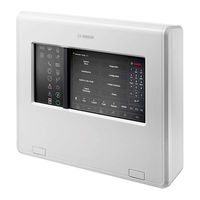
Bosch FPA-1200 User Manual (94 pages)
Brand:
Bosch
| Category:
Control Panel
| Size: 1 MB
Table of Contents
Table of Contents
3
Table of Contents | en
3
Table of Contents | en
5
For Your Safety
7
Operating the Touch Screen
7
Maintenance
7
Usage in Accordance with Regulations
8
Skills Required by Personnel
8
For Your Information
9
What Is New
9
Open Source License Agreement
10
Calling up the Start Menu
10
Changing Language Display
10
Warranty and Liability
10
Copyright
10
All Functions at a Glance
11
In Overview
13
Operating Elements
13
Status Leds
14
Touch Screen
16
Standby Screen
18
Display Support Information
19
Operating Principle
20
Switch on and Switch off
20
Initial Setup
21
Logging on and off
22
Logging on
22
Logging off
22
Access Authorization
22
Calling up the Start Menu
23
Personalized Menu
23
Selecting the Menu
23
Returning to the Previous Selection
23
Working with Lists
24
Scrolling through Lists
25
Various States of List Fields
25
Assigning Mode
26
Search Function/Element
26
Search by Name
26
Searching by Number
27
Entering Numbers and Text
27
Changing an Entry
28
Deleting All Numbers
28
Changing Language Display
28
Entering by Shortcut
28
Change Language by Menu
28
Switching between Status Bars
29
Standby
29
Logical and Physical Addressing
29
Diagnostics
30
Networking Via Ethernet
30
IP Settings
30
Remote Keypad
32
Operation and Display
32
Connecting to Remote Panel
32
Alarm
34
Types of Alarm
34
Entry Delays
34
Day and Night Mode
35
Alarm Message to the Panel
36
Optical and Acoustic Signals
36
Displaying the Detector Zones in Alarm State
36
Sequence of the Alarm Messages
37
Information about Logical Zones in the Alarm State
37
The Newest Message
38
Displaying the Individual Detectors in a Logical Zone
38
Information about Individual Detectors
38
Displaying Additional Information
39
Fire Alarm
40
Evacuation
40
Optical and Acoustic Signals
41
Acknowledging a Message
41
Silence Internal Buzzer
41
Activate and Silence Signaling Devices
41
Resetting Signaling Devices and Transmission Devices
41
Triggering Fire Verification
42
Alarm Verification
42
Starting Time to Investigate
42
Triggering Alarm Manually
43
Resetting Alarm Message
43
Bypassing Detectors
44
Fault Message
45
Calling up Fault Indication
45
Fault Message on the Panel
45
Acknowledging a Message
45
Sequence of the Fault Messages
46
Information about Malfunctioning Element Groups
46
The Newest Message
46
Displaying Individual Elements of an Element Group
47
Information about Individual Elements
47
Displaying Additional Information
47
Signals
48
Resetting Fault Message
48
Blocking an Element
49
Bypass
50
Menu Overview
50
Bypassing and Un-Bypassing Elements
50
Displaying and Un-Bypassing Bypassed Element Groups
50
Via the Status Bar
51
Bypassing/Un-Bypassing Buzzer
51
Displaying List of All Bypassed Elements
51
Using the Menu
51
Bypassing/Un-Bypassing the Output to Fault Warning Routing Equipment
52
Bypassing the Output to Fault Warning Routing Equipment
52
Un-Bypassing the Output to Fault Warning Routing Equipment
52
Block
54
Menu Overview
54
Blocking and Unblocking Elements
54
Displaying List of All Blocked Elements
54
Using the Menu
54
Via the Status Bar
55
Diagnostics
56
Menu Overview
56
Element Details
56
Modules
57
Hardware
57
Display
57
CAN-Bus
58
Panel Passport
58
LED Test on Modules
58
Network Services
58
Routing Table
58
Consistency Check
59
Ethernet Ports
59
Send Ping Command
60
Remote Services
60
Voice Alarm Systems
61
Maintenance
63
Menu Overview
63
Change Language
63
Activate Outputs
63
Activate Transmission Device
64
Bypassing/Un-Bypassing Buzzer
64
Maintenance - Walktest
65
Walktest Groups
65
Adding or Deleting Elements
65
Starting and Ending Walktest
67
Starting the Walktest
67
Ending the Walktest
68
Ending Walktest for All Elements
68
Displaying Tested or Untested Elements
68
Assigning Tested Elements to a Walktest Group
68
Maintenance - History Log
69
Selecting Filters
69
Setting Filters
69
Change Filter
70
Combining Several Filters
70
Status Bar Functions
70
Printing out Data
70
Day and Night Mode
72
Switching between Day and Night Mode
72
Showing Details
73
Changing the Time for Resetting to Night Mode
73
Configuration
75
Menu Overview
75
Physical Node Address (PNA/RSN)
75
Group Setting
75
Adding or Deleting
75
Change Name
77
Detector Sensitivity
77
Operator
77
Change Password
78
Change Universal Password
78
Set Default Password
78
Rename Elements
78
Network Services
79
Ethernet
79
Change Date/Time
79
Remote Services
79
Overview
79
Further Functions
81
Menu Overview
81
Change Date / Time
81
Master Password
81
Enter the Master Password that Is Valid Indefinitely
81
Enter the 24-Hour Master Password
81
Remote Services
82
Change Password
83
Performing a Fire Drill
83
Alarm Counters
84
Reset
85
Menu Overview
85
Resetting Elements
85
Control / Monitor
86
Menu Overview
86
Activate Doorholder, Control Element or HVAC
86
Go to Element
86
Search for Function
86
Boot Menu
88
Index
89
Advertisement
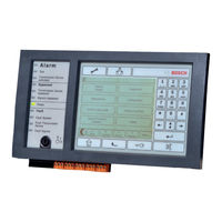
Bosch FPA-1200 Operating Manual (98 pages)
Brand:
Bosch
| Category:
Control Panel
| Size: 3 MB
Table of Contents
Table of Contents
3
Content | en
3
For Your Safety
7
Touch Screen Operation
7
Maintenance
7
Use in Accordance with Standards Knowledge
8
Required for Staff
8
For Your Information
9
What's New
9
Open Source License Agreement
10
Access to the Start Menu
10
Changing the Display Language
10
Warranty and Liability Copyright
10
All Functions at a Glance
12
In Summary
14
Operating Elements Status LED
14
Information Bar
14
Touch Screen
17
Sleep Screen
19
View Support Information
20
Operating Principle Activate
21
And Deactivate
21
Power Button
21
Initial Setup
22
Connection and Disconnection
23
Connection
23
Disconnection
23
Access Authorization
24
Calling the Start Menu
24
Custom Menu
24
Select Menu
24
Return to Previous Selection
25
Working with Lists
25
Scrolling through Lists
26
Navigating through Lists Various States
26
Of List Fields Assign Mode
26
Assign Mode
27
Search Function/Element
27
Search by Name
28
Search by Number
28
Entering Numbers and Text
28
Changing an Entry
29
Quick Introduction
29
Clear All Numbers Change Display
29
Language Enter Via Shortcut Change
29
Delete All Numbers
29
Language Via Menu Switch between
30
Switching between Status Bars
30
Status Bars Sleep
30
Logical and Physical Addressing
30
Network Operation Via Ethernet IP Settings
32
Diagnosis
32
Remote Keyboard
34
Operation and Display Connection
34
To Remote Control Unit
34
Alarm
36
Types of Alarm
36
Entry Delays
36
Day and Night Modes Alarm
37
Message to the Central Unit Optical
38
And Acoustic Signals
38
Display of Detector Zones in Alarm State Alarm Message
39
Sequence
39
Information about Logical Zones in the State of Alarm the
40
Newest Message
40
Viewing Individual Detectors in a Logical Zone Information about
41
Individual Detectors Viewing Additional Information
41
Fire Alarm
43
Muting the Internal Buzzer
44
Activating and Silencing Signaling Devices Resetting Signaling
44
Equipment and Transmitting Equipment Activating Alarm Verification
44
Optical and Acoustic Signals
44
Acknowledgement of a Message
44
Acknowledging a Message
44
Alarm Verification
45
Start of Investigation Time Manual
45
Alarm Trigger
46
Resetting an Alarm Message
46
Bypassing Detectors
47
Error Message
48
Fault Indication Call Fault Message
48
In the Control Panel
48
Acknowledgement of a Message
48
Sequence of Fault Messages
49
Information about Malfunctioning Item Groups the Newest
49
Message
50
Displaying Individual Items in a Group of Items Information about
50
Individual Items
50
Displaying Additional Information Signs
50
Reset the Fault Message
51
Blocking an Element
52
Annulment
53
Menu Summary
53
Cancellation and Uncancellation of Elements
53
Viewing and Un-Un
53
Using the Menu
54
Using the Status Bar Cancel/Uncancel the
54
Buzzer
54
Cancelling/Uncancelling Output to a Fault Notification Routing Device Cancelling
55
Uncancelling Output to a Fault Notification Routing Device Cancelling Output to a Fault
55
Notification Routing Device
55
Block
57
Menu Summary
57
Locking and Unlocking Items
57
Viewing the List of All Blocked Items Using the Menu
57
Using the Status Bar
58
Diagnosis
59
Menu Summary
59
Item Details
59
Modules
60
Hardware
60
Screen
60
CAN Bus
61
Central Passport Module LED
61
Test Network Services
61
Routing Table
62
Consistency Check
62
Ethernet Ports
63
Send Ping Command
63
Remote Services
63
Voice Alarm Systems
65
Maintenance
67
Menu Summary
67
Change Language
67
Activation of Outputs
67
Activating Transmitting Equipment
68
Cancelling/Uncancelling the Buzzer
68
Maintenance - Test
69
Test Groups
69
Adding or Deleting Items. Starting
69
Tilting Function
70
And Ending the Test Starting the
71
Test
71
End of Test
71
Completing Testing for All Items Viewing Tested and Untested
72
Items Assigning Tested Items to a Test Group
72
Maintenance - Historical
73
Filter Selection
73
Filter Settings Filter
73
Filter Change
74
Combining Multiple Filters Status
74
Bar Functions Printing Data
74
Status Bar Functions
74
Day and Night Modes
76
Switching between Day Mode and Night
76
Mode Viewing Details
77
Time Change to Switch to Night Mode
77
Configuration
79
Menu Summary
79
Physical Node Address (PNA/RSN)
79
Group Edit
79
Add or Delete
79
Name Change
81
Detector Sensitivity User
81
Change Password
82
Change Universal Password Set Default
82
Password Rename Items
82
Network Services
83
Rename Elements
83
Ethernet
83
Change Date/Time
83
Remote Services
83
Summary
84
Other Functions
85
Menu Summary
85
Change Date/Time Master
85
Password
85
Enter a Master Password that Is Valid Indefinitely Entering the 24-Hour
85
Master Password
85
Remote Services
86
Change Password
87
Carrying out a Fire Evacuation Alarm Counters
87
Restore
89
Menu Summary
89
Resetting Items
89
Control/Monitor
90
Menu Summary
90
Activate Retainer, Control Element or HVAC Go to
90
Element
90
Search Function
91
Boot Menu
92
Index
93
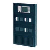
Bosch FPA-1200 System Information (174 pages)
Modular Fire Panel
Brand:
Bosch
| Category:
Fire Alarms
| Size: 22 MB
Table of Contents
Table of Contents
3
Notes
6
Product Description
6
FPA-1200 Fire Panel and FPA-5000 Fire Panel with Functional Modules
6
Panel Controller
11
MPC Panel Controller
11
FPE-8000-SPC | FPE-8000-PPC | FPE-2000-SPC | FPE-2000-PPC Panel Controller
13
Remote Keypad
16
FMR-5000-C Remote Keypad
16
FPE-8000-FMR Remote Keypad
16
Housings for Frame Installation
18
Housings for Wall Mounting
21
System Overview
22
Networking
27
Connection to bis
27
Connecting a Voice Alarm System
27
Planning
28
General Information
28
Detection Points
29
Address Setting
30
Topologies in Local Security Network
31
Failure Handling in Local Security Network
33
Redundancy
34
Achievable Cable Length with LSN 0300 a
36
Achievable Cable Length with LSN 1500 a
38
Examples of Housing Equipment
42
Configuration of BCM Battery Controller Module
43
Protective Earth and Equipotential Bonding
47
Installation
47
General Information
47
Quick Installation Guide
48
Installation of Housing Components
49
Installation Instructions for Housing
50
Installation Dimensions for Wall Mounting Housing
52
Installation Dimensions for Frame Installation Housing
58
Installation Dimensions for Mounting Frames
61
Installation Kits for 48 CM (19") Racks
64
Accessories for Housing
66
RLE 0000 a Junction Board
66
HMP 0003 a Mounting Plate for Mounting Frame
68
FPO-5000-EB Earth Bar
70
Power Supply Brackets
70
FPO-5000-PSB-CH Power Supply Bracket
72
FPO-5000-PSB1 Power Supply Bracket
76
UPS 2416 a Universal Power Supply 24 V/6 a
77
Panel Rails
83
PRS-0002-C Panel Rail Short for 2 Modules
83
PRD 0004 a Panel Rail Long for 4 Modules
85
Panel Rail Installation
86
MPC Panel Controller
89
Functional Modules
100
Installation and Removal
100
ANI 0016 a Annunciator Module
101
BCM-0000-B Battery Controller Module
101
CZM 0004 a 4 Zone Conventional Module
106
ENO 0000 B Fire Service Interface Module
107
FPE-5000-UGM Interface Module
108
IOP 0008 a Input/Output Module
109
IOS 0020 a 20 Ma Communication Module
110
IOS 0232 a RS232 Communication Module
111
LSN 0300 a LSN Improved Module 300 Ma
112
LSN 1500 a LSN Improved Module 1500 Ma
113
NZM 0002 a Notification Appliance Zone Module
115
RMH 0002 a Relay Module for Mains Voltage
116
RML 0008 a Relay Module for Low Voltage
117
Accessories for Functional Modules
118
Cable Sets
119
Extended Line Monitoring (Vds 2540, Vds 2543)
120
FPP-5000 External Power Supply Unit Kit 24 V/6 a
120
THP 2020 a Thermal Printer
122
Remote Keypad
126
Commissioning
141
Notes
141
Documentation
141
Quick Guide for Commissioning
141
Functional Test
141
Preparation
141
Testing the Power Supply
142
Testing the Conventional and LSN Functions
142
Testing the Addressing/Activation
143
Maintenance and Service
143
Warranty
143
Repair
143
Disposal
143
Additional Documentation
143
Technical Data
144
System Limits
144
Power Loss of Components
145
Housing and Accessories
146
Housings for Frame Installation
146
Housings for Wall Mounting
146
PRS-0002-C Panel Rail Short for 2 Modules
147
PRD 0004 a Panel Rail Long for 4 Modules
147
FPO-5000-PSB1/FPO-5000-PSB-CH Power Supply Brackets
147
UPS 2416 a Universal Power Supply 24 V/6 a
148
Panel Controller and Remote Keypad
148
Mpc
148
Remote Keypad
149
Advertisement
Bosch FPA-1200 Networking Manual (66 pages)
Modular fire panel
Brand:
Bosch
| Category:
Fire Alarms
| Size: 21 MB
Table of Contents
Table of Contents
3
Safety
5
Organizational Measures for PC Running Service Clients
5
Explanations of Safety Symbols
6
Safety Notices
6
Introduction
7
System Overview
8
Topologies
9
CAN Loop
14
Ethernet Loop
14
Ethernet Loop with OPC Server
14
Ethernet Loop with OPC Server to Redundant Panel
15
Ethernet/Can Double Loop
15
CAN Loop with Ethernet Segments
15
Ethernet Backbone with Sub-Loops (Ethernet/Can)
16
Connecting Ethernet Loops
17
Ethernet Network
19
Protocols
19
Network Diameter
20
Cables Used
22
Creating or Modifying an Ethernet Network
23
CAN Network
24
Creating or Modifying a CAN Network
25
Ethernet and CAN Networking Pattern
26
Panel Network over Ethernet
26
Panel Network over CAN
26
Connect Services to Panel
27
Panel Network over Ethernet with Redundant Panels
27
Panel Network over CAN with Redundant Panels
28
Panel Network over Two Ethernet Loops
28
Panel Network over Two Ethernet Loops with Redundant Panels
28
Connect Ethernet and CAN Network with Redundant Panels
29
Connect Remote Services to Redundant Panels
29
Remote Services
29
Remote Connect
30
Remote Alert
32
Remote Maintenance
32
Remote Portal
34
Voice Alarm Systems
36
Installation
37
Settings on Media Converter
38
Installing Ethernet Switch
39
Settings on Switch
39
Assign IP Address
40
Program Redundancy Settings
40
Programming the Fault Relay
41
Programming Connection Monitoring
41
Qos Priority, Only for UGM-2040
42
Activating IGMP Snooping
42
Cabling
49
Media Converter
50
Ethernet Switch
51
Remote Keypad
54
FSP-5000-RPS Settings
56
Switches
57
UGM-2040 Servers
58
Appendix
59
Index
61
Advertisement
Related Products
Bosch FPA-1000-UL
Bosch FPA-1000-V2
Bosch FPA-1000 Series
Bosch FPC-500-2
Bosch FPC-500-4
Bosch FPC-500-8
Bosch FPC-500
Bosch FAH-420
Bosch FMC-300RW-GSGYE
Bosch FAP-DOTC420
Bosch Categories
Dishwasher
Washer
Oven
Power Tool
Dryer
More Bosch Manuals
Login
Sign In
OR
Sign in with Facebook
Sign in with Google
Upload manual
Upload from disk
Upload from URL