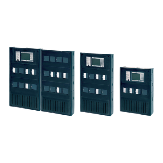
Bosch FPA-5000 System Description
Modular fire panel
Hide thumbs
Also See for FPA-5000:
- Wiring manual (326 pages) ,
- System information (174 pages) ,
- System information manual (170 pages)
Table of Contents
Advertisement
Advertisement
Table of Contents

Related Manuals for Bosch FPA-5000


Summary of Contents for Bosch FPA-5000
- Page 1 Modular Fire Panel FPA-5000 System Description...
-
Page 3: Table Of Contents
Product Description FPA-5000 with Functional Modules MPC Panel Controller FMR-5000 Remote Keypad Housings for Frame Installation Housings for Wall Mounting System Overview of FPA-5000 with Peripherals Networking Connection to BIS Connecting a Plena Voice Alarm System Planning General Information Networking... - Page 4 Maintenance and Service Warranty Repair Disposal Additional Documentation Technical Data System Limits Power loss of FPA-5000 Components Housing and Accessories 7.3.1 Housings for Frame Installation 7.3.2 Housings for Wall Mounting 7.3.3 PRS 0002 A Panel Rail Short for 2 Modules 7.3.4...
- Page 5 Power Supply Units, Power Supply Brackets, Batteries A.2.6 Panel Controller/Remote Keypad A.2.7 Functional Modules A.2.8 Cable Sets A.2.9 Thermal Printer A.2.10 CAN/FOC Adapters Special Applications A.3.1 Controlling Extinguishing Systems History Index Bosch Sicherheitssysteme GmbH System Description F.01U.028.089 | 8.0 | 2011.07...
-
Page 6: Safety Instructions
The fire panel may only be installed and commissioned by trained specialist personnel. NOTICE! Have maintenance and inspection work carried out regularly by trained, qualified personnel. Bosch Sicherheitssysteme GmbH recommends a functional and visual inspection at least once a year. NOTICE! –... -
Page 7: Product Description
Product Description FPA-5000 with Functional Modules With its modular design, the FPA-5000 Fire Panel is easily adapted to local circumstances and regulations. Due to the different functional modules, country-specific characteristics are accommodated in the connection just as quickly as the respective alarm protocol. - Page 8 Functional modules Power supply unit Address cards Housing (in this case: HCP 0006 A) Panel controller Panel rail, long Distributor, optional (RLE) Batteries Panel rail, short Remote keypad Power supply bracket F.01U.028.089 | 8.0 | 2011.07 System Description Bosch Sicherheitssysteme GmbH...
- Page 9 Modular Fire Panel Product Description | en Functions Due to its modular structure, the FPA-5000 Modular Fire Panel provides complete flexibility and thus customized solutions for any application. The configuration of the components is supported by our Fire Systems Designer (FSD) during the planning phase.
- Page 10 (e.g. in terms of cable length and power supply). NOTICE! The Bosch planning software for fire alarm systems enables the system dimensions, the energy requirements and the quantity and prices of the elements required to be estimated at each different phase in the planning process.
-
Page 11: Mpc Panel Controller
11 LEDs provide continuous information about the operating status of the panel or system. Additional LED indicator modules each with 16 detection points can be used to provide visual indication of alarms or faults. Bosch Sicherheitssysteme GmbH System Description F.01U.028.089 | 8.0 | 2011.07... - Page 12 Installation Information on installing the panel controller can be found in Section 4.8 MPC Panel Controller, page 90. The technical data can be found in Section 7.4.1 MPC, page 158. F.01U.028.089 | 8.0 | 2011.07 System Description Bosch Sicherheitssysteme GmbH...
-
Page 13: Fmr-5000 Remote Keypad
Information on installing the Remote Keypad can be found in Section 4.14 FMR-5000 Remote Keypad, page 134. The technical data can be found in Section 7.4.2 FMR-5000 Remote Keypad, page 158. Bosch Sicherheitssysteme GmbH System Description F.01U.028.089 | 8.0 | 2011.07... -
Page 14: Housings For Frame Installation
USF 0000 A Universal Housing Small, Frame Installation. A power supply bracket for a UPS power supply is fitted ex-works in housing units CPH 0006 A, PSF 0002 A and PMF 0004 A. F.01U.028.089 | 8.0 | 2011.07 System Description Bosch Sicherheitssysteme GmbH... - Page 15 FHS 0000 A; this mounting plate can be individually equipped. It contains fixing holes for a distributor rail. The USF 0000 A is fitted with a mounting plate ex works, which can be equipped as required. It contains fixing holes for two distributor rails. Bosch Sicherheitssysteme GmbH System Description F.01U.028.089 | 8.0 | 2011.07...
- Page 16 – FDT 0000 A Front Door Transparent, lock right side – FDT 0003 A Front Door Transparent, lock left side F.01U.028.089 | 8.0 | 2011.07 System Description Bosch Sicherheitssysteme GmbH...
- Page 17 USF 0000 A - Housing, painted sheet steel - Mounting plate The technical data for the frame installation housings can be found in Section 7.3.1 Housings for Frame Installation, page 154. Bosch Sicherheitssysteme GmbH System Description F.01U.028.089 | 8.0 | 2011.07...
-
Page 18: Housings For Wall Mounting
PSS 0002 A or PSB 0004 A Power Supply housings for additional power supply units and 12 V/28 Ah batteries – DIB 0000 A Distribution Box The DIB 0000 A Distribution Box is equipped with a distributor rail and is used to install terminal strips. F.01U.028.089 | 8.0 | 2011.07 System Description Bosch Sicherheitssysteme GmbH... - Page 19 FDT 0001 A HBE 0012 A FDT 0002 A FDT 0001 A The technical data for the housings can be found in Section 7.3.2 Housings for Wall Mounting, page 154. Bosch Sicherheitssysteme GmbH System Description F.01U.028.089 | 8.0 | 2011.07...
-
Page 20: System Overview Of Fpa-5000 With Peripherals
| Product Description Modular Fire Panel System Overview of FPA-5000 with Peripherals Figure 2.7 shows a typical fire detection system design using an FPA-5000 Fire Panel. LSN improved/classic Figure 2.7 System overview of FPA-5000 with peripherals Position Description LSN loop (classic or improved version) - Page 21 Manual call • • points FMC-210-DM • • FMC-210-SM • • FMC-300RW • • FMC-120-DKM • SMF 121 DKM 2014/2-ex • DM 1103 B-Ex • 1) Connection via DCA1192/SB3 only Bosch Sicherheitssysteme GmbH System Description F.01U.028.089 | 8.0 | 2011.07...
- Page 22 • FLM-420-RHV • • FLM-420-RLV1 • • FLM-420-RLV8-S • • FLM-420-I8R1-S • • FLM-420-I2 • • FLM-420-O2 • • FLM-420-O8I2-S • • FLM-420-O1I1 • • FLM-420-RLE-S • FK 100 LSN F.01U.028.089 | 8.0 | 2011.07 System Description Bosch Sicherheitssysteme GmbH...
-
Page 23: Networking
In a loop, two panels can be connected using fiber optic cables via CAN/FOC adapters. The CAN/FOC adapters from Phoenix Contact and EKX are available for this purpose (see Section FOC Networking, page 27). Bosch Sicherheitssysteme GmbH System Description F.01U.028.089 | 8.0 | 2011.07... -
Page 24: Connection To Bis
Connecting a Plena Voice Alarm System The RS232 interface on the IOS 0020 A or IOS 0232 A enables the FPA-5000 to control up to 120 Plena voice alarm zones. This control can be defined down to the individual detector level. -
Page 25: Planning
Terminating each stub and each T-tap with EOL modules is essential to set up a complete fire alarm system complying with EN 54-13. – Conventional detectors approved for the FPA-5000 can be connected using one of the following methods: –... - Page 26 Technical Data and System Limits Refer to the system limits in Section 7.1 System Limits, page 152. The technical data for all components can be found in Section 7 Technical Data, page 152. F.01U.028.089 | 8.0 | 2011.07 System Description Bosch Sicherheitssysteme GmbH...
-
Page 27: Networking
The maximum cable length is 700 m. For details on the design and configuration, refer to the technical information: FPA 5000 network via fiber optic converters "Phoenix Contact - PSI-MOS-DNET CAN/FO". This can be found on the "Bosch Security Systems Extranet" at www.boschsecurity.net/extranet. - Page 28 Figure 3.1 Network (redundant bus topology) with a redundant panel (8/8*) NOTICE! The maximum cable length is 1000 m, from the first to the last node. The cable length depends on the cable cross section and the number of nodes. F.01U.028.089 | 8.0 | 2011.07 System Description Bosch Sicherheitssysteme GmbH...
- Page 29 Topology Remark Standalone panel Standalone panel, redundant Loop Max. 32 FPA-5000/FMR-5000 Loop with redundant panel Max. 32 FPA-5000/FMR-5000 + 1 redundant FPA-5000 each Max. 8 FPA-5000/FMR-5000 Bus with redundant panel Max. 8 FPA-5000/FMR-5000 + 1 redundant FPA-5000 each Redundant bus Max.
- Page 30 (see Figure 3.2). Figure 3.2 Achievable cable length, depending on the number of nodes and the cable resistance cable length in meters number of nodes F.01U.028.089 | 8.0 | 2011.07 System Description Bosch Sicherheitssysteme GmbH...
-
Page 31: Structures In Local Security Network
When configuring the detectors, it is essential to ensure that no mesh structures are created. FPA-5000 FPA-5000 Mesh structures within a stub structure Mesh structures within a loop structure Table 3.3 Unusable network structures Bosch Sicherheitssysteme GmbH System Description F.01U.028.089 | 8.0 | 2011.07... -
Page 32: Detection Points
Detection Points Each element or input that can trigger an alarm after programming requires its own detection point. Detection points are enabled via address cards. One FPA-5000 manages up to 4096 detection points. All elements and inputs that do not use the "Input" type in the "Message type" setting are regarded as detection points. -
Page 33: Addressing
Note that structures with T-tapping are only possible if only LSN improved elements are used (see Section 3.3 Structures in Local Security Network, page 31). For setting addresses with DIP switches, refer to the instructions in the installation guide supplied with the products. Bosch Sicherheitssysteme GmbH System Description F.01U.028.089 | 8.0 | 2011.07... -
Page 34: Achievable Cable Length With Lsn 0300 A
Y axis at 1000, go horizontally across to the right as far as the 20 mA curve and then from the point of intersection vertically down to the X axis. Read off the maximum number of network elements, in this example it is 8. F.01U.028.089 | 8.0 | 2011.07 System Description Bosch Sicherheitssysteme GmbH... - Page 35 Figure 3.3 Diagram for determining the maximum achievable cable length: LSN classic elements with LSN 0300 A cable length in meters number of LSN classic elements 1600 m limit 300 mA limit maximum possible number of LSN classic elements = 127 Bosch Sicherheitssysteme GmbH System Description F.01U.028.089 | 8.0 | 2011.07...
- Page 36 Figure 3.4 Diagram for determining the maximum achievable cable length: LSN improved elements with LSN 0300 A cable length in meters number of LSN improved elements 1600 m limit bus dynamic limit maximum possible number of LSN improved elements = 254 300 mA limit F.01U.028.089 | 8.0 | 2011.07 System Description Bosch Sicherheitssysteme GmbH...
-
Page 37: Achievable Cable Length With Lsn 1500 A
A maximum additional cable length of 500 m is allowed when using remote displays (e.g. MPA/FAA-420-RI). The total length of installed cable must not exceed the limit of 3000 m. Bosch Sicherheitssysteme GmbH System Description F.01U.028.089 | 8.0 | 2011.07... - Page 38 Figure 3.5 Diagram for determining the maximum achievable cable length: LSN classic elements with LSN 1500 A cable length in meters number of LSN classic elements 3000 m limit maximum possible number of LSN classic elements = 127 F.01U.028.089 | 8.0 | 2011.07 System Description Bosch Sicherheitssysteme GmbH...
- Page 39 Figure 3.6 Diagram for determining the maximum achievable cable length: LSN improved elements with LSN 1500 A cable length in meters number of LSN improved elements Bus dynamic limit maximum possible number of LSN improved elements = 254 Bosch Sicherheitssysteme GmbH System Description F.01U.028.089 | 8.0 | 2011.07...
-
Page 40: Examples Of Housing Equipment
FBH 0000 A / FHS 0000 A HMP 0003 A 12 V / 45 Ah 12 V / 45Ah Figure 3.7 Example of configuration with CPH 0006 A frame installation housing for 6 modules F.01U.028.089 | 8.0 | 2011.07 System Description Bosch Sicherheitssysteme GmbH... - Page 41 HCP 0006 A FPO-5000-PSB-CH 12 V / 28 Ah 12 V / 28 Ah UPS 2416 A Figure 3.8 Example of configuration with HCP 0006 A Modular Panel Housing for 6 Modules Bosch Sicherheitssysteme GmbH System Description F.01U.028.089 | 8.0 | 2011.07...
-
Page 42: Configuration Of Bcm Battery Controller Module
The cables for the switch outputs for faults may only be routed inside the housing. Information on installation of the BCM module can be found in Section 4.9.3 BCM-0000-B Battery Controller Module, page 110. F.01U.028.089 | 8.0 | 2011.07 System Description Bosch Sicherheitssysteme GmbH... - Page 43 12 V / 28 Ah 12 V / 28 Ah 12 V / 28 Ah 12 V / 28 Ah Figure 3.9 Configuration of 1 to 4 BCM modules (wall mounting) Bosch Sicherheitssysteme GmbH System Description F.01U.028.089 | 8.0 | 2011.07...
- Page 44 12 V / 45 Ah 12 V / 45 Ah 12 V / 45 Ah 12 V / 45 Ah Figure 3.10 Configuration of 1 to 4 BCM modules (frame installation) F.01U.028.089 | 8.0 | 2011.07 System Description Bosch Sicherheitssysteme GmbH...
- Page 45 12 V / 24 Ah 12 V / 24 Ah 12 V / 24 Ah 12 V / 24 Ah Figure 3.11 Configuration of 5 to 8 BCM modules (wall mounting) Bosch Sicherheitssysteme GmbH System Description F.01U.028.089 | 8.0 | 2011.07...
- Page 46 Batt Possible capacities (CBatt): – 24 - 26 Ah or 36 - 45 Ah with 2 batteries – 48 - 52 Ah or 72 - 90 Ah with 4 batteries F.01U.028.089 | 8.0 | 2011.07 System Description Bosch Sicherheitssysteme GmbH...
-
Page 47: Redundancy
Interface Module – The redundant connection of the transmission device (TD or AT 2000) in line with the connections as described in the FPA-5000/FPA-1200 wiring guide (document number F.01U.009.201) – Activation of extinguishing systems in accordance with VdS 2496: If a signal processing unit fails, no more than one extinguishing area may fail. - Page 48 10 modules and three housings each with 12 modules. NOTICE! In line with EN 54-2, a redundant panel controller must be used if there are more than 512 detectors connected. F.01U.028.089 | 8.0 | 2011.07 System Description Bosch Sicherheitssysteme GmbH...
-
Page 49: Installation
– The fire panel may only be installed and commissioned by trained specialist personnel. – Only use installation materials recommended by BOSCH Security Systems. Otherwise, interference resistance cannot be guaranteed. – Connection conditions set down by the regional authorities and institutions (police, fire service) must be observed. - Page 50 The current and full product documentation can also be found on the Internet at www.boschsecurity.com. – For those with access rights, the current wiring guide can be found on the "Bosch Security Systems Extranet" at http://www.boschbest.de. This contains information about the wiring of the functional modules and the peripherals.
-
Page 51: Quick Installation Guide
Mounting frames – Housing – Optional: accessories for housing – Power supply unit and batteries – Panel rail – Panel controller – Functional modules 4. After installation Store all documents. Bosch Sicherheitssysteme GmbH System Description F.01U.028.089 | 8.0 | 2011.07... -
Page 52: Installation Of Housing Components
At the marked points, drill holes approx. 55 mm deep with an 8-mm drill. Insert a dowel in each hole. 10. Refit the FSH 0000 A Mounting Frame, as described in step 6. 11. Screw the FSH 0000 A Mounting Frame tight. F.01U.028.089 | 8.0 | 2011.07 System Description Bosch Sicherheitssysteme GmbH... -
Page 53: Installation Instructions For Housing
PSF 0002 A and USF 0000 A Wall Mounting Panel housings for wall mounting Document number HCP 0006 A Modular panel housing for 6 modules 4.998.153.981 HBC 0010 A Modular panel housing for 10 modules 4.998.153.995 Bosch Sicherheitssysteme GmbH System Description F.01U.028.089 | 8.0 | 2011.07... - Page 54 FDT 0001 A Front door, transparent, large, lock right side F.01U.003.100 FDT 0002 A Front door, transparent, large, lock left side F.01U.003.104 FDT 0003 A Front door, transparent, lock left side F.01U.003.102 F.01U.028.089 | 8.0 | 2011.07 System Description Bosch Sicherheitssysteme GmbH...
-
Page 55: Installation Dimensions For Wall Mounting Housing
Installation | en 4.3.2 Installation Dimensions for Wall Mounting Housing HPC 0006 A Modular Panel Housing for 6 Modules 12,5 Figure 4.2 Installation dimensions - HCP 0006 A [in mm] Bosch Sicherheitssysteme GmbH System Description F.01U.028.089 | 8.0 | 2011.07... - Page 56 | Installation Modular Fire Panel HBC 0010 A Modular Panel Housing for 10 Modules 12,5 Figure 4.3 Installation dimensions - HBC 0010 A [in mm] F.01U.028.089 | 8.0 | 2011.07 System Description Bosch Sicherheitssysteme GmbH...
- Page 57 Modular Fire Panel Installation | en HBE 0012 A Modular Extension Housing for 12 Modules 12,5 Figure 4.4 Installation dimensions - HBE 0012 A [in mm] Bosch Sicherheitssysteme GmbH System Description F.01U.028.089 | 8.0 | 2011.07...
- Page 58 | Installation Modular Fire Panel PSB 0004 A Power Supply Module, Wall Mounting 12,5 Figure 4.5 Installation dimensions - PSB 0004 A [in mm] F.01U.028.089 | 8.0 | 2011.07 System Description Bosch Sicherheitssysteme GmbH...
- Page 59 Modular Fire Panel Installation | en PSS 0002 A Power Supply Small/DIB 0000 A Distribution Box 12,5 Figure 4.6 Installation dimensions - PSS 0002 A/DIB 0000 A [in mm] Bosch Sicherheitssysteme GmbH System Description F.01U.028.089 | 8.0 | 2011.07...
- Page 60 When inserting the cable into the housing, pierce a hole in the grommet with a pointed object, do not cut. HCP 0006 A HBC 0010 A HBE 0012 A PSB 0004 A PSS 0002 A Figure 4.7 Wall mounting housing cable bushings F.01U.028.089 | 8.0 | 2011.07 System Description Bosch Sicherheitssysteme GmbH...
-
Page 61: Installation Dimensions For Frame Installation Housing
Installation Dimensions for CPH 0006 A, EPH 0012 A and MPH 0010 A with FBH 0000 A or FHS 0000 A Mounting Frames 15,5 452,5 455,5 Figure 4.8 Installation dimensions for CPH 0006 A, EPH 0012 A and MPH 0010 A [in mm] Bosch Sicherheitssysteme GmbH System Description F.01U.028.089 | 8.0 | 2011.07... - Page 62 | Installation Modular Fire Panel Installation Dimensions for PMF 0004 A with FMH 0000 A Mounting Frame 15,5 452,5 455,5 Figure 4.9 Installation dimensions for PMF 0004 A [in mm] F.01U.028.089 | 8.0 | 2011.07 System Description Bosch Sicherheitssysteme GmbH...
- Page 63 Installation Dimensions for PSF 0002 A and USF 0000 A with FSH 0000 A Mounting frame 15,5 452,5 455,5 Figure 4.10 Installation dimensions for PSF 0002 A and USF 0000 A [in mm] Bosch Sicherheitssysteme GmbH System Description F.01U.028.089 | 8.0 | 2011.07...
-
Page 64: Installation Dimensions For Mounting Frames
Modular Fire Panel 4.3.4 Installation Dimensions for Mounting Frames FBH 0000 A/FHS 0000 A Mounting Frame Large 290 ± 0,5 Figure 4.11 Installation dimensions - FBH 0000 A/FHS 0000 A [in mm] F.01U.028.089 | 8.0 | 2011.07 System Description Bosch Sicherheitssysteme GmbH... - Page 65 290 ± 0,5 Figure 4.12 Installation dimensions - FMH 0000 A [in mm] FSH 0000 A Mounting Frame Small 290 ± 0,5 Figure 4.13 Installation dimensions - FSH 0000 A [in mm] Bosch Sicherheitssysteme GmbH System Description F.01U.028.089 | 8.0 | 2011.07...
-
Page 66: Installation Kits For 482.6 Mm (19") Racks
DIB 0000 A 217 mm PSB 0004 A 308 mm HCP 0006 A 409 mm HBC 0010 A 609 mm HBE 0012 A 609 mm Figure 4.14 FRK 0019 A housing installation F.01U.028.089 | 8.0 | 2011.07 System Description Bosch Sicherheitssysteme GmbH... - Page 67 267 x 449 x 233.5 mm FRB 0019 A Rack Installation Kit, Large Figure 4.15 FRB 0019 A installation kit for CPH 0006 A, MPH 0010 A, EPH 0012 A [installation dimensions in mm] Bosch Sicherheitssysteme GmbH System Description F.01U.028.089 | 8.0 | 2011.07...
- Page 68 Figure 4.17 FRS 0019 A installation kit for PSF 0002 A, USF 0000 A [installation dimensions in mm] The FRS 0019 A installation kit is also used for the THP 2020 A Thermal Printer. F.01U.028.089 | 8.0 | 2011.07 System Description Bosch Sicherheitssysteme GmbH...
-
Page 69: Accessories For Housing
The RLE 0000 A junction board is also required to connect the AT 2000 transmission device. RLE 0000 A M3 x 10 Figure 4.18 RLE 0000 A installation Bosch Sicherheitssysteme GmbH System Description F.01U.028.089 | 8.0 | 2011.07... -
Page 70: Hmp 0003 A Mounting Plate For Mounting Frame
It can be fitted with a distributor rail. NOTICE! The distributor rail is not included in the scope of delivery for the HMP 0003 A Mounting Plate. Figure 4.20 HMP 0003 A installation F.01U.028.089 | 8.0 | 2011.07 System Description Bosch Sicherheitssysteme GmbH... -
Page 71: Fpo-5000-Eb Earth Bar
The FPO-5000-EB Earth Bar is inserted in the FMH 0000 A Mounting Frame Medium in a prefabricated bracket. It allows star grounding of a centrally positioned extension housing. ∅ 4 x 12 mm FMH 0000 A FPO-5000-EB Figure 4.21 FPO-5000-EB installation Bosch Sicherheitssysteme GmbH System Description F.01U.028.089 | 8.0 | 2011.07... -
Page 72: Power Supply Brackets
All frame installation housings designed for a power supply bracket are supplied with one of these brackets, which is fitted ex works. NOTICE! A maximum of one power supply bracket and one power supply can be installed in the power supply housing. F.01U.028.089 | 8.0 | 2011.07 System Description Bosch Sicherheitssysteme GmbH... - Page 73 Modular Fire Panel Installation | en M4 x 12 mm Figure 4.22 FPO-5000-PSB-CH/FPO-5000-PSB1 installation (1-4) Bosch Sicherheitssysteme GmbH System Description F.01U.028.089 | 8.0 | 2011.07...
-
Page 74: Fpo-5000-Psb-Ch Power Supply Bracket
The technical data can be found in Section 7.3.5 FPO-5000-PSB1/FPO-5000-PSB-CH Power Supply Brackets, page 156. HCP 0006 A HBC 0010 A HBE 0012 A Figure 4.24 FPO-5000-PSB-CH housing compatibility and installation of temperature sensor F.01U.028.089 | 8.0 | 2011.07 System Description Bosch Sicherheitssysteme GmbH... - Page 75 Modular Fire Panel Installation | en M4 x 12 mm Figure 4.25 FPO-5000-PSB-CH installation (5-8) Bosch Sicherheitssysteme GmbH System Description F.01U.028.089 | 8.0 | 2011.07...
- Page 76 | Installation Modular Fire Panel 100 - 240 V AC 50 - 60 Hz T 10 A / 250 V L1 G Figure 4.26 FPO-5000-PSB-CH installation (9) F.01U.028.089 | 8.0 | 2011.07 System Description Bosch Sicherheitssysteme GmbH...
-
Page 77: Fpo-5000-Psb1 Power Supply Bracket
The FPO-5000-PSB1 Power Supply Bracket is used in the PSS 0002 A and PSB 0004 A power supply housings. It is installed in a central position between two batteries. The technical data can be found in Section 7.3.5 FPO-5000-PSB1/FPO-5000-PSB-CH Power Supply Brackets, page 156. Bosch Sicherheitssysteme GmbH System Description F.01U.028.089 | 8.0 | 2011.07... - Page 78 | Installation Modular Fire Panel M4 x 12 mm 100 - - 240 V ∼ ∼ 50 - - 60 Hz Figure 4.28 FPO-5000-PSB1 installation (5-9) F.01U.028.089 | 8.0 | 2011.07 System Description Bosch Sicherheitssysteme GmbH...
-
Page 79: Ups 2416 A Universal Power Supply 24 V/6 A
UPS 2416 A Universal Power Supply 24 V/6 A The UPS 2416 A is a plug-and-play switching power supply that provides the power for the FPA-5000 Fire Panel. It is inserted into a power supply bracket and is then ready to use immediately. - Page 80 UPS 2416 A ⇒ FPO-5000-PSB1 MAIN POWER TROUBLE BATTERY 1 TROUBLE BATTERY 2 TROUBLE 24 V BCM-0000-B UPS 2416 A Figure 4.30 Installation of UPS 2416 A in FPO-5000-PSB1 (1) F.01U.028.089 | 8.0 | 2011.07 System Description Bosch Sicherheitssysteme GmbH...
- Page 81 Modular Fire Panel Installation | en UPS 2416 A ⇒ FPO-5000-PSB1 Figure 4.31 Installation of UPS 2416 A in FPO-5000-PSB1 (2-5) Bosch Sicherheitssysteme GmbH System Description F.01U.028.089 | 8.0 | 2011.07...
- Page 82 Only one power supply unit can be installed in the FPO-5000-PS-CH Power Supply Bracket (see Figure 4.32). UPS 2416 A ⇒ FPO-5000-PSB-CH Figure 4.32 Installation of UPS 2416 A in FPO-5000-PS-CH (1-4) F.01U.028.089 | 8.0 | 2011.07 System Description Bosch Sicherheitssysteme GmbH...
- Page 83 Each power supply unit and each housing comes with a self-adhesive product label. Attach the sticker to the outside of the housing (see Figure 4.33). Figure 4.33 Attaching the stickers Bosch Sicherheitssysteme GmbH System Description F.01U.028.089 | 8.0 | 2011.07...
-
Page 84: Panel Rails
+24 V +5 V Figure 4.34 PRS 0002 A connections The technical data can be found in Section 7.3.3 PRS 0002 A Panel Rail Short for 2 Modules, page 154. F.01U.028.089 | 8.0 | 2011.07 System Description Bosch Sicherheitssysteme GmbH... - Page 85 Modular Fire Panel Installation | en CPH 0006 A MPH 0010 A HCP 0006 A HBC 0010 A Figure 4.35 PRS 0002 A installation Bosch Sicherheitssysteme GmbH System Description F.01U.028.089 | 8.0 | 2011.07...
- Page 86 | Installation Modular Fire Panel Figure 4.36 Connection of PRS 0002 A F.01U.028.089 | 8.0 | 2011.07 System Description Bosch Sicherheitssysteme GmbH...
-
Page 87: Prd 0004 A Panel Rail Long For 4 Modules
CANH CANL +24V 120Ω Figure 4.37 PRD 0004 A connections The technical data can be found in Section 7.3.4 PRD 0004 A Panel Rail Long for 4 Modules, page 156. Bosch Sicherheitssysteme GmbH System Description F.01U.028.089 | 8.0 | 2011.07... - Page 88 | Installation Modular Fire Panel CPH 0006 A MPH 0010 A EPH 0012 A HCP 0006 A HBC 0010 A HBE 0012 A Figure 4.38 PRD 0004 A installation F.01U.028.089 | 8.0 | 2011.07 System Description Bosch Sicherheitssysteme GmbH...
- Page 89 Modular Fire Panel Installation | en Figure 4.39 Connection of PRD 0004 A Bosch Sicherheitssysteme GmbH System Description F.01U.028.089 | 8.0 | 2011.07...
-
Page 90: Mpc Panel Controller
Please refer to Figure 4.40 for the scope of delivery. The enclosed CD contains the FSP-5000-RPS programming software, as well as product documentation for the FPA-5000, including operating instructions. The technical data can be found in Section 7.4.1 MPC, page 158. - Page 91 Two switch positions, freely programmable, e.g. for switching between day/night mode or activating/ deactivating local alarms 3 rotary switches Address setting Reboot button Panel hardware reset 6-pin DIP switch Configuration setting Grounding cable Panel controller grounding Bosch Sicherheitssysteme GmbH System Description F.01U.028.089 | 8.0 | 2011.07...
- Page 92 Section Addressing and Settings in the Network, page 99. USB Device RS232 max. 3 m max. 3 m Figure 4.42 MPC, USB and RS232 interfaces Ethernet Server 100BaseTX FPA-5000 Figure 4.43 MPC connection to BIS via OPC server F.01U.028.089 | 8.0 | 2011.07 System Description Bosch Sicherheitssysteme GmbH...
- Page 93 Plug the terminal element for the data bus into the "OUT" slot on the last occupied PSD/ PRD panel rail (step 8 in Figure 4.46). PRS 0002 A Figure 4.44 MPC installation (1-3) Bosch Sicherheitssysteme GmbH System Description F.01U.028.089 | 8.0 | 2011.07...
- Page 94 | Installation Modular Fire Panel MPC-xxxx-B / FPA-1200-MPC PRS 0002 A PRD 0004 A Figure 4.45 MPC installation (4-6) F.01U.028.089 | 8.0 | 2011.07 System Description Bosch Sicherheitssysteme GmbH...
- Page 95 Modular Fire Panel Installation | en Figure 4.46 MPC installation (7-9) Bosch Sicherheitssysteme GmbH System Description F.01U.028.089 | 8.0 | 2011.07...
- Page 96 Each module, each monitored module input and each LSN element occupies a detection point (an address). – An FPA-5000 can manage up to 4096 addresses. A detailed explanation of addresses and detection points can be found starting on Section 3.4 Detection Points, page 32.
- Page 97 1024 1024 2048 OPC 4096 2048 2048 2048 2048 8192 2048 2048 OPC 4608 1024 2048 2048 OPC 5120 2048 2048 2048 OPC 6144 Figure 4.48 Address Cards ADC xxxx A Bosch Sicherheitssysteme GmbH System Description F.01U.028.089 | 8.0 | 2011.07...
- Page 98 ADC-5000-OPC License Key The ADC-5000-OPC License Key is a special address card that enables communication between the OPC server and an FPA-5000 Modular Fire Panel. The OPC server connects the fire panel to a building management system (BIS). Although all the panels in a network can be connected to the OPC server, the license key only needs to be fitted to one of them.
- Page 99 The DIP switches are located on the rear of the panel controller (see Figure 4.50). Mark the selected setting on the sign above the DIP switches (see Figure 4.50, step 4). NOTICE! Redundant panels must have identical addresses. Bosch Sicherheitssysteme GmbH System Description F.01U.028.089 | 8.0 | 2011.07...
- Page 100 Figure 4.50 MPC Panel Controller, addressing GNDIN2 G L H G L H G L H G L H CAN1 CAN1 CAN2 CAN2 Figure 4.51 MPC Panel Controller, network connections F.01U.028.089 | 8.0 | 2011.07 System Description Bosch Sicherheitssysteme GmbH...
- Page 101 CAN1_GND CAN2_GND Connection Connection Connection PCTRL is PCTRL is PCTRL is Redundant-PCTRL No Off Redundant-PCTRL Redundant-PCTRL No Off No Off Figure 4.52 Standalone panel (regular and redundant): Configuration in network Bosch Sicherheitssysteme GmbH System Description F.01U.028.089 | 8.0 | 2011.07...
- Page 102 CAN1_GND CAN2_GND Connection Connection Connection Connection Connection PCTRL is PCTRL is PCTRL is Redundant-PCTRL Redundant-PCTRL Redundant-PCTRL No Off No Off No Off No Off No Off Figure 4.53 Loop topology F.01U.028.089 | 8.0 | 2011.07 System Description Bosch Sicherheitssysteme GmbH...
- Page 103 Connection Connection Connection Connection PCTRL is PCTRL is PCTRL is Redundant-PCTRL Redundant-PCTRL Redundant-PCTRL No Off No Off No Off No Off No Off Figure 4.54 Loop topology with redundant panel Bosch Sicherheitssysteme GmbH System Description F.01U.028.089 | 8.0 | 2011.07...
- Page 104 CAN1_GND CAN2_GND Connection Connection Connection Connection Connection PCTRL is PCTRL is PCTRL is Redundant-PCTRL Redundant-PCTRL Redundant-PCTRL No Off No Off No Off No Off No Off Figure 4.55 Bus Topology F.01U.028.089 | 8.0 | 2011.07 System Description Bosch Sicherheitssysteme GmbH...
- Page 105 Connection Connection Connection Connection PCTRL is PCTRL is PCTRL is Redundant-PCTRL Redundant-PCTRL Redundant-PCTRL No Off No Off No Off No Off No Off Figure 4.56 Bus topology with redundant panel Bosch Sicherheitssysteme GmbH System Description F.01U.028.089 | 8.0 | 2011.07...
- Page 106 Connection Connection Connection Connection PCTRL is PCTRL is PCTRL is Redundant-PCTRL Redundant-PCTRL No Off Redundant-PCTRL No Off No Off No Off No Off Figure 4.57 Bus topology with redundant network F.01U.028.089 | 8.0 | 2011.07 System Description Bosch Sicherheitssysteme GmbH...
- Page 107 Connection PCTRL is PCTRL is PCTRL is Redundant-PCTRL Redundant-PCTRL Redundant-PCTRL No Off No Off No Off No Off No Off Figure 4.58 Bus topology with redundant network and redundant panel Bosch Sicherheitssysteme GmbH System Description F.01U.028.089 | 8.0 | 2011.07...
-
Page 108: Functional Modules
Functional settings on the modules are made using the FSP-5000-RPS programming software. 4.9.1 Installation and Removal Figure 4.59 Installation and removal of functional modules F.01U.028.089 | 8.0 | 2011.07 System Description Bosch Sicherheitssysteme GmbH... -
Page 109: Ani 0016 A Annunciator Module
The activation of each LED is defined using the FSP-5000-RPS programming software. This defines which detection points will activate the LEDs in which state. The technical data can be found in Section 7.5.1 ANI 0016 A Annunciator Module, page 159. Bosch Sicherheitssysteme GmbH System Description F.01U.028.089 | 8.0 | 2011.07... -
Page 110: Bcm-0000-B Battery Controller Module
The module can only be used with the MPC Panel Controller from software version 2.1 onwards. – If the FPA-5000 Fire Panel is not supplied with mains power, it can only be started – if a battery pair is connected to BAT1 and –... - Page 111 Modular Fire Panel Installation | en 111 – If the FPA-5000 Fire Panel is not supplied with mains power for an extended period, ensure that the batteries are disconnected. – When using the module in the FPP-5000 External Power Supply, only one battery pair can be charged (see Section 4.12 FPP-5000 External Power Supply Unit Kit 24 V/6 A,...
- Page 112 The temperature sensor is supplied with the power supply bracket and protects the batteries against overheating. If the sensor is not positioned correctly, the batteries can overheat and explode. Position the temperature sensor between the batteries. F.01U.028.089 | 8.0 | 2011.07 System Description Bosch Sicherheitssysteme GmbH...
-
Page 113: Czm 0004 A 4 Zone Conventional Module
The EOL modules can be used with CZM modules from software version 1.1.10 onwards. The technical data can be found in Section 7.5.3 CZM 0004 A 4 Zone Conventional Module, page 160. Bosch Sicherheitssysteme GmbH System Description F.01U.028.089 | 8.0 | 2011.07... -
Page 114: Eno 0000 B Fire Service Interface Module
⊗ + | − Signal lamp, e.g. BEGA lamp +24 V, approx. 10 W Relay 1-4 Information on the redundant connection of the module can be found in Section 3.10 Redundancy, page 47. F.01U.028.089 | 8.0 | 2011.07 System Description Bosch Sicherheitssysteme GmbH... -
Page 115: Fpe-5000-Ugm Interface Module
161. 4.9.6 FPE-5000-UGM Interface Module The interface module allows the FPA-5000 Modular Fire Panel or an FPA-5000/FMR-5000 network to be connected to a higher-level system such as the UGM 2020, FAT-2002/RE or FSM-2000, and provides two bi-directional transmission paths. -
Page 116: Iop 0008 A Input/Output Module
IN1-IN8 Inputs, max. voltage of 5 V DC at 0.1 mA per input Ground The technical data can be found in Section 7.5.6 IOP 0008 A Input/Output Module, page 161. F.01U.028.089 | 8.0 | 2011.07 System Description Bosch Sicherheitssysteme GmbH... -
Page 117: Ios 0020 A 20 Ma Communication Module
Assignment of DSUB 9 Plug Figure 4.70 DSUB 9 plug PIN no. Connection TxD0 RxD0 The technical data can be found in Section 7.5.7 IOS 0020 A 20 mA Communication Module, page 161. Bosch Sicherheitssysteme GmbH System Description F.01U.028.089 | 8.0 | 2011.07... -
Page 118: Ios 0232 A Rs232 Communication Module
Assignment of DSUB 9 Plug Figure 4.72 DSUB 9 plug PIN no. Connection TxD0 RxD0 The technical data can be found in Section 7.5.8 IOS 0232 A RS232 Communication Module, page 162. F.01U.028.089 | 8.0 | 2011.07 System Description Bosch Sicherheitssysteme GmbH... -
Page 119: Lsn 0300 A Lsn Improved Module 300 Ma
* The auxiliary voltage may only be fed back to AUX2 when isolators (ERT technology) are used in the loop (suitable components include YBO-R/SCI isolators). The technical data can be found in Section 7.5.9 LSN 0300 A LSN improved Module 300 mA, page 162. Bosch Sicherheitssysteme GmbH System Description F.01U.028.089 | 8.0 | 2011.07... -
Page 120: Lsn 1500 A Lsn Improved Module 1500 Ma
* The auxiliary voltage may only be fed back to AUX2 when isolators (ERT technology) are used in the loop (suitable components include YBO-R/SCI isolators). The technical data can be found in Section 7.5.10 LSN 1500 A LSN improved Module 1500 mA, page 163. F.01U.028.089 | 8.0 | 2011.07 System Description Bosch Sicherheitssysteme GmbH... - Page 121 LSN 1500 A LSN 1500 A LSN 1500 A PRD 0004 A PRD 0004 A LSN 1500 A LSN 1500 A Figure 4.75 LSN 1500 A - Inserting the module Bosch Sicherheitssysteme GmbH System Description F.01U.028.089 | 8.0 | 2011.07...
-
Page 122: Nzm 0002 A Notification Appliance Zone Module
SYNC GND | SYNC OUT Output synchronization SYNC GND | SYNC IN Input synchronization The technical data can be found in Section 7.5.11 NZM 0002 A Notification Appliance Zone Module, page 163. F.01U.028.089 | 8.0 | 2011.07 System Description Bosch Sicherheitssysteme GmbH... -
Page 123: Rmh 0002 A Relay Module For Mains Voltage
Feedback relay 1 FB2 + | FB2 + Feedback relay 2 The technical data can be found in Section 7.5.12 RMH 0002 A Relay Module for mains voltage, page 164. Bosch Sicherheitssysteme GmbH System Description F.01U.028.089 | 8.0 | 2011.07... -
Page 124: Rml 0008 A Relay Module For Low Voltage
NO7 | C7 | NC7 Relay 7 NO8 | C8 | NC8 Relay 8 The technical data can be found in Section 7.5.13 RML 0008 A Relay Module for Low Voltage, page 164. F.01U.028.089 | 8.0 | 2011.07 System Description Bosch Sicherheitssysteme GmbH... -
Page 125: Accessories For Functional Modules
The strips can be individually printed using a standard laser printer. A dot file is included on the CD supplied with the MPC Panel Controller. Scope of delivery: 20 sheets of 6 strips. Bosch Sicherheitssysteme GmbH System Description F.01U.028.089 | 8.0 | 2011.07... - Page 126 FDP 0001 A Dummy Cover Plate Figure 4.82 FDP 0001 A Dummy Cover Plate Fit the dummy cover plates on unused module slots in the front panels of the housings. F.01U.028.089 | 8.0 | 2011.07 System Description Bosch Sicherheitssysteme GmbH...
-
Page 127: Cable Sets
Use an FLM-320-EOL4W for the conventional zone of a conventional zone module or a FLM-420-CON/4 Activate EN 54-13 compliant operation. NOTICE! According to EN 54-13, no branch wiring (T-tapping) is permitted for auxiliary power supplies. Bosch Sicherheitssysteme GmbH System Description F.01U.028.089 | 8.0 | 2011.07... -
Page 128: Fpp-5000 External Power Supply Unit Kit 24 V/6 A
(document number for installation instructions: F.01U.005.065). – The installation dimensions are the same as those for the PMF 0004 A (see Section Installation Dimensions for PMF 0004 A with FMH 0000 A Mounting Frame). F.01U.028.089 | 8.0 | 2011.07 System Description Bosch Sicherheitssysteme GmbH... - Page 129 You can find the installation instructions for the FPP-5000-TI module at www.boschsecurity.com (document number for installation instructions: F.01U.081.396). The technical data can be found in Section 7.6.2 FPP-5000-TI Trouble Interface, page 165. Bosch Sicherheitssysteme GmbH System Description F.01U.028.089 | 8.0 | 2011.07...
-
Page 130: Thp 2020 A Thermal Printer
If the supply of paper is nearing its end, this is indicated by a message on the display of the control panel. When this message appears, you still have enough paper on the roll to print approx. 200 lines of text. F.01U.028.089 | 8.0 | 2011.07 System Description Bosch Sicherheitssysteme GmbH... - Page 131 Installation | en 131 Printer Settings using Jumpers Notes: – The jumpers BR2, BR3 and BR4 must not be inserted if connecting to the FPA-5000. – Caution: Inserting jumper BR1 changes the character set from Western to Cyrillic. = DR 2020...
- Page 132 12. If necessary, tension the paper by pressing the paper feed button. NOTICE! Only use the thermal printer paper specified by the manufacturer (Bosch product ID 4.998.110.290, pack of 5 rolls). The paper roll can be changed without turning off the printer. F.01U.028.089 | 8.0 | 2011.07...
- Page 133 Modular Fire Panel Installation | en 133 Figure 4.88 THP 2020 A - Changing the paper roll Bosch Sicherheitssysteme GmbH System Description F.01U.028.089 | 8.0 | 2011.07...
-
Page 134: Fmr-5000 Remote Keypad
Installation Guide Ghid de instalare Guía de instalación Руководство по устaновкe Manuel d’installation Installationshandledning Upute za instalaciju Navodila za namestitev Telepítési útmutató Kurulum Klavuzu Figure 4.89 FMR-5000 - Scope of delivery F.01U.028.089 | 8.0 | 2011.07 System Description Bosch Sicherheitssysteme GmbH... - Page 135 Remote keypad hardware reset 6-pin DIP switch Configuration setting 3 rotary switches Address setting Note the maximum cable length of 3 m for connection to the USB and RS232 interfaces (see figure). Bosch Sicherheitssysteme GmbH System Description F.01U.028.089 | 8.0 | 2011.07...
- Page 136 136 en | Installation Modular Fire Panel Information about address setting and configuration in the network can be found in Section Addressing and Configuration in the Network, page 146. F.01U.028.089 | 8.0 | 2011.07 System Description Bosch Sicherheitssysteme GmbH...
- Page 137 Dismantle the operating unit before housing installation. This avoids damage to the touch screen and makes it easier to screw in the lower fixing screws. Figure 4.91 FMR-5000 installation variations Bosch Sicherheitssysteme GmbH System Description F.01U.028.089 | 8.0 | 2011.07...
- Page 138 138 en | Installation Modular Fire Panel Figure 4.92 FMR-5000 installation (1-6) F.01U.028.089 | 8.0 | 2011.07 System Description Bosch Sicherheitssysteme GmbH...
- Page 139 Modular Fire Panel Installation | en 139 Figure 4.93 FMR-5000 installation (7-10) Bosch Sicherheitssysteme GmbH System Description F.01U.028.089 | 8.0 | 2011.07...
- Page 140 140 en | Installation Modular Fire Panel Figure 4.94 FMR-5000 installation (11-13) F.01U.028.089 | 8.0 | 2011.07 System Description Bosch Sicherheitssysteme GmbH...
- Page 141 Modular Fire Panel Installation | en 141 (∅ 8 x 40 mm) ∅ 5 x 50 mm ∅ ∅ 5 x 50 mm Figure 4.95 FMR-5000 surface mounting; dimensions in mm Bosch Sicherheitssysteme GmbH System Description F.01U.028.089 | 8.0 | 2011.07...
- Page 142 Modular Fire Panel (∅ 8 x 40 mm) ∅ 5 x 50 mm ∅ 8 mm ∅ 5 x 50 mm 250 x 310 Figure 4.96 FMR-5000 flush mounting; dimensions in mm F.01U.028.089 | 8.0 | 2011.07 System Description Bosch Sicherheitssysteme GmbH...
- Page 143 Modular Fire Panel Installation | en 143 ∅ 5 x 50 mm ∅ 2 mm 244 x 304 Figure 4.97 FMR-5000 tilting installation; dimensions in mm FMR-5000-00 Figure 4.98 FMR-5000 sticker Bosch Sicherheitssysteme GmbH System Description F.01U.028.089 | 8.0 | 2011.07...
- Page 144 Modular Fire Panel Wiring 1. Place the shield wire on the support point (step 1) 2. Secure the cable with cable ties (step 1 to 4). SHIELD Figure 4.99 FMR-5000 wiring F.01U.028.089 | 8.0 | 2011.07 System Description Bosch Sicherheitssysteme GmbH...
- Page 145 -AC FAULT ⇒ IN2 Figure 4.100 FMR-5000 wiring with BCM NOTICE! The value 2.8 A must be set in the configuration window of the BCM-0000-B in the panel's programming software. Bosch Sicherheitssysteme GmbH System Description F.01U.028.089 | 8.0 | 2011.07...
- Page 146 Note the address on the sign above the rotary switches (see Figure 4.101, Page 147, step 2). Configure the remote keypad using the DIP switches. Mark the selected setting on the sign below the DIP switches (see Figure 4.101, Page 147, step 4). F.01U.028.089 | 8.0 | 2011.07 System Description Bosch Sicherheitssysteme GmbH...
- Page 147 Modular Fire Panel Installation | en 147 Addressing and Configuration of FMR-5000 Remote Keypad RESET 1 - - 240 Figure 4.101 FMR-5000 Addressing and Configuration FMR-5000 Figure 4.102 FMR-5000 Network Connections Bosch Sicherheitssysteme GmbH System Description F.01U.028.089 | 8.0 | 2011.07...
-
Page 148: Commissioning
The fire panel is configured on a PC using the FSP-5000-RPS programming software. The programming software and the associated documentation can also be found on the CD supplied with the FPA-5000. More recent versions of the software are available on the Internet for those with access rights. -
Page 149: Functional Test
Now test all automatic and manual detectors. 5.4.4 Testing the Addressing/Activation Test the activation of the transmission devices (TD/DACT/TSN/GSM/X25/X31) by triggering the corresponding assigned detector. Bosch Sicherheitssysteme GmbH System Description F.01U.028.089 | 8.0 | 2011.07... - Page 150 Test the activation of the transmission devices (TD/DACT/TSN/GSM/X25/X31) by initiating the corresponding fault. Test the activation of extinguishing systems, door controls etc. Test all internal alarm signaling equipment (e.g. audible and visual notification appliances). F.01U.028.089 | 8.0 | 2011.07 System Description Bosch Sicherheitssysteme GmbH...
-
Page 151: Maintenance And Service
Additional documents (including the wiring guide) are available to those with access rights on the "Bosch Security Systems Extranet" at www.boschsecurity.net/extranet. NOTICE! The hexadecimal error codes can be found on the BOSCH Extranet (access rights required): LSN diagnostic data (F.01U.081.090). Bosch Sicherheitssysteme GmbH System Description F.01U.028.089 | 8.0 | 2011.07... -
Page 152: Technical Data
Number of rules within a block (depending on the number of rules from other blocks that are connected to the same object) Number of functional modules Max. number ANI 0016 A BCM-0000-B CZM 0004 A F.01U.028.089 | 8.0 | 2011.07 System Description Bosch Sicherheitssysteme GmbH... -
Page 153: Power Loss Of Fpa-5000 Components
IOS 0020 A IOS 0232 A LSN 0300 A LSN 1500 A NZM 0002 A RMH 0002 A RML 0008 A Power loss of FPA-5000 Components Component Power loss ANI 0016 A 0.62 W (all LEDs lit) BCM-0000-B – 0.96 W (controller + green LED lit) –... -
Page 154: Housing And Accessories
+24 V DC for following PRD 0004 A Panel Rails Permissible operating -5 °C to 50 °C temperature Permissible storage -20 °C to 60 °C temperature Material and color ABS plastic (UL94 V-0), satin finish, anthracite, RAL 7016 F.01U.028.089 | 8.0 | 2011.07 System Description Bosch Sicherheitssysteme GmbH... - Page 155 Space required (H x W x D) approx. 146 x 216 x 35 mm Weight approx. 136 g Installation of the panel rail is described in Section 4.7 Panel Rails, page 84. Bosch Sicherheitssysteme GmbH System Description F.01U.028.089 | 8.0 | 2011.07...
-
Page 156: Prd 0004 A Panel Rail Long For 4 Modules
Safety standards IEC 60950/EN 60950 Permissible operating temperature -5 °C to 50 °C Permissible storage temperature -20 °C to 60 °C Housing material and color Aluminum, anodized, black satin finish F.01U.028.089 | 8.0 | 2011.07 System Description Bosch Sicherheitssysteme GmbH... - Page 157 200 x 100 x 40 mm Weight approx. 780 g Installation of the power supply unit is described in Section 4.6 UPS 2416 A Universal Power Supply 24 V/6 A, page 79. Bosch Sicherheitssysteme GmbH System Description F.01U.028.089 | 8.0 | 2011.07...
-
Page 158: Panel Controller And Remote Keypad
J-Y-ST/Y2 x 2 x 0.8 CAN connection Power supply connections DC1 (power supply), DC2 (redundant power supply) Input voltage 11 V DC to 30 V DC, from FPA-5000 or FPP-5000 18 Ω Maximum power supply line resistance Maximum current consumption –... -
Page 159: Fsp-5000-Rps Programming Software
40 mA Permissible battery capacities – with 2 batteries 24 to 26 Ah, 36 to 45 Ah – with 4 batteries 48 to 52 Ah, 72 to 90 Ah Maximum current Bosch Sicherheitssysteme GmbH System Description F.01U.028.089 | 8.0 | 2011.07... -
Page 160: Czm 0004 A 4 Zone Conventional Module
8 LEDs (4 x red, alarm/4 x yellow, fault) 4 keys (LED test) Installation of the power supply unit is described in Section 4.9.4 CZM 0004 A 4 Zone Conventional Module, page 113. F.01U.028.089 | 8.0 | 2011.07 System Description Bosch Sicherheitssysteme GmbH... -
Page 161: Eno 0000 B Fire Service Interface Module
IOS 0020 A 20 mA Communication Module Input voltage 20 V DC to 30 V DC/5 V DC ± 5 % Maximum current consumption 15 mA at 24 V DC Bosch Sicherheitssysteme GmbH System Description F.01U.028.089 | 8.0 | 2011.07... -
Page 162: Ios 0232 A Rs232 Communication Module
127 x 96 x 60 mm Weight approx. 225 g Installation of the power supply unit is described in Section 4.9.10 LSN 0300 A LSN improved Module 300 mA, page 119. F.01U.028.089 | 8.0 | 2011.07 System Description Bosch Sicherheitssysteme GmbH... -
Page 163: Lsn 1500 A Lsn Improved Module 1500 Ma
For external power supply 3 mA per notification appliance (in case of alarm) Space required (H x W x D) approx. 127 x 96 x 60 mm Weight Approx. 135 g Bosch Sicherheitssysteme GmbH System Description F.01U.028.089 | 8.0 | 2011.07... -
Page 164: Rmh 0002 A Relay Module For Mains Voltage
With mains supply 26 - 29 V DC (depending on temperature), 26.8 V DC nominal (at 40 °C) – With battery supply 21 - 23 V DC Maximum output current F.01U.028.089 | 8.0 | 2011.07 System Description Bosch Sicherheitssysteme GmbH... -
Page 165: Fpp-5000-Ti Trouble Interface
Space required (H x W x D) approx. 127 x 96 x 60 mm The module is described in Section 4.12 FPP-5000 External Power Supply Unit Kit 24 V/6 A, page 128. Bosch Sicherheitssysteme GmbH System Description F.01U.028.089 | 8.0 | 2011.07... -
Page 166: A Appendix
166 en | Modular Fire Panel Appendix Options with requirements under EN 54-2:1997/A1:2006 The FPA-5000 provides the following options with requirements under EN 54-2:1997/A1:2006: – Output for activation of fire alarm devices – Activation of fire alarm transmission equipment –... -
Page 167: A.2 Component Overview
PSB 0004 APower Supply 4.998.137.289 PSS 0002 APower Supply Small, Frame Installation 4.998.137.288 482.6 mm (19”) Installation Kit for Wall Mounting Housing Designation Product ID FRK 0019 AInstallation kit F.01U.511.304 Bosch Sicherheitssysteme GmbH System Description F.01U.028.089 | 8.0 | 2011.07... -
Page 168: A.2.3 Accessories For Housing
FPP-5000-TI Trouble Interface for FPP-5000 F.01U.073.324 UPS 2416 A Universal Power Supply 24 V/6 A F.01U.500.367 FPO-5000-PSB-CHPower Supply Bracket F.01U.078.860 FPO-5000-PSB1Power Supply Bracket F.01U.078.858 Batterie 12 V/28 Ah 2.799.502.177 Batterie 12 V/45 Ah 2.799.380.000 F.01U.028.089 | 8.0 | 2011.07 System Description Bosch Sicherheitssysteme GmbH... -
Page 169: A.2.6 Panel Controller/Remote Keypad
Labeling and documentation in Spanish FMR-5000-03Remote Keypad PT F.01U.075.328 Labeling and documentation in Portuguese FMR-5000-04Remote Keypad DA F.01U.075.329 Labeling and documentation in Danish FMR-5000-05Remote Keypad FR/NL, F.01U.075.330 Labeling and documentation in French/Dutch Bosch Sicherheitssysteme GmbH System Description F.01U.028.089 | 8.0 | 2011.07... - Page 170 ADC 0512 A 512 point Address Card 4.998.137.283 ADC 1024 A 1024 point Address Card 4.998.137.284 ADC-2048-A 2048 point Address Card F.01U.076.111 License Key Designation Product ID ADC-5000-OPC License key F.01U.076.112 F.01U.028.089 | 8.0 | 2011.07 System Description Bosch Sicherheitssysteme GmbH...
-
Page 171: A.2.7 Functional Modules
THP 2020 AThermal Printer, in frame installation housing 4.998.137.295 A.2.10 CAN/FOC Adapters Designation Product ID DL-CAN/1x13-MM-ST, PzP CAN-LWL System/MM 0 100 07421 DL-CAN/1x13-MM-SC 0 100 07423 DL-CAN/1x13-SM-ST 0 100 07431 DL-CAN/1x13-SM-SC 0 100 07433 Bosch Sicherheitssysteme GmbH System Description F.01U.028.089 | 8.0 | 2011.07... -
Page 172: A.3 Special Applications
– a– b+ AUX1 LSN1 AUX2 LSN2 AUX1 LSN1 AUX2 LSN2 NO COM – – NO COM REL1 REL1 Figure 1.1 Several FLM-420-RLE modules in the LSN loop F.01U.028.089 | 8.0 | 2011.07 System Description Bosch Sicherheitssysteme GmbH... -
Page 173: A.4 History
Additions and editorial changes Section 3.10 Redundancy, page 47 and Section 3.9 Configuration of BCM Battery Controller Module, page 42 Connection FNM-320V-A-RD/WH/-B-RD Section 2.6 System Overview of FPA- 5000 with Peripherals, page 20 Bosch Sicherheitssysteme GmbH System Description F.01U.028.089 | 8.0 | 2011.07... -
Page 174: Index
Key deposit 23 Extinguishing systems, Activation 172 Labeling strips 125 Fiber optic cable License key OPC 98 Adapter 27 Limits 152 Phoenix Contact 27 Network 29 Fiber optic cables EKS 27 F.01U.028.089 | 8.0 | 2011.07 System Description Bosch Sicherheitssysteme GmbH... - Page 175 Plena Voice Alarm System 7 Power loss 153 Power supply External 128 Power supply bracket 72 frame installation housing 72 Power supply unit 79 Product IDs 167 Redundancy 25 Addressing 99 Redundant 99 Bosch Sicherheitssysteme GmbH System Description F.01U.028.089 | 8.0 | 2011.07...
- Page 176 176 en | Index Modular Fire Panel F.01U.028.089 | 8.0 | 2011.07 System Description Bosch Sicherheitssysteme GmbH...
- Page 178 Bosch Sicherheitssysteme GmbH Werner-von-Siemens-Ring 10 85630 Grasbrunn Germany www.boschsecurity.com © Bosch Sicherheitssysteme GmbH, 2010...
Need help?
Do you have a question about the FPA-5000 and is the answer not in the manual?
Questions and answers
Auto learn kaise kare