Table of Contents
Advertisement
Available languages
Available languages
Quick Links
Bedienungsanleitung...................................................... 5
DE
EN
Operating Instructions.................................................... 19
Mode d'emploi ................................................................. 33
FR
Istruzioni per l'uso .......................................................... 47
IT
06.06
HAEMATOKRIT 210
Andreas Hettich GmbH & Co. KG
AB2104DEENFRIT
Advertisement
Chapters
Table of Contents

Related Manuals for Hettich HAEMATOKRIT 210


Summary of Contents for Hettich HAEMATOKRIT 210
- Page 1 HAEMATOKRIT 210 Bedienungsanleitung............5 Operating Instructions............ 19 Mode d'emploi ..............33 Istruzioni per l'uso ............47 06.06 Andreas Hettich GmbH & Co. KG AB2104DEENFRIT...
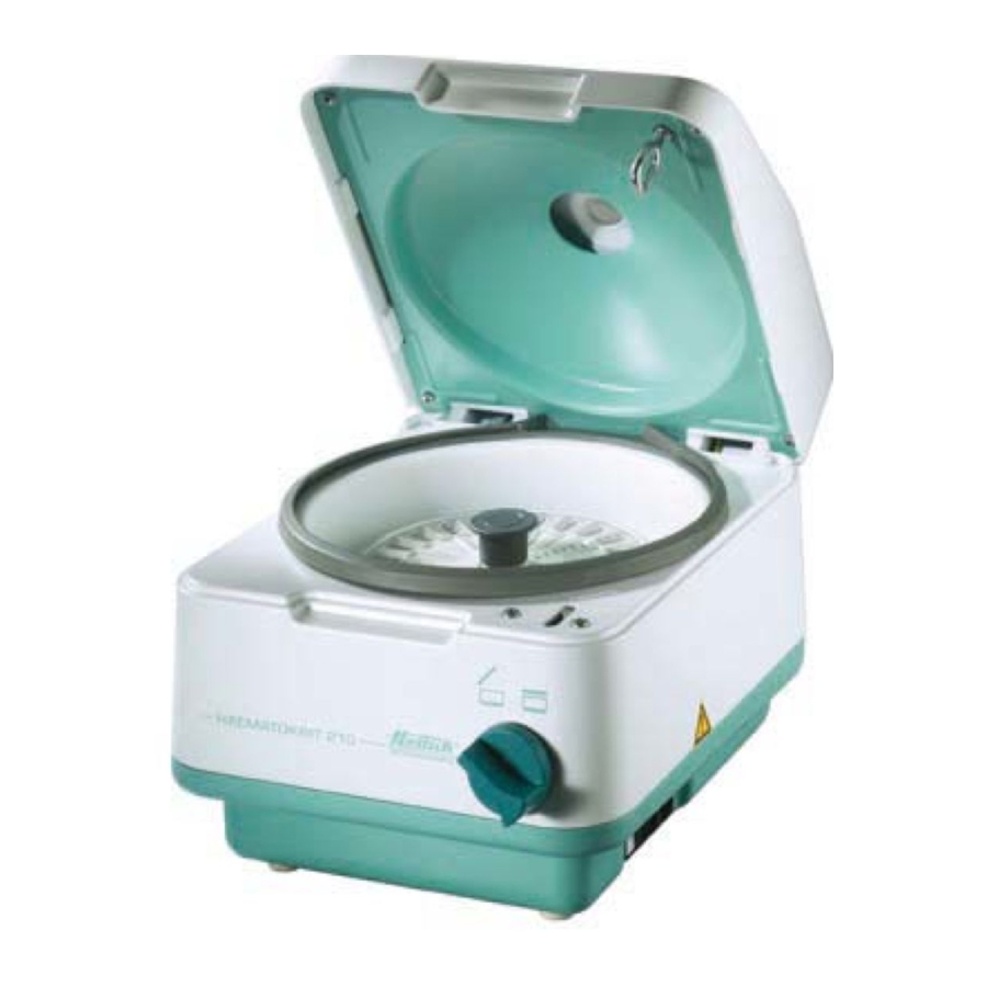
- Page 2 Fig. 1 2/62...
- Page 3 Déclaration de conformité CE Dichiarazione di conformità alle norme CEE Andreas Hettich GmbH & Co. KG • Föhrenstraße 12 • D-78532 Tuttlingen • Germany Das bezeichnete Gerät entspricht den aufgeführten EG-Richtlinien und Normen. The named device complies with specified EC guidelines and standards.
- Page 4 (07461) 705-125 info@hettichlab.com, service@hettichlab.com www.hettichlab.com © 2003 by Andreas Hettich GmbH & Co. KG All rights reserved. No part of this publication may be reproduced without the written prior permission of the copyright owner. Änderungen vorbehalten! , Modifications reserved! , Sous réserve de modifications ! , Con riserva di modifiche! AB2104DEENFRIT / 06.06...
-
Page 5: Table Of Contents
Inhaltsverzeichnis Bestimmungsgemäße Verwendung ........................7 Restrisiken ................................7 Sicherheitshinweise ..............................7 Bedeutung der Symbole ............................8 Lieferumfang................................8 Platzbedarf................................9 Netzanschluss ................................9 Inbetriebnahme...............................9 Deckel öffnen und schließen...........................9 Deckel öffnen..............................9 Deckel schließen .............................9 Bedienfeld .................................10 10.1 Drehzahlfeld...............................10 10.2 Rotationsfeld ..............................10 10.3 Zeitfeld ...............................10 10.4 Tastenfeld ..............................10 Einstellbare Parameter ............................11 Zentrifugations-Parameter vorwählen bzw. - Page 6 Störungen................................17 Netzeingangssicherungen wechseln .........................17 Reparaturannahme von Zentrifugen .........................18 Anhang / Appendix ............................61 20.1 Technische Daten / Technical specification ....................61 20.2 Rotoren und Zubehör / Rotors and accessories..................62 6/62...
-
Page 7: Bestimmungsgemäße Verwendung
Darunter fallen auch Stoffe und Stoffgemische menschlichen Ursprungs. Die Zentrifuge ist nur für diesen Verwendungszweck bestimmt. Eine andere oder darüber hinausgehende Benutzung gilt als nicht bestimmungsgemäß. Für hieraus entstehende Schäden haftet die Firma Andreas Hettich GmbH & Co. KG nicht. Zur bestimmungsgemäßen Verwendung gehört auch das Beachten aller Hinweise aus der Bedienungsanleitung und die Einhaltung der Inspektions- und Wartungsarbeiten. -
Page 8: Bedeutung Der Symbole
• Reparaturen dürfen nur von einer vom Hersteller autorisierten Person ausgeführt werden. • Es dürfen nur Originalersatzteile und zugelassenes Originalzubehör der Firma Hettich verwendet werden. • Es gelten die folgenden Sicherheitsbestimmungen: IEC 61010-1 und IEC 61010-2-020 sowie deren nationalen Abweichungen. -
Page 9: Platzbedarf
Platzbedarf • Der erforderliche Platzbedarf ist ersichtlich unter den Abmessungen im Kapitel Technische Daten. • Die Zentrifuge ist an einem geeigneten Platz standsicher aufzustellen. Bei der Aufstellung ist der geforderte Sicherheitsbereich gemäß IEC 61010-2-020, von 300 mm um die Zentrifuge herum, einzuhalten. Während eines Zentrifugationslaufes dürfen sich gemäß... -
Page 10: Bedienfeld
Bedienfeld Das Bedienfeld ist in vier Felder aufgeteilt. • Drehzahlfeld • Rotationsanzeige • Zeitfeld • Tastenfeld 10.1 Drehzahlfeld In Drehzahlfeld befindet sich die Drehzahlanzeige in welcher die vorgewählte Drehzahl oder während des Laufes die IST-Drehzahl angezeigt wird. Mit den Pfeiltasten kann die Drehzahl vorgewählt oder während des Laufes geändert werden. -
Page 11: Einstellbare Parameter
Einstellbare Parameter • Drehzahl min. Drehzahl 500 rpm • max. Drehzahl 13000 rpm • in Stufen von 100 rpm Einstellbar bis zur max. Drehzahl des eingesetzten Rotors. • Zeit min. Zeitvorwahl 1 min • max. Zeitvorwahl 99 min • in Stufen von 1 min oder ”—”... -
Page 12: Bremseinstellung
12.4 Bremseinstellung Bei dieser Zentrifuge kann die Bremswirkung auf normal oder gering eingestellt werden. Diese kann wie folgt, vor einem Lauf, eingestellt werden: Netzschalter ausschalten Impulstaste und Pfeiltaste im Drehzahlfeld gleichzeitig betätigen. Den Netzschalter einschalten und die Tasten wieder los lassen. Betätigen Sie gegebenenfalls die Pfeiltaste im Drehzahlfeld, bis die nachfolgend abgebildete Anzeige erscheint. -
Page 13: 14 Hämatokritbestimmung
Hämatokritbestimmung 14.1 Übersicht der Hämatokritkapillaren Standard-Kapillarröhrchen, Best. Nr.: 2074 Die klassische heparinisierte Hämatokritkapillare aus Glas. Seit Jahren bewährt. Mylarverstärkte Kapillarröhrchen, Best. Nr.: 1072 Die heparinisierte Glaskapillare ist mit Kunststoff ummantelt. Falls eine Kapillare bricht, werden die Glassplitter in dieser Umhüllung zurückgehalten. Dies bedeutet eine geringere Verletzungsgefahr für den Anwender. Selbstdichtende Kapillarröhrchen, Best. -
Page 14: Selbstdichtende Kapillarröhrchen (Best. Nr. 1071)
14.3.2 Selbstdichtende Kapillarröhrchen (Best. Nr. 1071) Kapillarröhrchen füllen. Blutsäule in Richtung Stopfen absinken lassen. Das Blut muss den Stopfen berühren! Kapillare mit dem Stopfenende dreimal auf den Labortisch klopfen! Das intensiviert den Kontakt mit dem Stopfenmaterial und fördert den Abdichtungsprozess. Nur so werden die Kapillaren dicht! Kapillarröhrchen, mit dem Stopfenende nach außen, in den Hämatokritrotor einlegen, den Rotordeckel aufsetzen und einrasten. -
Page 15: Pflege Und Wartung
Pflege und Wartung Vor der Reinigung den Netzstecker ziehen. Bevor ein anderes als das vom Hersteller empfohlene Reinigungs- oder Dekontaminationsverfahren angewandt wird, hat sich der Benutzer beim Hersteller zu vergewissern, dass das vorgesehene Verfahren das Gerät nicht schädigt. • Es sind Reinigungs- oder Desinfektionsmittel zu verwenden, die im pH-Bereich 5 - 8 liegen. Alkalische Reinigungsmittel mit einem pH-Wert >... -
Page 16: Rotor-Ausbau / -Einbau
16.4 Rotor-Ausbau / -Einbau Ausbau des Hämatokritrotors: Den Deckel öffnen und die Zentrifuge vom Netz trennen. Den Rotordeckel durch Drücken des Druckverschlusses abnehmen. Die Befestigungsmutter mit dem mitgelieferten Schlüssel abschrauben. Den Hämatokritrotor von der Motorwelle abziehen. Einbau des Hämatokritrotors: Den Hämatokritrotor vertikal auf die Motorwelle aufsetzen. Der Mitnehmer der Motorwelle muss sich in der Nut des Rotors befinden. -
Page 17: Störungen
Störungen Lässt sich der Fehler laut Störungstabelle nicht beheben, so ist der Hettich-Kundendienst zu benachrichtigen. Bitte den Zentrifugentyp und die Werknummer angeben. Beide Werte sind auf dem Typenschild der Zentrifuge ersichtlich. NETZ-RESET: - Netzschalter AUS, länger 10s. - Netzschalter EIN. -
Page 18: Reparaturannahme Von Zentrifugen
Reparaturannahme von Zentrifugen Wird die Zentrifuge zur Reparatur an den Hersteller zurückgesandt, so muss diese, zum Schutz von Personen, Umwelt und Material, vor dem Versand dekontaminiert und gereinigt werden. Eine Annahme von kontaminierten Zentrifugen behalten wir uns vor. Anfallende Kosten für Reinigungs- und Desinfektionsmaßnahmen werden dem Kunden in Rechnung gestellt. Wir bitten dafür um Ihr Verständnis. - Page 19 Contents Use according to specification ..........................21 Residual risks ...............................21 Notes on safety..............................21 Symbol meanings ..............................22 Delivery checklist ..............................22 Space requirement ...............................23 Connection to the mains ............................23 Commissioning ..............................23 Opening and closing the lid...........................23 Opening the lid ..............................23 Closing the lid ..............................23 Control panel ..............................24 10.1 Speed area ..............................24...
- Page 20 Faults ................................31 Change mains input fuse...........................32 Acceptance of the centrifuges for repair......................32 Anhang / Appendix ............................61 20.1 Technische Daten / Technical specification ....................61 20.2 Rotoren und Zubehör / Rotors and accessories..................62 20/62...
-
Page 21: Use According To Specification
A different use or application over and above this is deemed not in accordance with the specifications. The company Andreas Hettich GmbH & Co. KG undertakes no liability for damages resulting therefrom. Belonging to the application according to specification is also the observance of all references contained in the Instruction Manual and compliance with the inspection and maintenance works. -
Page 22: Symbol Meanings
• Repairs must only be carried out by personnel authorised to do so by the manufacturer. • Only original spare parts and original accessories licensed by the Hettich company are allowed to be utilised. • The following safety regulations apply: IEC 61010-1 and IEC 61010-2-020 as well as their national deviations.. -
Page 23: Space Requirement
Space requirement • The necessary space requirement can be found under Dimensions in the Technical data chapter. • The centrifuge must be set up in a suitable place, so that it is stable. During set-up, the required safety margin of 300 mm around the centrifuge is to be kept according to IEC 61010-2-020. -
Page 24: Control Panel
Control panel The control panel is divided into four areas. • Speed • Rotation display • Time • Keys 10.1 Speed area The speed area contains the speed display which indicates the preselected speed or the ACTUAL speed during operation. The speed can be preselected or changed during operation with the arrow keys. -
Page 25: Adjustable Parameters
Adjustable parameters • Speed min. speed 500 rpm • max. speed 13000 rpm • in steps of 100 rpm Adjustable up to max. speed of the rotor used. • Time min. preset time 1 min • max. preset time 99 min •... -
Page 26: Brake Adjustment
12.4 Brake adjustment With this centrifuge, the braking effect can be set to normal or low. This can be set before a run, as follows: Switch off the mains switch Simultaneously press the pulse key and the arrow key in the speed area and switch on the mains switch. Release the keys again. -
Page 27: Haematocrit Measurement
Haematocrit measurement 14.1 Haematocrit capillaries - Overview Standard capillary tubes, Order No.: 2074 The classical heparinized haematocrit capillary tube made of glass. Tried and tested for years. Mylar-reinforced capillary tubes, Order No.: 1072 The heparinized glass capillary is coated with plastic. Should such a capillary break the glass splinters are retained in this coating. -
Page 28: Self-Sealing Capillary Tubes (Order No. 1071)
14.3.2 Self-sealing capillary tubes (Order No. 1071) Fill the capillary tube. Let the column of blood settle in the direction of the seal. The blood must touch the seal! Tap the seal end of the capillary three times on the laboratory table! This serves to intensify the contact with the seal material and to enhance the sealing process. -
Page 29: Maintenance And Servicing
Maintenance and servicing Pull the mains plug before cleaning. Before any other cleaning or decontamination process other than that recommended by the manufacturer is applied, the user has to check with the manufacturer that the planned process does not damage the device. •... -
Page 30: Rotor Removal / Installation
16.4 Rotor removal / installation Removal of haematocrit rotor: Open the lid and disconnect the centrifuge from the power supply. Remove the rotor lid by pressing the press lock. Unscrew the fixing nut with the supplied spanner. Pull the haematocrit rotor off the motor shaft. Installation of the haematocrit rotor: Insert the haematocrit rotor vertically onto the motor shaft. -
Page 31: Faults
Faults If the fault cannot be rectified according to the faults table, Hettich customer services must be informed. Please state the type of centrifuge and the factory serial number. Both values are visible on the centrifuge type plate. MAINS RESET: - Mains switch OFF for longer than 10 secs. -
Page 32: Change Mains Input Fuse
• Reinsert the fuse holder until the snap-fit clicks shut. • Reconnect the centrifuge to the mains supply. Model Type Fuse Order no. HAEMATOKRIT 210 2104 T 3,15 AH/250V E997 HAEMATOKRIT 210 2104-01 T 5 AH/250V E914 Acceptance of the centrifuges for repair If the centrifuge is returned to the manufacturer for repair, it must be decontaminated and cleaned to protect persons, environment and material. - Page 33 Table des matières Usage conforme ..............................35 Risques résiduels ..............................35 Consignes de sécurité ............................35 Signification des symboles............................36 Composition de la livraison ...........................36 Encombrement ..............................37 Branchement au secteur............................37 Mise en service..............................37 Ouvrir et fermer le couvercle..........................37 Ouvrir le couvercle............................37 Fermer le couvercle ............................37 Tableau de commande............................38 10.1 Partie vitesse de rotation..........................38...
- Page 34 Défauts................................45 Changer les fusibles d'entrée de secteur ......................46 Réparation des centrifugeuses..........................46 Anhang / Appendix ............................61 20.1 Technische Daten / Technical specification ....................61 20.2 Rotoren und Zubehör / Rotors and accessories..................62 34/62...
-
Page 35: Usage Conforme
La centrifugeuse est uniquement destinée à cette utilisation. Tout usage autre ou dépassant ce contexte est considéré comme non-conforme. La société Firma Andreas Hettich GmbH & Co. KG décline toute responsabilités pour les dégâts causés par un usage non-conforme. -
Page 36: Signification Des Symboles
Les réparations ne peuvent être effectuées que par une personne autorisée à cet effet par le fabricant. • Utiliser uniquement les pièces de rechange originales et les accessoires d'origine homologués par les Etablissements Hettich. • Les dispositions de sécurité suivantes font foi : IEC 61010-1 et IEC 61010-2-020 ainsi que les dérogations nationales. -
Page 37: Encombrement
Encombrement • L’encombrement est à reprendre; sous dimensions au chapitre; Caractéristiques techniques. • La centrifugeuse est à installer à un endroit approprié de manière stable. Lors de la mise en place, il faut respecter la zone de sécurité exigée de 300mm autour de la centrifugeuse selon IEC 61010-2-020. Durant un processus de centrifugation, aucune personne, matière dangereuse et aucun objet ne doivent se trouver dans une zone de sécurité... -
Page 38: Tableau De Commande
Tableau de commande Le tableau de commande est divisé en quatre parties. • Partie vitesse de rotation • Partie rotation • Partie durée • Partie des touches 10.1 Partie vitesse de rotation Dans la partie vitesse de rotation se trouve l’affichage de la vitesse de rotation où la vitesse rotation sélectionnée ou la vitesse de rotation REELLE pendant l’opération est affichée. -
Page 39: Paramètres Ajustables
Paramètres ajustables • Vitesse de rotation vitesse de rotation min. 500 rpm • vitesse de rotation max. 13000 rpm • ajustage en intervalles de 100 rpm jusqu’à la vitesse de rotation max. du rotor mis en service. • Durée présélection min. de la durée 1 minute •... -
Page 40: Ajustage Du Freinage
12.4 Ajustage du freinage Sur cette centrifugeuse, l’efficacité du freinage peut être ajustée de normale à faible. Celle-ci peut être ajustée avant une opération comme suit : Couper le courant avec l’interrupteur du secteur Actionner simultanément, la touche impulsion et la touche fléchée dans la partie vitesse de rotation, remettre le courant avec l’interrupteur du secteur et relâcher à... -
Page 41: 14 Détermination De L'hématocrite
Détermination de l'hématocrite 14.1 Vue d'ensemble des capillaires pour hématocrite Tubes capillaires standards, n° de commande : 2074 Les capillaires pour hématocrite héparinisés en verre, qui ont fait leurs preuves depuis des années. Tubes capillaires en Mylar renforcé, n° de commande : 1072 Le capillaire héparinisé... -
Page 42: Tubes Capillaires Auto-Étanches (N° De Commande 1071)
14.3.2 Tubes capillaires auto-étanches (n° de commande 1071) Remplir le tubes capillaire. Laisser descendre la colonne de sang en direction du bouchon. Le sang doit toucher le bouchon ! Frapper trois fois avec l'extrémité obturée du capillaire sur le plan de travail ! Cela intensifie le contact avec le matériel d'obturation et favorise le processus d'obturation. -
Page 43: Entretien Et Maintenance
Entretien et maintenance Retirer la prise de secteur avant de nettoyer. Avant d'utiliser une procédure de nettoyage ou de décontamination autre que celle recommandée par le fabricant, l'utilisateur vérifiera auprès du fabricant que la procédure prévue n'endommage pas l'appareil. • Utiliser des agents de nettoyage et de désinfection de pH entre 5 et 8. -
Page 44: Démontage / Remontage Du Disque De Centrifugation
16.4 Démontage / remontage du disque de centrifugation Démontage du disque de centrifugation : Ouvrir le couvercle et débrancher la centrifugeuse du réseau. Déposer le couvercle en appuyant sur l'obturateur à pression. Dévisser l’écrou de fixation avec la clé livrée dans la fourniture. Retirer le disque de centrifugation de l'arbre du moteur. -
Page 45: 17 Défauts
Défauts Si l'erreur ne peut pas être corrigée selon le tableau des dérangements, faire appel au service consommateurs de Hettich. Vous aurez l'obligeance de mentionner le modèle de centrifugeuse et le numéro d'usine. Les deux sont marqués sur la plaque signalétique de la centrifugeuse. -
Page 46: Changer Les Fusibles D'entrée De Secteur
Remettre en place le porte-fusible et pousser jusqu'à encastrement de la fermeture rapide. • Rétablir le raccord de la centrifugeuse au secteur. Modèle Type Fusible N° de commande HAEMATOKRIT 210 2104 T 3,15 AH/250V E997 HAEMATOKRIT 210 2104-01 T 5 AH/250V E914 Réparation des centrifugeuses Dans le cas où... - Page 47 Indice Uso previsto................................49 Rischi residui ................................49 Indicazioni inerenti la sicurezza ..........................49 Significato dei simboli ............................50 Contenuto della fornitura............................50 Ingombro................................51 Collegamento alla rete ............................51 Messa in funzione ..............................51 Apertura e chiusura del coperchio ........................51 Apertura del coperchio...........................51 Chiusura del coperchio ..........................51 Pannello di comando............................52 10.1 Numero di giri.............................52...
- Page 48 16.4 Montaggio / smontaggio rotore ........................58 Guasti................................59 Sostituzione fusibili entrata rete ........................59 Accettazione di centrifughe da riparare ......................60 Anhang / Appendix ............................61 20.1 Technische Daten / Technical specification ....................61 20.2 Rotoren und Zubehör / Rotors and accessories..................62 48/62...
-
Page 49: Uso Previsto
1,2 kg/dm³. Sono comprese anche sostanze e miscele di origine umana. La centrifuga deve essere utilizzata unicamente per questo scopo. Qualsiasi altro tipo di utilizzo è improprio. La ditta Andreas Hettich GmbH & Co. KG non risponde dei danni che ne conseguono. -
Page 50: Significato Dei Simboli
Gli interventi di riparazione devono essere effettuati esclusivamente da una persona autorizzata dal costruttore. • Devono essere impiegati solo ed esclusivamente pezzi di ricambio originali ed accessori autorizzati della ditta Hettich. • Sono di validità le seguenti norme di sicurezza: IEC 61010-1 e IEC 61010-2-020 come anche le loro nazionali varianti. -
Page 51: Ingombro
Ingombro • L‘ingombro necessario è evidente in base alle misure nel capitolo Dati tecnici. • La centrifuga deve essere installata in modo stabile in un posto idoneo. Per l’installazione deve essere rispettata la zona di sicurezza di 300 mm attorno alla centrifuga, richiesta in conformità alle norme IEC 61010-2-020. Durante un’operazione di centrifugazione, in una zona di sicurezza di 300 mm attorno alla centrifuga non deve sostare alcuna persona, materiali pericolosi ed oggetti, in conformità... -
Page 52: Pannello Di Comando
Pannello di comando Il pannello di comando è suddiviso in quattro settori: • Numero di giri • Indicatore di rotazione • Tempo • Tasti 10.1 Numero di giri Nel pannello del numero di giri si trova l‘indicatore del numero di giri, in cui viene indicato il numero di giri preselezionato o il numero di giri effettivo durante il funzionamento. -
Page 53: Parametri Regolabili
Parametri regolabili • Numero di giri numero di giri min. 500 rpm • numero di giri max.13000 rpm • con progressione di 100 rpm Regolabile fino al numero massimo di giri del rotore installato. • Tempo preselezione di tempo min. 1 min. •... -
Page 54: Regolazione Della Frenatura
12.4 Regolazione della frenatura In questa centrifuga l‘effetto frenante può essere regolato su normale o ridotto. Questo può essere regolato, prima del funzionamento, come segue,: Disinserire l‘interruttore generale Azionare contemporaneamente il tasto Impuls e il tasto a freccia nel pannello del numero di giri e accendendo l‘interruttore generale e rilasciare nuovamente i tasti. -
Page 55: Accelerazione Centrifuga Relativa (Rcf)
Accelerazione centrifuga relativa (RCF) L’accelerazione centrifuga relativa (RCF) è indicata come un multiplo dell’accelerazione terrestre (g). È un valore numerico privo di unità e funge per paragonare le prestazioni di separazione de sedimentazione. Il calcolo viene eseguito in base alla formula: ⎛... -
Page 56: Chiusura E Centrifugazione Delle Provette Capillari D'ematocrito
14.3 Chiusura e centrifugazione delle provette capillari d’ematocrito 14.3.1 Provette capillari standard, Cod. d’ordinazione: 2074 e provette capillari rinforzate di mylar, Cod. d’ordinazione: 1072 Durante il riempimento prestare attenzione che l’estremità della provetta capillare sita di fronte all’apertura di riempimento rimanga asciutta. Stuccare l’estremità... -
Page 57: Sblocco Di Emergenza
Sblocco di emergenza In caso di una caduta di tensione non è possibile aprire il coperchio. Deve essere effettuata manualmente uno sblocco di emergenza. Per lo sblocco di emergenza, disconnettere la centrifuga dalla rete elettrica. Aprire il coperchio solo con l’arresto del rotore. Vedere illustrazione alla pagina 2. -
Page 58: Montaggio / Smontaggio Rotore
16.4 Montaggio / smontaggio rotore Smontaggio del rotore ematocrito: Aprire il coperchio e separare la centrifuga dalla rete. Togliere il coperchio del rotore premendo sulla chiusura a pressione. Svitare il dado di fissaggio con la chiave in dotazione. Asportare il rotore ematocrito dall’albero motore. Montaggio del rotore ematocrito: Applicare il rotore ematocrito verticalmente sull’albero motore. -
Page 59: Guasti
• Inserire di nuovo il portafusibili fino a far scattare la chiusura. • Collegare di nuovo alla rete la centrifuga. Modello Tipo Fusibile N° ord. HAEMATOKRIT 210 2104 T 3,15 AH/250V E997 HAEMATOKRIT 210 2104-01 T 5 AH/250V E914 59/62... -
Page 60: Accettazione Di Centrifughe Da Riparare
Accettazione di centrifughe da riparare Nel caso in cui la centrifuga debba essere rispedita al produttore per una eventuale riparazione, prima della spedizione deve essere decontaminata e pulita a fondo a salvaguardia delle persone, dell’ambiente e del materiale. Ci riserviamo di accettare centrifughe contaminate. Eventuali costi di pulizia e disinfezione verranno fatturati al cliente. -
Page 61: Anhang / Appendix
20.1 Technische Daten / Technical specification Hettich Zentrifugen Hersteller / Manufacturer D-78532 Tuttlingen Typenbezeichnung / Model HAEMATOKRIT 210 Verkaufs-Nr. / Product no. 2104 2104-01 Netzspannung / Mains voltage ( ± 10%) 208 - 240 V 1 ∼ 100 - 127 V 1 ∼... -
Page 62: Rotoren Und Zubehör / Rotors And Accessories
20.2 Rotoren und Zubehör / Rotors and accessories 2056 Hämatokritrotor (QBC) 20-fach (mit Deckel) Haematocrite rotor (QBC) 20-times Reduzierung / adapter (with lid) ---- Kapillare/ Capillaries Kapillare QBC / Capillaries Kapazität / capacity Maße / dimensions ∅ x L Anzahl p. Gestell/number p. frame Anzahl p.
Need help?
Do you have a question about the HAEMATOKRIT 210 and is the answer not in the manual?
Questions and answers