Table of Contents

Related Manuals for Hettich ROTOFIX 32


Summary of Contents for Hettich ROTOFIX 32
- Page 1 Repair instructions ROTOFIX 32 02.06 AR087GB Andreas Hettich GmbH & Co. KG • Föhrenstraße 12 • D-78532 Tuttlingen • Germany Phone: (07461) 705-0 • Fax: (07461) 705-125 • Internet: www.hettichlab.com • e-mail: info@hettichlab.com, service@hettichlab.com...
- Page 2 No part of this publication may be reproduced without the written prior permission of the copyright owner. © 1999 by Andreas Hettich GmbH & Co. KG,D-78532 Tuttlingen / Germany. Technical alterations reserved! 2/34...
-
Page 3: Table Of Contents
Contents Introduction ......................5 Description of the centrifuge..................6 Control panel A3 ....................7 Power board A1 ....................7 Motor M1......................8 Speed sensor B3....................8 Brake resistor (R1) and overtemperature fuse (F3)........... 8 Lid lock Y1 ......................8 Imbalance switch S 2 ..................8 Troubleshooting procedures.................. - Page 4 Brake resistor R1 and overtemperature fuse F3........29 9.2.4 Lid lock Y1 ....................29 9.2.5 Imbalance switch ..................30 9.2.6 Intermediate voltage on power board A1 ..........30 Technical data ....................31 Skeleton construction of ROTOFIX 32 ............... 32 Index ........................33 4/34...
-
Page 5: Introduction
• This repair instruction is only intended for specialized staff authorized by HETTICH. Interventions and modifications at centrifuges, which have been conducted by persons not authorized by HETTICH, are at their own risk and entail the loss off all guarantee and liability claims. In such an event any guarantee claim or liability claim against the HETTICH expire. -
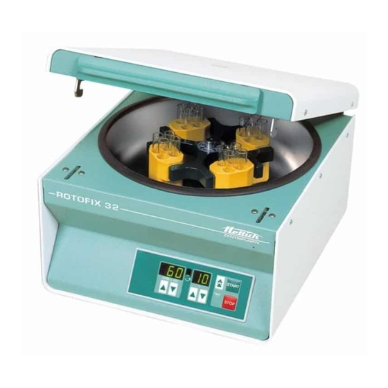
Page 6: Description Of The Centrifuge
Description of the centrifuge The ROTOFIX 32 is a microprocessor-controlled centrifuge which is comprised of the following electrical components: • Control panel • Power board • Motor • Speed sensor (Tacho) • Brake resistor with overtemperature fuse • Lid lock system •... -
Page 7: Control Panel A3
Control panel A3 The control panel have only restricted control tasks, it disposes of the following characteristics: • Input panel for operation parameters • Indication elements • Transmission of the signals to the power board via the interface. • Storing the machine version and the brake setting. By means of the machine version the power board is informed which kind of centrifuge has to be controlled. -
Page 8: Motor M1
Motor M1 • The motor is a three- phase asynchronous motor with two pairs of poles. • The motor is protected against overheating by an overtemperature switch. • The power board evaluates the overtemperature switch. • The motor is controlled by the power board with a three-phase current with variable frequency and voltage. -
Page 9: Troubleshooting Procedures
Troubleshooting procedures • Fuses in installation in which centrifuge is installed are intact. • Mains input fuses of centrifuge are intact. • Supply voltage present at (see circuit diagram): − Connecting cable − Appliance plug − Mains switch − Power board A1, plug S402L and S402N •... -
Page 10: Error Messages
Error messages The error message will be indicated in the speed display of the front panel. e.g. : START R PM x 100 STOP Fehlermeldung / Error indication MAINS RESET • Switch off the mains switch. • Wait at least for 10 seconds and then switch on the mains switch again. Brief description Display. -
Page 11: Description And Elimination Of Errors
Description and elimination of errors – 1 – Tacho error Error Tacho pulses break down during the run. Error Drive switch off and brakes with the adjusted brake level. consequence • Speed sensor (tacho) defective Error cause • Power board (A1) defective •... - Page 12 – 4 – Communication Error Communication error between control board and power board Error Drive switch off . No brake effective consequence Error cause • Loose contact in flat ribbon cable • Control board (A3) defective • Power board (A1) defective Error code reset MAINS RESET after stand still.
- Page 13 – 8 – Undervoltage Error Mains voltage less than 20% as nominal voltage. Error Drive switches off. No brake effective consequence Error cause • Mains voltage too less • Power board (A1) defective Measurement Check the mains voltage Measure intermediate voltage, see chapter 9.2.6 Error code reset Perform a MAINS RESET after standstill.
- Page 14 – c – Controller-Watchdog Error Watchdog in power board Discrepancy in program procedure Error Drive switches off. No brake effective consequence • Power board (A1) defective Error cause Error code reset Perform a MAINS RESET after standstill. – d – Lid lock error Error Lid lock is open during centrifugation.
- Page 15 - F - Rotor code No rotor code after start-up. Error Drive switches off after 15 sec. No brake effective Error consequence • Start-up took place without the rotor. Error cause • Motor is defective. • Power board (A1) defective Speed sensor (speedometer) defective, or loose contact on plug.
-
Page 16: Defects Without Error Indications
Maschinenversion / Machine version Proceed as the following: 1. Adjust the correct machine version by using the arrow keys in the time area. ROTOFIX 32 = 4 MIKRO 20 EBA 20 2. Press the key in order to store STOP the set machine version. - Page 17 The lid can not be opened The lid can not be opened Error The rotation display indicates "Lid closed" and the lid is closed. Error cause • Solenoid on lid lock is defective • Loosen contact on plug S404 / Pin 1 and 3 •...
-
Page 18: Settings And Enquiries
(ROTOFIX 32). If another machine version than 4 is set in the control panel, the set machine version will appear in the display after switching on the centrifuge ROTOFIX 32. The machine version 4 must be set as follows: 1. Adjust the machine version 4 by... -
Page 19: Enquiry The Programme Versions
Enquiry the programme versions 1. Switch off the mains switch. 2. Simultaneously press the pulse key and the arrow key in the speed area. Switch on the mains switch and release the keys again. 3. Press the key in the speed area so often until the programme version of the control panel (e.g. -
Page 20: Lid Lock Control
Lid lock control With the centrifuge ROTOFIX 32 the solenoid of the lid lock is energized automatically when the rotor is at standstill. After the lid is opened the solenoid will drop out again. With this kind of lid lock control, the jumper for the lid lock control on the power board (see below) may not be plugged. -
Page 21: Functional Check After A Repair
Functional check after a repair After a repair a functional check of the unit must be carried out. For functional check a test run with the loaded rotor must be performed. During the test run the followings must be checked: •... -
Page 22: Speedometer-Code-Position Of The Rotor
Speedometer-code-position of the rotor Example: tachometer code no. 2 Rotor viewed from underneath START North Pole START-STOP combination Information tachometer code determines: 1. maximum speed of rotor 2. run up and braking ramps 3. control response of electronics Rotor 1001 0001 1011 Rotor code Start / Stop Combination Tacho code-Nr. -
Page 23: Assembling And Disassembling Components
Assembling and disassembling components Component Abbreviation Plug Connected to Description in chapter Speed sensor S502 Motor S401 Rubber-metal bearing Power board Control panel Flat ribbon cable A1 to A3 Lid lock S404 8.11 Brake resistor S405 Overtemperature fuse S405 Mains switch Appliance plug Imbalance switch S503... -
Page 24: Speed Sensor (Tacho) B3
Speed sensor (Tacho) B3 • Remove the two fastening screw of the speed sensor. • remove the speed sensor from the to of the motor • Unplug the plug S502 from the power board • remove the cable clip which fix the cable of the speed sensor on the motor. •... -
Page 25: Overtemperature Fuse F3
Overtemperature fuse F3 • Remove the two cables from the overtemperature fuse. • Unscrew the fastening screws. • Exchange the overtemperature fuse. Flat ribbon cable • Unplug the flat ribbon cable from the power board. • Disassemble the control board from the housing(see section 8.4). •... -
Page 26: Circuit Diagrams
Circuit diagrams Used cable colours and their abbreviations: Abbreviation Colour black brown blue GN/YE green-yellow grey white yellow 26/34... -
Page 27: Circuit Diagram And Plug Assignment
Circuit diagram and plug assignment S402L S402N Motor Übertemp. -schalter Overtemp. switch S402P UR US UT S401 Bremswiderstand Übertemp.-sicherung S404 Brake resistor Overtemp. fuse Deckel- verriegelung Unwuchtschalter Tacho S405 Lid lock Imbalance switch Speedometer S503 S502 2 3 4 Leistungsteil S501 Power board Jumper für Verschlußansteuerung... -
Page 28: Signals And Test Results
Signals and test results 9.2.1 Speed sensor (Tacho) B3 Power supply: Plug S502, measure between Pin 2 (GND)and 3: Tacho signal: Plug S502 measure between Pin 2 (GND) and 4: 6 pulse per round 9.2.2 Motor Motor coil Remove plug S401 and measure between two lines: 230 V version: ≈... -
Page 29: Brake Resistor R1 And Overtemperature Fuse F3
9.2.3 Brake resistor R1 and overtemperature fuse F3 S405 Brake resistor R1 Remove plug S405 and measure between pin 1 and 2 : ≈ 330 Ω 230 V Version: Ω Ω ≈ 82 Ω 120 V Version: Overtemperature fuse F3 Remove plug S405 and measure directly at both flat connections of the overtempera- ture fuse:... -
Page 30: Imbalance Switch
9.2.5 Imbalance switch Remove plug S503 and measure between pin 1 and pin 4 : ∞ Ω Switch pressed : Switch inoperative: ≈ 0 Ω 9.2.6 Intermediate voltage on power board A1 The intermediate voltage has to be measured during the run ( run-up, run and run-down). -
Page 31: Technical Data
10 Technical specification Hettich Zentrifugen Hersteller / Manufacturer D-78532 Tuttlingen Typenbezeichnung / Model ROTOFIX 32 1205, 1205-01 Verkaufs-Nr. / Product no. 1205-14 1205-15 208 – 240 V 1~ 100 – 127 V 1 ~ Netzspannung / Mains voltage (± 10%) Netzfrequenz / Mains frequency 50 –... -
Page 32: Skeleton Construction Of Rotofix 32
11 Skeleton construction of ROTOFIX 32 Viewing window Lid complete Motor hood Speed sensor (Tacho) Chamber Carrier pin Motor Anti-twist device Rubber-metal bearing 10 Hinge 11 Fuse insert 12 Appliance plug 13 Rubber foot 14 Power board 15 Electronic control... -
Page 33: 12 Index
12 Index – 1 – Tacho error......................11 – 2 – System reset ......................11 – 3 – Imbalance......................11 – 4 – Communication ....................12 – 5 – Overload....................... 12 – 6 – Overvoltage ......................12 – 8 – Undervoltage ......................13 –... - Page 34 Machine version......................18 Machine-Version-Error ....................16 Mains fuse........................25 mains switch ......................... 25 Motor........................8, 24, 28 Motor coil ........................28 No display ........................17 No speed indication ...................... 16 Overtemperature fuse ..................8, 25, 29 Overtemperature switch ....................28 Permissible imbalance ....................
Need help?
Do you have a question about the ROTOFIX 32 and is the answer not in the manual?
Questions and answers
We are looking to replace 12 cyto clips that came with our Hettich Rotofix zentrifugen 32A. Could we get a part number and where we can order these? Centrifuge info: SN 0006860-04 Ref 1206-01