Hettich EBA 21 Repair Instructions
Hide thumbs
Also See for EBA 21:
- Operating instructions manual (58 pages) ,
- Operating instructions manual (80 pages)
Table of Contents
Advertisement
Advertisement
Table of Contents

Related Manuals for Hettich EBA 21


Summary of Contents for Hettich EBA 21
- Page 1 Repair instructions EBA 21 03.06 Andreas Hettich GmbH & Co. KG AR1004EN...
- Page 2 (07461) 705-0 (07461) 705-125 info@hettichlab.com, service@hettichlab.com www.hettichlab.com © 2003 by Andreas Hettich GmbH & Co. KG All rights reserved. No part of this publication may be reproduced without the written prior permission of the copyright owner. Modifications reserved! AR1004EN / 03.06...
-
Page 3: Table Of Contents
Contents Introduction ......................5 Symbol meanings..................... 5 Description of the centrifuge..................6 Control panel (A4) ..................... 6 Supply board (A1) ..................... 6 Frequency converter (A2) ................. 7 Special features ....................8 Brake resistor (R1) .................... 8 Motor / tacho system..................8 Lid lock...................... - Page 4 Mounting and removing components ..............29 10.1 Removing the centrifuge chamber ..............29 Short the mains choke coil (L1) ................30 Technical documents ..................31 12.1 Tachometer code configuration of the rotors ..........31 12.2 Circuit diagrams....................32 12.2.1 Abbreviations of the cable colours............32 12.2.2 Mains supply with supply board (A1) 230 V..........
-
Page 5: Introduction
Interventions and modifications at centrifuges, which have been conducted by persons not authorized by the HETTICH company, are at their own risk and entail the loss off all guarantee and liability claims. In such an event any guarantee claim or liability claim against the HETTICH company expire. -
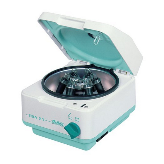
Page 6: Description Of The Centrifuge
Description of the centrifuge These microprocessor controlled centrifuges mainly consist of the following electrical components: • Control panel, microprocessor controlled • Supply board • Frequency converter with braking chopper (motor control), microprocessor controlled • Motor with speed sensor (speedometer) and imbalance switch •... -
Page 7: Frequency Converter (A2)
• The 5 Volt interface with three wires is transferred to a RS 485 interface with two wires. Interface for the frequency converter: RS 485 interface via two wires • Transmitting the main enable signal (= Hardware STOP) control panel ⇒ frequency converter •... -
Page 8: Special Features
Special features • Multiprocessor concept: If a processor stops working, the other processor still continue monitoring its area. If there is a control panel failure, the frequency converter automatically switches off the drive if no inquiries are made via the interface for longer than 60 seconds. •... -
Page 9: Imbalance Switch
Imbalance switch • A switch (break contact) detects imbalance. • Imbalance is detected only in running mode (starting, centrifuging and braking). • If imbalance is detected, the drive is brought to a standstill. Safety devices Mains input ⇒ Mains fuses ⇒... -
Page 10: Error Messages
Error messages MAINS RESET • Switch off the mains switch. • Wait for 10 seconds and then switch on the mains switch again. Brief description Error designation Brief description Page TACHO-ERROR Speedometer pulses break down during rotation TACHO-ERROR No speedometer pulses after start command IMBALANCE (03)* Imbalance on motor axle CONTROL-ERROR... - Page 11 Error designation Brief description Page SER I/O-ERROR No connection between control panel and serial interface SER I/O-ERROR No connection between frequency converter and serial interface SER I/O-ERROR Data incorrectly transmitted from the componentry SER I/O-ERROR Data incorrectly transmitted between control panel and frequency converter SER I/O-ERROR No acknowledgement (NAK) from frequency...
-
Page 12: Description And Elimination Of Errors
Description and elimination of errors TACHO - ERROR 01 Error During centrifugation the speedometer pulses are interrupted. Error The rotor slows down until it stops. consequence After the rotor stops, there is a DC braking for 30 sec. An MAINS RESET during slowing-down causes a DC braking for 3 min. - Page 13 IMBALANCE Error Imbalance on motor axle. Error The centrifuge slows down until the “open the lid” release consequence occurs. • Weight difference in rotor components. Cause of error / measurements • Supporting lugs not lubricated. • False IMBALANCE MODE is set (see chapter "Imbalance Mode").
- Page 14 N > MAX 05 Error Excess speed. The speed recognised by the speed sensor (speedometer) is 250 RPM greater than the n-max speed of the rotor. Error The centrifuge slows down until the ”open the lid” release consequence occurs. Cause of error •...
- Page 15 VERSION - ERROR 12 Error Differences in the initialization from control panel (EPROM) or frequency converter. Error No further user operation is possible. consequence Cause of error • An incorrect EPROM has been plugged into control panel. • Centrifuge is not initialised. Carry out an initialization, see chapter "Initialization".
- Page 16 N > ROTOR-MAX Error Error in the entered program Error Further operation is not possible. consequence Cause of error SET speed or SET RCF is higher than the permissible rotor speed or permissible rotor RCF. Error code reset Carry out a MAINS RESET or open the lid. Reduce the speed or RCF in the entered program to the permissible rotor speed or permissible rotor RCF.
- Page 17 SER I/O - ERROR 34 Error Control panel is not receiving correct data from frequency converter. Error The centrifuge slows down until the ”open the lid” release consequence occurs. • Flat ribbon cable to frequency converter is defective. Cause of error •...
- Page 18 General Notice for FU / CCI - ERROR 61 to FU / CCI - ERROR 69 • Frequency converter switches independently. Error consequence • The rotor freewheels, coasting. • No further user operation is possible. Error code reset • Mains switch is OFF. Switch mains switch to ON after 1 min.
- Page 19 FU / CCI - ERROR 64 Error Voltage in intermediate circuit: >410 V DC at 230 V >205 V DC at 115 V This error normally only occurs when the drive is being braked. Cause of error • Brake resistor is defective. •...
- Page 20 FU / CCI - ERROR 84 Error Frequency converter recognises excess speed. During rotation the speedometer pulses (6 per revolution) are controlled by the frequency converter. This control is independ- ent from the control panel. The frequency converter switches the centrifuge off, when the maximum speed of the rotor is exceeded more than 500 rpm.
-
Page 21: Settings And Interrogations
Settings and interrogations Initialization Initialization means adjusting the frequency converter to the centrifuge. Observe the following instructions when replacing the frequency converter: • The frequency converter must be adjusted to the centrifuge. • The suitable EPROM for the machine version must be plugged in the control panel. -
Page 22: Initializing The Centrifuge
6.1.2 Initializing the centrifuge PROG >RCF< t / min:s IMPULS START STOP PROG An initialization must be carried out: • after replacing the frequency converter. The frequency converter must be adjusted to the centrifuge. 1. Prepare the centrifuge for the initialization (see chapter "Prerequisites for the initialization"). -
Page 23: Imbalance Mode
Imbalance Mode From programme version 3.00 it is necessary to set the imbalance mode during the initialization. Depending on the supply board version IMBALANCE MODE 1 or IMBALANCE MODE 2 must be selected. If the incorrect imbalance mode is selected, the display shows error "IMBALANCE"... -
Page 24: Working Hours
Working hours You can check and change the working hours only if the rotor is at standstill. • Keep the key pressed for 8 seconds. After 8 seconds, SOUND / BELL XXX will be displayed. • Press the key again. The working hours (CONTROL: ) of the centrifuge will be displayed. -
Page 25: Setting The Display Contrast
Setting the display contrast The contrast of the display has been preset by the manufacturer. However, you can readjust it. Use a screwdriver with insulated shank to make this setting as there is a risk of short circuit on the printed circuit board. Use the screwdriver to set the contrast on the trimming potentiometer on the rear side of the control panel (see figure). -
Page 26: Change Mains Input Fuse
See the following table. • Reinsert the fuse holder until the snap-fit clicks shut. • Reconnect the centrifuge to the mains supply. Model Type Fuse Order no. EBA 21 1004, 1004-30 T 3,15 AH/250V E997 EBA 21 1004-01, 1004-31 T 6,3 AH/250V 2266 Functional check after a repair After a repair a functional check of the unit must be carried out. -
Page 27: General Arrangement Of The Components
General arrangement of the components Item Components Abbrevia- plug Connection Circuit diagram tion at boards in chapter Rubber foot Turning handle Sight glass and gluing ring Control panel 12.2.7, 12.2.8 Frictional rubber Leg spring Appliance plug combination 12.2.2, 12.2.3 element (without fuse holder) Fuse holder Fuse F1, F2... - Page 28 20.1 20.2 28/42...
-
Page 29: 10 Mounting And Removing Components
10 Mounting and removing components Wait at least 2 minutes after disconnecting the centrifuge from the mains, until the intermediate circuit capacitors of the frequency converter are unloaded. All components can be mounted and removed through the centrifuge chamber. For that purpose the centrifuge chamber must be taken out, see chapter "Removing the centrifuge chamber". -
Page 30: Short The Mains Choke Coil (L1)
11 Short the mains choke coil (L1) In countries, in which the European standard EN 61000-3-2 applies it is not allowed to short the mains choke coil. The mains choke coil reduces the mains input current below the limit values stated in the above mentioned European standard. -
Page 31: 12 Technical Documents
12 Technical documents 12.1 Tachometer code configuration of the rotors Example: tachometer code no. 1 Rotor viewed from underneath START North Pole START-STOP combination Information tachometer code determines: 1. maximum speed of rotor 2. run up and braking ramps 3. control response of electronics e.g. -
Page 32: Circuit Diagrams
12.2 Circuit diagrams 12.2.1 Abbreviations of the cable colours Abbreviation Colour black brown blue gold green GNYE green-yellow grey orange pink silver turquoise Transp. transparent violet white yellow 32/42... -
Page 33: Mains Supply With Supply Board (A1) 230 V
12.2.2 Mains supply with supply board (A1) 230 V Funkentstörfilter Gerätestecker-Kombielement radio interference appliance plug combination element suppression filter Netz / mains GN/YE GN/YE GN/YE 230 V Ferritring L2 ferrite ring L2 zum Frequenzum- Deckelver- richter A2 / S102 / N riegelung to frequency converter lid lock... -
Page 34: Mains Supply With Supply Board (A1) 115 V
12.2.3 Mains supply with supply board (A1) 115 V Funkentstörfilter Gerätestecker-Kombielement radio interference appliance plug combination element suppression filter Netz / mains GN/YE 115 V zum Frequenzum- Deckelver- richter A2 / S102 / N riegelung to frequency converter lid lock A2 / S102 / N GN/YE zur Übertemperatur-... -
Page 35: Circuit Diagram Supply Board (A1)
12.2.4 Circuit diagram supply board (A1) X2.13 FC-Fehler Fehlermeldung vom FC FC-error error message from FC X9.4 X2.7 X9.1 100nF X9.2 X2.6 BC337 IC4A X9.6 74HC86 X2.9 X9.9 100nF X9.10 (-)485-Bus X9.5 X2.8 6 IC4B listen/talk (+)485-Bus 74HC86 X9.3 X2.11 8 IC4C 74HC86 BC327... -
Page 36: Connecting- And Component Diagram Supply Board (A1)
12.2.5 Connecting- and component diagram supply board (A1) zum Frequenzumrichter A2 / S501 to frequency converter A2 / S501 zum Steuerteil A4 / X1 to control panel A4 / X1 Diagramm Pin 12 Unwuchtschalter Imbalance switch Transp Drehzahlsensor 10...14V speed sensor Diagramm Pin 14 BK (WH) -
Page 37: Signals In The Flat Ribbon Cable Between Control Panel (A4) And Supply Board (A1)
12.2.6 Signals in the flat ribbon cable between control panel (A4) and supply board (A1) X1 Pin 4 X1 Pin 5 X1 Pin 3 FC Hardware Stop Deckel offen Deckel offen lid open lid open Deckel zu Deckel zu lid closed lid closed Verschluß... -
Page 38: Block Diagram Control Panel (A4)
12.2.7 Block diagram control panel (A4) U (5.00V) r e f Reset Verschluss / lid locking FC Stop Deckel offen / lid open µP empfangen / senden listen / talk Unwucht / imbalance FC - ERROR Tacho in & & Temp.-fühler X101 temp. -
Page 39: Connecting Diagram Control Panel (A4)
12.2.8 Connecting diagram control panel (A4) Steuerteil A4 control panel A4 X101 A4/X1 A1/X2 zur Versorgungsplatine to supply board 39/42... -
Page 40: Block Diagram Frequency Converter (A2) And Signals In Flat Ribbon Cable Between Frequency Converter (A2) And Supply Board (A1)
12.2.9 Block diagram frequency converter (A2) and signals in flat ribbon cable between frequency converter (A2) and supply board (A1) Netzdrossel L1 Signale an S501: mains choke coil L1 signals at S501: Pin 5 = B Pin 3 = A Übertemperatursicherung F3 für R1 overtemperature fuse F3 for R1 Pin 4... -
Page 41: Connecting Diagram Frequency Converter (A2)
12.2.10 Connecting diagram frequency converter (A2) zur Versorgungsplatine A1 / X9 to supply board A1 / X9 S501 U = Netzspannung / S501 mains voltage A2 Frequenzumrichter/ = U x 2 S101 frequency converter Netzdrossel L1 (nur bei 230 V Ausführung, ab Werk Nr. -
Page 42: Technical Specifications
12.3 Technical specifications Hettich Zentrifugen Hersteller / Manufacturer D-78532 Tuttlingen Typenbezeichnung / Model EBA 21 Verkaufs-Nr. / Product no. 1004 1004-30 1004-01 1004-31 Netzspannung / Mains voltage (± 10%) 220 – 240 V 1~ 110 – 127 V 1 ~ Netzfrequenz / Mains frequency 50 –...
Need help?
Do you have a question about the EBA 21 and is the answer not in the manual?
Questions and answers