Table of Contents
Advertisement
Advertisement
Table of Contents

Related Manuals for Kostal PIKO 36 EPC


Summary of Contents for Kostal PIKO 36 EPC
- Page 1 Homepage_Cover Operating manual PIKO 36 EPC...
- Page 2 General note on gender equality KOSTAL Solar Electric GmbH is aware of the importance of language with regard to the equality of women and men and always makes an effort to reflect this in the documentation.
-
Page 3: Table Of Contents
Operational status (display) ....................... 61 Operational status (LEDs) ......................62 The menu structure of the inverter .................... 63 The service menu ........................67 The energy management system in the inverter ................ 68 4.10 Event codes ..........................69 © 2017 KOSTAL Solar Electric GmbH... - Page 4 Update software (communication board) ................116 Update software (inverter firmware) ..................118 Update software (country settings) ..................120 Replacing optional overvoltage protection ................122 Technical data Technical data ........................127 Block diagram ........................132 © 2017 KOSTAL Solar Electric GmbH...
- Page 5 Accessories 10.1 Additional accessories ......................134 Appendix 11.1 Type plate ..........................138 11.2 Warranty and service ......................139 11.3 Handover to the operator ....................... 140 11.4 Disassembly and disposal ...................... 141 Index © 2017 KOSTAL Solar Electric GmbH...
-
Page 6: General Information
1. General information Proper use ..........................8 EU declarations of conformity ....................10 About this manual ........................11 Notes in this manual ......................... 13 Symbols used ........................... 17 Labels on the inverter ....................... 18 © 2017 KOSTAL Solar Electric GmbH... - Page 7 General information Thank you for choosing a PIKO inverter from KOSTAL Solar Electric GmbH! We hope you enjoy consistently high energy yields with the PIKO inverter and your photovoltaic system. If you have any technical questions, please call our service hotline:...
-
Page 8: Proper Use
The inverter may therefore only be used for its intended purpose. All components fitted on the inverter or in the PV system must satisfy the standards and guidelines that apply in the country of installation. © 2017 KOSTAL Solar Electric GmbH... - Page 9 Factory settings may only be changed by qualified electrical installers or persons with at least comparable or higher technical qualifications, e.g. foremen, technicians or engineers. When doing so, all requirements are to be observed. © 2017 KOSTAL Solar Electric GmbH...
-
Page 10: Eu Declarations Of Conformity
General information 1.2 EU declarations of conformity KOSTAL Solar Electric GmbH hereby declares that the inverter described in this document complies with the basic requirements and other relevant conditions of the directives listed below. Directive 2014/30/EU (on the approximation of the laws of the Member States relating to electromagnetic compatibility... -
Page 11: About This Manual
This manual is an integral part of the product. It applies exclusively to the PIKO inverters from KOSTAL Solar Electric GmbH. Keep this manual and give it to the new owner should you pass it onto a new operator. - Page 12 Calling up the main table of contents Navigation bar Tables of contents You can navigate to the referenced points in the document within the instruction text using the cross-references. Ch. 1 Fig. 1, It. 2 Fig. 2: Examples of cross-references © 2017 KOSTAL Solar Electric GmbH...
-
Page 13: Notes In This Manual
Warning Information note Other notes Notes have been incorporated into the instruction text. A differentiation is made in this manual between warnings and information notes. All notes are identified in the text line with an icon. © 2017 KOSTAL Solar Electric GmbH... - Page 14 Fig. 4: Structure of the warnings Warning symbol Signal word Type of danger Corrective actions Warning symbols Danger Danger due to electrical shock and discharge Danger due to electromagnetic fields Danger due to burns © 2017 KOSTAL Solar Electric GmbH...
- Page 15 IMPORTANT INFORMATION The inverter may only be installed, operated, maintained and repaired by trained and qualified staff. Fig. 5: Example of an information note © 2017 KOSTAL Solar Electric GmbH...
- Page 16 Damage to property possible Other notes They contain additional information or tips. INFO This is additional information. Fig. 6: Example of an information note Symbols within the additional notes Information or tip Enlarged view © 2017 KOSTAL Solar Electric GmbH...
-
Page 17: Symbols Used
Final result of a handling instruction Cross-reference to other places in the document Æ or to other documents List Tab. 1: Symbols and icons used Abbreviations used Abbreviation Explanation Tab. Table Fig. Figure Item Chapter © 2017 KOSTAL Solar Electric GmbH... -
Page 18: Labels On The Inverter
Device may not be disposed of with household waste. Danger due to burns 5 min Observe the local application disposal requirements CE marking Danger notice The product satisfies the applicable EU requirements © 2017 KOSTAL Solar Electric GmbH... -
Page 19: Device And System Description
Navibutton Verlinkung Kapitel 02 2. Device and system description The photovoltaic system ......................20 Inverter components ......................... 21 © 2017 KOSTAL Solar Electric GmbH... -
Page 20: The Photovoltaic System
Device and system description 2.1 The photovoltaic system Fig. 8: Photovoltaic system PV string (2-6 optional) Inverter Further inverters with PV strings Distributor Public grid © 2017 KOSTAL Solar Electric GmbH... -
Page 21: Inverter Components
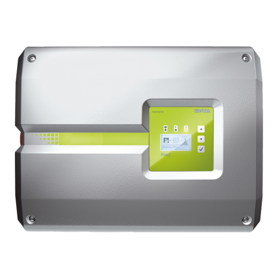
Exterior view of the inverter Fig. 9: PIKO inverter (exterior view) Cover screws Cover Display DC switch Housing Plug connectors for connecting the solar modules Cable openings for optional communication Opening for the mains cable © 2017 KOSTAL Solar Electric GmbH... - Page 22 Device and system description DC switch on the inverter Fig. 10: DC switch ON Fig. 11: DC switch OFF © 2017 KOSTAL Solar Electric GmbH...
- Page 23 Installation position for RS485 overvoltage protection (optional) Installation position for LAN overvoltage protection (optional) Receptacle for overvoltage protection on DC side (optional) Grid and system protection provided by a PIKO EPC AC Off Switch card © 2017 KOSTAL Solar Electric GmbH...
- Page 24 2 Ethernet connections (RJ45) Analog interface terminal RS485 terminal The communication board is the communications centre of the inverter. The connections for communication, the display and the control buttons are located on the communication board. © 2017 KOSTAL Solar Electric GmbH...
- Page 25 Fig. 14: Control panel Display (display dependent upon the inverter type) LEDs for displaying the operational status Control buttons Adjustments can be made and data retrieved via the control panel. Event messages are shown on the display. © 2017 KOSTAL Solar Electric GmbH...
- Page 26 Device and system description The main menu Fig. 15: Main menu "DC" menu "Settings" menu "AC" menu © 2017 KOSTAL Solar Electric GmbH...
- Page 27 This can be obtained from You can log in as a plant owner or as an the Service team. installer. Ch. 11.2 Logout: Menu item to log out of the Webserver. Tab. 2: Overview of the Webserver pages © 2017 KOSTAL Solar Electric GmbH...
- Page 28 PC or sent to a Saving interval Saving time solar portal. 5 minutes Max. 130 days 15 minutes Max. 400 days 60 minutes Max. 1500 days Tab. 3: Saving intervals of data logger © 2017 KOSTAL Solar Electric GmbH...
-
Page 29: Installation
Installation ..........................32 Electrical connection ......................... 35 Central system protection ......................38 Installing overvoltage protection (optional) ................. 40 Connection of solar module ...................... 44 Connection of communication components ................48 Initial commissioning ......................... 52 © 2017 KOSTAL Solar Electric GmbH... -
Page 30: Transport And Storage
(cooling elements) after unpacking. nal packaging. Fig. 16: Recessed grips on inverter Recessed grips have been integrated to the left and right for better transport of the inverter. © 2017 KOSTAL Solar Electric GmbH... -
Page 31: Scope Of Delivery
Plug seals for screw connection of network cable Reducing ring for screw connection of AC cable with a diameter of 15-23 mm 1 x M4×9 lock screw for inverter 2 x LAN overvoltage protection brackets with M4x9 screws © 2017 KOSTAL Solar Electric GmbH... -
Page 32: Installation
-25 °C and +60 °C. -25...60 °C -13...140 °F The air humidity must be between 4 % and 100 % (condensing). 4...100 % Maintain minimum distances to other inverters and the necessary clearance. 90° © 2017 KOSTAL Solar Electric GmbH... - Page 33 Mount inverters on vertical installation surfaces. For this purpose, use the wall mount provided. 90° Install inverters so that they are not accessible to children. Inverters must be easily accessible and the display clearly visible. © 2017 KOSTAL Solar Electric GmbH...
- Page 34 You can find the distances for wall mounting in the following table: Dimensions in mm (inch) Screws Wall mount M4 x 9 min. 6 (0.236 in) / 8.8 (3.9) (7.9) (2.99) (1.8) (0.1) (20) (4.2) (15.8) Fig. 19: Wall mounting of several inverters © 2017 KOSTAL Solar Electric GmbH...
-
Page 35: Electrical Connection
(RCD) or residual current monitoring de- vices (RCM) are used, only type B ≥300 mA RCDs or RCMs are per- mitted on the AC side. Refer to the manufacturer's declaration on our website for exceptions. © 2017 KOSTAL Solar Electric GmbH... - Page 36 If screw connections are not being used, leave the Existing cables and their routing blind plug in the screw connections. within the inverter must not be changed. This can otherwise result in malfunctions in the inverter. © 2017 KOSTAL Solar Electric GmbH...
- Page 37 The dimensioning of the cable cross-section to be used and the cable type must match the local requirements. See "Technical data" chapter Ch. 9.1 Fig. 23: Country-specific PE connection, inside / outside The AC connection is connected. © 2017 KOSTAL Solar Electric GmbH...
-
Page 38: Central System Protection
Switch board, which is activated by the external moni- toring unit, the PIKO inverter switches off immediately as soon as the monitoring unit opens the contact and the external voltage supply is thereby shut down. © 2017 KOSTAL Solar Electric GmbH... - Page 39 Guide control cable into inverter and connect to terminal Fig. 25, It. 2 of printed circuit board (PCB). Connect control cable with external sensor. Move DIP switch to ON position Fig. 25, It. 3 Grid and system protection connected © 2017 KOSTAL Solar Electric GmbH...
-
Page 40: Installing Overvoltage Protection (Optional)
The overvoltage protection modules can be obtained from your service partner, specialist shops or the KOSTAL Solar Electric GmbH online shop. The types which can be used are listed on the following pages in the Info block. If overvoltage protection has been inserted in the... - Page 41 Note the coding at the The following types are approved for plug-in positions. the overvoltage protection and can be ordered from the KOSTAL online shop: DC side: 4 x MOD PV SCI 600 DG (10334450)
- Page 42 Note the manufacturer's installation and assembly instructions for the overvoltage protection. The following types are approved for the overvoltage protection and can be ordered from the KOSTAL online shop: Ethernet connection (LAN): 2 x CLD RJ45B (10324083) Fig. 28: LAN overvoltage protection mount...
- Page 43 The following types are approved for the overvoltage protection and can be ordered from the KOSTAL online shop: RS485 connection: 1 x DCO SD2 ME (RS485) (10330764) Fig. 30: RS485 overvoltage protection in the inverter...
-
Page 44: Connection Of Solar Module
Properly should be designed within the voltage range between mount plugs and sockets. and V . KOSTAL Solar Plan should be MPPmin MPPmax used as a planning tool here. If the output of the solar modules is higher than that... - Page 45 Provide these measured values in the event of a complaint. Failure to do so will make any manufacturer's warranty, guarantee or liability null and void unless you can prove that the damage was not due to non-compliance. © 2017 KOSTAL Solar Electric GmbH...
- Page 46 Ch. 4.3 Check the strings for earth faults and short circuits and correct these where appropriate. DAMAGE POSSIBLE If the PV generators are incorrectly connected, the inverter may be damaged. Check the connections before commissioning. © 2017 KOSTAL Solar Electric GmbH...
- Page 47 Y-splitter, these strings and the parallel string (e.g. DC1/ DC2) must also be protected using separate string fuses. Fig. 32: Overview of DC connections Fig. 33: Connect the PV string The DC side is connected. © 2017 KOSTAL Solar Electric GmbH...
-
Page 48: Connection Of Communication Components
2 Ethernet connections (RJ45) Analog interface terminal Terminal for RS485 interface The communication board is the communications centre of the inverter. The connections for communication, the display and the control buttons are located on the communication board. © 2017 KOSTAL Solar Electric GmbH... - Page 49 Aln3 and Aln4 are inactive. GND: Ground for RS485 RS485 connections A & B: Serial RS485 interfaces A ripple control receiver can nonetheless be connected. for the connection of external data loggers, energy meters, displays and additional inverters. © 2017 KOSTAL Solar Electric GmbH...
- Page 50 (Ethernet 10BaseT, Several inverters can be connected to a network for 10/100 MBit/s), an Ethernet cable of data retrieval. category 6 (Cat 6, FTP) with a max. length of 100 m is to be used. © 2017 KOSTAL Solar Electric GmbH...
- Page 51 Fig. 37: Assignment of RS485 connection sockets RS485 socket: connection of data loggers or other inverters. A connection with other inverters can be established via the RS485 connection. Several inverters can be connected to a network for data retrieval. © 2017 KOSTAL Solar Electric GmbH...
-
Page 52: Initial Commissioning
The screensaver is deactivated when any key is The installation process can vary pressed twice. depending upon the software version of the inverter. The "Language" menu appears on the display. Information on using the menu: Ch. 4.4 © 2017 KOSTAL Solar Electric GmbH... - Page 53 The settings are assumed by the inverter. an installer or by entering the service code. The inverter is in operation and can now be used. Initial commissioning is completed. © 2017 KOSTAL Solar Electric GmbH...
-
Page 54: Operation And Operating The Device
Operational status (display) ....................... 61 Operational status (LEDs) ......................62 The menu structure of the inverter .................... 63 The service menu ........................67 The energy management system in the inverter ................ 68 4.10 Event codes ..........................69 © 2017 KOSTAL Solar Electric GmbH... -
Page 55: Switching On The Inverter
INFO when a key is pressed twice. When no key has been pressed for The inverter is in operation. several minutes, the screensaver with the image of the inverter appears automatically on the display. © 2017 KOSTAL Solar Electric GmbH... -
Page 56: Switching Off The Inverter
Additional steps are necessary for maintenance or repair work on the inverter. Ch. 4.3. Turn the DC switch on the inverter to OFF. Fig. 11 If external DC voltage separators are present, switch off the DC strings consecutively. © 2017 KOSTAL Solar Electric GmbH... -
Page 57: Energising The Inverter
Wait five minutes until the capacitors of the inverter have discharged. Allow the device to cool down. Ensure that all connections are voltage-free. The inverter is de-energised. Work on the inverter or on the feed cables can now be carried out. © 2017 KOSTAL Solar Electric GmbH... -
Page 58: Control Panel
The operating values can be retrieved and settings When no key has been pressed for adjusted on the display. several minutes, the screensaver with the image of the inverter appears automatically on the display. © 2017 KOSTAL Solar Electric GmbH... - Page 59 Back: This function can be used to jump to the higher level menu. Values entered in the menu must be saved in advance, otherwise these will not be adopted. Confirm: Values are adopted or the selected function confirmed with this function. © 2017 KOSTAL Solar Electric GmbH...
- Page 60 To this end, go to after the last character and press an arrow key (the character << appears in the text field). The characters can now be deleted by pressing the "ENTER" key. © 2017 KOSTAL Solar Electric GmbH...
-
Page 61: Operational Status (Display)
Ch. 7, excess temperature, fault) An event is present. Remedial meas- Event code xxxx ures can be found in the "Event Ch. 4.10 codes" chapter Tab. 4: Operational notifications on the display of the inverter © 2017 KOSTAL Solar Electric GmbH... -
Page 62: Operational Status (Leds)
"AC" LED lit green: The green LED signals the feed-in mode of the inverter. No LED is lit: The device is ready for operation, but the input voltage is too low Ch. 9.1. OR: The device is switched off. © 2017 KOSTAL Solar Electric GmbH... -
Page 63: The Menu Structure Of The Inverter
4.7 The menu structure of the inverter Fig. 45: Main menu structure on the display DC menu Settings menu AC menu The menus* are listed individually on the following pages. Deviations due to software versions (UI status) possible. © 2017 KOSTAL Solar Electric GmbH... - Page 64 Total yield (diagram) The following DC inputs are connected in parallel internally in the inverter and are each shown as a string. DC1 (DC1 and DC2), DC2 (DC3 and DC4), DC3 (DC5 and DC6) © 2017 KOSTAL Solar Electric GmbH...
- Page 65 Router IP RS485 settings Bus termination Bus bias voltage RS485 address Portal configuration Portal code Data export Event messages Immediately mailing Device information SW/HW release Serial number Event list Country setting Functional test Fan test © 2017 KOSTAL Solar Electric GmbH...
- Page 66 Following entry of a code, additional menu items for configuring the inverter appear. The code can be requested for installers from the Service team. The Webserver password for the "pvserver" user is reset to the default values "pvwr" . Only visible once the service code has been entered. © 2017 KOSTAL Solar Electric GmbH...
-
Page 67: The Service Menu
Reset inverter to factory setting. All (possible without service settings are deleted apart from the code) country setting. Country setting Reset the country setting. Once the reset is complete, the inverter reports back with the country setting. © 2017 KOSTAL Solar Electric GmbH... -
Page 68: The Energy Management System In The Inverter
EMS then calculates and controls the optimal usage of PV energy. The generated PV energy is primarily used for consum- ers (such as light, washing machine or television). The remaining generated PV energy is fed into the grid and remunerated. © 2017 KOSTAL Solar Electric GmbH... -
Page 69: Event Codes
The type of event can be determined on the basis of the message in the display "Event code: xxxx" and the following table. In the case of events not listed in the table, please con- tact the Service team. © 2017 KOSTAL Solar Electric GmbH... - Page 70 Internal system fault Internal AC system fault Device carries out test several times and generally overrides 3048 Internal communica- Internal communication error Check the internal communica- tion fault tion cables between the individual PCBs © 2017 KOSTAL Solar Electric GmbH...
- Page 71 Internal system fault Internal system error Contact support 3088 Internal system fault Fan unit dirty Clean fan unit 3093 Internal parameteriza- Incorrect parameterization Contact support tion fault 3094 Internal parameteriza- Incorrect parameterization Contact support tion fault © 2017 KOSTAL Solar Electric GmbH...
- Page 72 Support 4110 Internal system fault Internal software error Support 4131 Internal system fault Internal system fault Support 4150 Information Increased grid frequency. Check the installation Frequent recurrence in the morn- ing and the evening. © 2017 KOSTAL Solar Electric GmbH...
- Page 73 Internal system fault Internal system fault Support 4321 Internal parameteriza- Defective EEPROM, forbidden Support tion fault memory access 4322 Internal parameteriza- Software error Contact support tion fault 4323 Internal parameteriza- Residual current Support tion fault © 2017 KOSTAL Solar Electric GmbH...
- Page 74 Internal system fault Support 4850 Internal system fault Energy supply company Support 4870 Internal system fault Internal system fault Support - 4909 Tab. 5: Event codes If the error occurs several times/permanently, please contact Support. © 2017 KOSTAL Solar Electric GmbH...
- Page 75 Operation and operating the device Legend for the "Event codes" table LEDs flashing LEDs lit up LEDs off © 2017 KOSTAL Solar Electric GmbH...
-
Page 76: Webserver
Connecting the inverter and computer ..................79 Calling up Webserver ........................ 80 Disconnecting the inverter from the computer ................81 Menu structure in Webserver ....................82 Webserver main menu ......................84 Webserver submenus ....................... 85 © 2017 KOSTAL Solar Electric GmbH... -
Page 77: The Webserver
The statis- tics provide a summary of the yield and operating dura- tion and also provide the log data, which supplies other information. The inverter can also be quickly and easily configured in the Settings. © 2017 KOSTAL Solar Electric GmbH... -
Page 78: Using The Webserver
You can reach the "LAN settings" via the control INFO panel: Control Panel >> Internet options >> Tab: The control panel can be called up "Connections" >> LAN settings. under Windows 10 by right-clicking on the Windows symbol. © 2017 KOSTAL Solar Electric GmbH... -
Page 79: Connecting The Inverter And Computer
Connect the Ethernet cable to the computer. Close the inverter cover. Activate fuses and DC switch. The inverter is connected to the computer. © 2017 KOSTAL Solar Electric GmbH... -
Page 80: Calling Up Webserver
This can be requested from the Service team. Ch. 11.2 Should you forget the password, this can be reset to the default values on the inverter by going to Service menu > "Reset web login". Ch. 4.8 © 2017 KOSTAL Solar Electric GmbH... -
Page 81: Disconnecting The Inverter From The Computer
The inverter is once again in operation. DANGER RISK OF DEATH DUE TO ELECTRI- CAL SHOCK AND DISCHARGE! De-energise the device, secure it against being restarted and wait five minutes so that the capacitors can discharge. Ch. 4.3 © 2017 KOSTAL Solar Electric GmbH... -
Page 82: Menu Structure In Webserver
Displays the function of the S0 input and the associ- ated values Statistics menu Statistics Displays yield for the current day Total Displays total yield Log data Displays the history/log data stored in the inverter © 2017 KOSTAL Solar Electric GmbH... - Page 83 Displays the events in the inverter Versions Displays the serial number, article number, country setting and user interface/firmware/hardware/PAR version of the inverter Logout menu Logout Logging out of the inverter These settings are only possible with a service code © 2017 KOSTAL Solar Electric GmbH...
-
Page 84: Webserver Main Menu
Login: Log into the Webserver. You can log in as a plant owner or as an installer. As an installer you require a service code, which gives you additional setting options on the inverter. Logout: Menu item to log out of the Webserver. © 2017 KOSTAL Solar Electric GmbH... -
Page 85: Webserver Submenus
DC input PV generators. Power values - Shows how much power is fed into output power the public grid. Status - operating Operational status of inverter. For Ch. 4.4. status more information, see © 2017 KOSTAL Solar Electric GmbH... - Page 86 The "Number of energy pulses" shows the number of energy pulses per time unit on the S0 interface. If an external energy meter is connected at the S0 input, for example, the energy counted by the meter can be queried. © 2017 KOSTAL Solar Electric GmbH...
- Page 87 If the inverter is not connected to a The data (LogDaten.dat) are saved on your hard solar portal, regular backup copies of drive. After saving, this data can be displayed and the log data should be created. further processed. © 2017 KOSTAL Solar Electric GmbH...
- Page 88 Access with the serial number remains possible. Date/time Enter the time and date. It is possi- ble to adopt the PC time using the button "Set to PC time". Login Change current password © 2017 KOSTAL Solar Electric GmbH...
- Page 89 DNS server is issued Subnet mask: 255.255.255.0 through the "Manually" setting, the IP address for this is displayed under Router/Gateway: 168.192.2.1 DNS Server 2. DNS Server 1: 168.192.2.1 DNS Server 2: 0.0.0.0 MAC address: 00:80:41:ae:fd:7e © 2017 KOSTAL Solar Electric GmbH...
- Page 90 Protocol: Selection of protocol used on the bus. KOSTAL: Is used to make more PIKO INFO inverters or an external data logger/ energy manager accessible via the A precise description of the protocol interface.
- Page 91 Ch. 8.6. internal memory is full, the oldest data will be overwritten. Plant configuration This function is not supported by this device. Switched output This function is not supported by this device. © 2017 KOSTAL Solar Electric GmbH...
- Page 92 Webserver. Function Meaning User interface version Firmware version Hardware version Version of set of parameters Serial number Inverter serial number Article number Article number of the inverter Country setting Shows the inverter's country setting © 2017 KOSTAL Solar Electric GmbH...
-
Page 93: System Monitoring
Navibutton Verlinkung Kapitel 6 6. System monitoring Creating connection between computer and inverter ..............94 The log data ..........................97 Retrieving, saving and graphically depicting log data ............... 100 © 2017 KOSTAL Solar Electric GmbH... -
Page 94: Creating Connection Between Computer And Inverter
Retrieve log data of the inverter. Inverter and computer can be connected with the follow- ing variants: Variant 1 Page 95 Connect inverter and computer Variant 2 Page 95 Connect inverter and computer by way of a switch/ hub/router © 2017 KOSTAL Solar Electric GmbH... - Page 95 Fig. 50: Connect inverter and computer by way of a router Inverter Ethernet cable Switch/hub/router with or without WLAN Computer via LAN or WLAN (for configuration or data retrieval) © 2017 KOSTAL Solar Electric GmbH...
- Page 96 IP addresses and the network configuration in a network. If the IP address has to be set manually, this can be done in the inverter menu below or above the Webserver under "Communication". © 2017 KOSTAL Solar Electric GmbH...
-
Page 97: The Log Data
The log data can be used for the following purposes: Check operating characteristics of the system Determine and analyse errors Download and graphically depict yield data Fig. 51: Example screen "The log file" File header Physical variables Entries in the log file © 2017 KOSTAL Solar Electric GmbH... - Page 98 Counting unit in points [digits] Counting unit in points [digits] Time Time in seconds [sec] since the inverter was put into operation Temperature in Celsius [°C] Without function Tab. 7: Physical variables in the log file © 2017 KOSTAL Solar Electric GmbH...
- Page 99 Home consumption: Energy currently used in the household in kWh Iso R Insulation resistance in kOhm when switching to AC grid Event POR event, "power on reset": Renewed start-up of communication after a loss of AC voltage. Tab. 8: Log data © 2017 KOSTAL Solar Electric GmbH...
-
Page 100: Retrieving, Saving And Graphically Depicting Log Data
A solar portal has the following functions, which, how- ever, may differ depending upon the portal: Graphic depiction of performance data Worldwide online access to the portal Email notification of errors Data export (e.g. Excel file) Long-term storage of log data © 2017 KOSTAL Solar Electric GmbH... - Page 101 "Code:" field. The portal code can also be assigned wireless connection). via the Webserver under "Portal configuration". The portal code for the PIKO Solar Portal (www.piko-solar-portal.de) is P3421. Portal configuration Data export Code: Fig. 52: Entry of the portal code © 2017 KOSTAL Solar Electric GmbH...
- Page 102 The data transfer to the solar portal is active (rec- ognisable from the X in front of "Data export"). The name of the solar portal is displayed. The data export to the solar portal is being executed. © 2017 KOSTAL Solar Electric GmbH...
-
Page 103: Active Power Control
7. Active power control Why active power control? ...................... 104 Limitation of the PV feed-in capacity ..................105 Active power control with a ripple control receiver ..............106 Installing the ripple control receiver ..................107 © 2017 KOSTAL Solar Electric GmbH... -
Page 104: Why Active Power Control
PV power at the grid connection check to determine which of the two point possibilities offers the better energy yield. Active power control with a ripple control receiver by the energy supply company © 2017 KOSTAL Solar Electric GmbH... -
Page 105: Limitation Of The Pv Feed-In Capacity
(e.g. 70 %). Ask your energy supply company what power limitation applies to you. The power limitation is carried out in your inverter with the PARAKO parameterization software. This software is available from Support. © 2017 KOSTAL Solar Electric GmbH... -
Page 106: Active Power Control With A Ripple Control Receiver
However, the provisions of the energy supply company must be observed. 100 % 60 % 30 % Fig. 53: Active power control with a ripple control receiver Ripple control receiver Control electronics of the inverter © 2017 KOSTAL Solar Electric GmbH... -
Page 107: Installing The Ripple Control Receiver
7.4 Installing the ripple control receiver Fig. 54: Configuration of the ripple control receiver with several inverters (Ethernet networking) Master inverter Additional inverters (slaves) Ethernet or RS485 cable 5-conductor connection Ripple control receiver Energy supply company © 2017 KOSTAL Solar Electric GmbH... - Page 108 The ripple control receiver may only be connected at the master inverter. Fig. 54 100% Fig. 55: Connection of ripple control receiver Analog interface terminal (10-pin) Ripple control receiver Cable The ripple control receiver is connected. © 2017 KOSTAL Solar Electric GmbH...
- Page 109 The active power control for the ripple control tion/Network settings 2". receiver is active. Additional entry options in the address line of the browser: S and the serial number of the inverter on the type plate (example: http://S12345FD323456) © 2017 KOSTAL Solar Electric GmbH...
-
Page 110: Maintenance
8. Maintenance Maintenance and service ......................111 Fan cleaning ........................... 112 Update software (communication board) ................. 116 Update software (inverter firmware) ..................118 Update software (country settings) ..................120 Replacing optional overvoltage protection ................122 © 2017 KOSTAL Solar Electric GmbH... -
Page 111: Maintenance And Service
Service and warranty conditions). Always mount inverters in such a way that falling parts cannot fall into the inverter through the ven- tilation grill or mount the optional fan cover. © 2017 KOSTAL Solar Electric GmbH... -
Page 112: Fan Cleaning
Maintenance 8.2 Fan cleaning Fig. 56: Fan disassembly overview Fan cable Fan grill Fastening straps © 2017 KOSTAL Solar Electric GmbH... - Page 113 Fig. 57: Loosen fan grill Press the fastening straps toward the centre of the fan with a second screwdriver. Pull the fan unit slightly forward. Fig. 58 Fig. 58: Loosen fastening straps © 2017 KOSTAL Solar Electric GmbH...
- Page 114 Fig. 59: Pull out fan cable The fan can also be pulled off the fan grill. To do this, press the fastening straps slightly outward and pull off the fan. Fig. 60 Fig. 60: Disassembly of the fan grill © 2017 KOSTAL Solar Electric GmbH...
- Page 115 Reconnect the fan cable and insert the fan into the housing. When switching on for the first time, check whether the air from the fan is drawn inwards. Start up the inverter Ch. 4.1 © 2017 KOSTAL Solar Electric GmbH...
-
Page 116: Update Software (Communication Board)
Ch. 4.3 Important! After de-ener- The update may take up to 10 minutes. Following the gising the device, wait five minutes update, the message "Update successful" appears for the capacitors to discharge. on the display of the inverter. © 2017 KOSTAL Solar Electric GmbH... - Page 117 Do this by going to: Settings > Device information > SW/HW release Check the time on the inverter and correct this if necessary. Do this by going to: Settings > Basic settings > Date/time. © 2017 KOSTAL Solar Electric GmbH...
-
Page 118: Update Software (Inverter Firmware)
"Update successful" appears back on. on the display of the inverter. Ch. 4.3 Important! After de-ener- gising the device, wait five minutes for the capacitors to discharge. © 2017 KOSTAL Solar Electric GmbH... - Page 119 Following successful installation of the firmware (FW), Following a successful update, the you can retrieve the current version on the inverter. inverter automatically returns to feed- Do this by going to: in mode. Settings > Device information > SW/HW release. © 2017 KOSTAL Solar Electric GmbH...
-
Page 120: Update Software (Country Settings)
Ch. 4.3 Important! After de-ener- gising the device, wait five minutes for the capacitors to discharge. © 2017 KOSTAL Solar Electric GmbH... - Page 121 Maintenance The inverter will restart when the update has been successful. If the update was unsuccessful, carry it out again or contact the Service team. The update has been carried out. © 2017 KOSTAL Solar Electric GmbH...
-
Page 122: Replacing Optional Overvoltage Protection
8.6 Replacing optional overvoltage protection The overvoltage protection modules can be obtained from your service partner, specialist shops or the KOSTAL Solar Electric GmbH online shop. The types which can be used are listed on the following pages in the Info block. - Page 123 The following types are approved for the overvoltage protection and can be ordered from the KOSTAL online Fig. 62: Installation positions for DC overvoltage protection shop: Overvoltage protection for DC side 4 x...
- Page 124 Note the manufacturer's installation and assembly instructions for the overvoltage protection. The following types are approved for the overvoltage protection and can be ordered from the KOSTAL online shop: Ethernet connection (LAN): 2 x CLD RJ45B (10324083) Problems in communication with the inverter indicate defective modules.
- Page 125 Plug the communication overvoltage protection. cables into the module. The following types are approved for the overvoltage protection and can be ordered from the KOSTAL online shop: RS485 connection: 1 x DCO SD2 ME (RS485) (10330764) Problems in communication with the inverter indicate a defective module.
-
Page 126: Technical Data
Navigation button, link to chapter 10 9. Technical data Technical data ......................... 127 Block diagram ........................132 © 2017 KOSTAL Solar Electric GmbH... -
Page 127: Technical Data
Technical data 9.1 Technical data Subject to technical changes. Errors excepted. You can find current information at www.kostal-solar-electric.com. Inverter Unit PIKO 36 EPC Input side Inverter type PIKO EPC Max. PV power (cos φ = 1) Rated input voltage (U DC,r Max. - Page 128 Setting range of the power factor cos φ 0.8...1...0.8 AC,r Power factor for rated power (cos φ AC,r Max. total harmonic distortion Device properties Standby night-time consumption Efficiency Max. efficiency 98.7 European efficiency 98.3 Californian efficiency 98.4 MPP efficiency 99.9 © 2017 KOSTAL Solar Electric GmbH...
- Page 129 Compatibility with external residual current protection devices RCD type B, RCM type B Internal operator protection according to EN 62109-2 RCMU/RCCB type B Automatic switching device integrated (ENS) Electronic DC disconnection device integrated Reverse polarity protection, DC-side © 2017 KOSTAL Solar Electric GmbH...
- Page 130 RD661, PO 12.3, G59/3-2, IEC 62116, IEC 61727, EN 50438*, CLC/TS 50549-1, TSE K 191, CLC/TS 50549-2, TSE K 192, TOR D4, ERDF-PRO-RES 64E (*does not apply to all national annexes of EN 50438) © 2017 KOSTAL Solar Electric GmbH...
- Page 131 Automatic disconnection device to VDE V 0126-1-1, for Austria: The inverter is equipped "With automatic disconnection device in accordance with ÖVE/ÖNORM E 8001-4-712". The inverter's terminals are only suitable for copper cables. © 2017 KOSTAL Solar Electric GmbH...
-
Page 132: Block Diagram
Grid monitoring and shut-down control panel Grid monitoring and shut-down Central grid and system protection interface ( circuit breaker ) 3-phase AC output Optional AC overvoltage protection Display and communication Inverter bridge Intermediate circuit System control with MPP trackers © 2017 KOSTAL Solar Electric GmbH... -
Page 133: Accessories
Navibutton Verlinkung Kapitel 11 10. Accessories 10.1 Additional accessories ......................134 © 2017 KOSTAL Solar Electric GmbH... -
Page 134: Additional Accessories
Accessories 10.1 Additional accessories PIKO M2M Service The PIKO M2M Service allows KOSTAL customers to monitor a PV system using a mobile link to the PIKO Solar Portal for continuous system monitoring. A secure and encrypted VPN connection which only... - Page 135 A special feature: The measuring values can be visual- ised via a solar portal (e.g. PIKO Solar Portal). You can find additional information about this product on our website www.kostal-solar-electric.com under the category Products/Monitoring. © 2017 KOSTAL Solar Electric GmbH...
- Page 136 AC side: from our KOSTAL online shop. 3 x MOD 275 (10324116) Ethernet connection (LAN): You will find the KOSTAL online shop on our homepage 2 x CLD RJ45B (10324083) at www.kostal-solar-electric.com. RS485 connection: 1 x DCO SD2 ME (RS485) (10330764)
-
Page 137: Appendix
Navibutton Verlinkung Kapitel 12 11. Appendix 11.1 Type plate ..........................138 11.2 Warranty and service ......................139 11.3 Handover to the operator ......................140 11.4 Disassembly and disposal ....................... 141 © 2017 KOSTAL Solar Electric GmbH... -
Page 138: Type Plate
Version number of the user inverter. You will find the device type and the most interface of the device important technical data listed on the type plate. Date of last update (only for service devices) Removable warranty label © 2017 KOSTAL Solar Electric GmbH... -
Page 139: Warranty And Service
Language: English, Turkish +41 32 5800 225 France, Belgium, Luxembourg +33 16138 4117 Greece +30 2310 477 555 Italy +39 011 97 82 420 Spain, Portugal +34 961 824 927 Turkey +90 212 803 06 26 © 2017 KOSTAL Solar Electric GmbH... -
Page 140: Handover To The Operator
Position and function of the AC line circuit breaker Safety when handling the device Appropriate procedure when checking and servicing the unit Meaning of the LEDs and the display messages Contact person in the event of a fault © 2017 KOSTAL Solar Electric GmbH... -
Page 141: Disassembly And Disposal
This equipment can be handed in to waste collection points free of charge. Find out about the local requirements for the separate collection of electrical and electronic equipment in your country. © 2017 KOSTAL Solar Electric GmbH... -
Page 142: Index
DC connections ............................35, 47, 57 DC switch ..........................22, 52, 55, 56, 57, 132 DHCP server ..............................89, 96 Directives ................................130 Display ........................33, 52, 58, 59, 60, 61, 63, 69 Disposal ................................141 © 2017 KOSTAL Solar Electric GmbH... - Page 143 IP address ........................... 65, 78, 80, 89, 96, 109 LAN ................................50, 78 Language ................................ 2, 65 LAN overvoltage protection ......................... 42, 124 Line circuit breaker ..........................35, 52, 55, 57 Log data ............................ 80, 87, 97, 99, 100 © 2017 KOSTAL Solar Electric GmbH...
- Page 144 Ripple control receiver ......................49, 88, 107, 108, 109 RJ45 ..........................24, 50, 51, 79, 108, 130 Router ................................50, 65 RS485 ..........................49, 51, 65, 89, 107, 130 RS485 overvoltage protection ........................43, 125 © 2017 KOSTAL Solar Electric GmbH...
- Page 145 Type plate ..........................69, 80, 109, 138, 139 User name ..............................80, 109 Wall mount ............................31, 34, 141 Warnings ................................14 Warranty ............................9, 45, 130, 139 Webserver ....................... 27, 77, 78, 80, 88, 94, 95, 109 © 2017 KOSTAL Solar Electric GmbH...
- Page 146 79108 Freiburg i. Br. Deutschland Telefon: +49 761 47744 - 100 Fax: +49 761 47744 - 111 KOSTAL Solar Electric Ibérica S.L. Edifi cio abm Ronda Narciso Monturiol y Estarriol, 3 Torre B, despachos 2 y 3 Parque Tecnológico de Valencia 46980 Valencia España...
Need help?
Do you have a question about the PIKO 36 EPC and is the answer not in the manual?
Questions and answers