Kostal PIKO 10 Operating Manual
Hide thumbs
Also See for PIKO 10:
- Operating manual (167 pages) ,
- Operating manual (157 pages) ,
- Quick start manual (6 pages)
Table of Contents
Advertisement
Quick Links
Advertisement
Table of Contents

Related Manuals for Kostal PIKO 10


Summary of Contents for Kostal PIKO 10
- Page 1 Homepage_Cover Operating manual PIKO inverter 10-20...
- Page 2 General note on gender equality KOSTAL Solar Electric GmbH is aware of the importance of language with regard to the equality of women and men and always makes an effort to reflect this in the documentation.
-
Page 3: Table Of Contents
Operational status (display) ....................... 62 Operational status (LEDs) ......................63 The menu structure of the inverter .................... 64 The service menu ........................68 The energy management system in the inverter ................ 69 4.10 Event codes ..........................70 © 2019 KOSTAL Solar Electric GmbH... - Page 4 Setting up self-consumption control in the Webserver ............117 Maintenance Maintenance and service ......................125 Housing cleaning ........................126 Fan cleaning ........................... 127 Update software (communication board) ................131 Update software (inverter firmware) ..................133 Update software (country settings) ..................135 © 2019 KOSTAL Solar Electric GmbH...
- Page 5 Technical data 10.1 Technical data ........................137 10.2 Block diagram ........................142 Accessories 11.1 Installation of the KOSTAL Smart Energy Meter ..............144 11.2 Additional accessories ......................147 Appendix 12.1 Type plate ..........................150 12.2 Warranty and service ......................151 12.3 Handover to the operator .......................
-
Page 6: General Information
1. General information Proper use ..........................8 EU declarations of conformity ....................10 About this manual ........................11 Notes in this manual ......................... 13 Symbols used ........................... 17 Labels on the inverter ....................... 18 © 2019 KOSTAL Solar Electric GmbH... - Page 7 General information Thank you for choosing a PIKO inverter from KOSTAL Solar Electric GmbH! We hope you enjoy consistently high energy yields with the PIKO inverter and your photovoltaic system. If you have any technical questions, please call our service hotline: Germany and other countries...
-
Page 8: Proper Use
The inverter may therefore only be used for its intended purpose. All components fitted on the inverter or in the PV system must satisfy the standards and guidelines that apply in the country of installation. © 2019 KOSTAL Solar Electric GmbH... - Page 9 Factory settings may only be changed by qualified electrical installers or persons with at least comparable or higher technical qualifications, e.g. foremen, technicians or engineers. When doing so, all requirements are to be observed. © 2019 KOSTAL Solar Electric GmbH...
-
Page 10: Eu Declarations Of Conformity
General information 1.2 EU declarations of conformity KOSTAL Solar Electric GmbH hereby declares that the inverter described in this document complies with the basic requirements and other relevant conditions of the directives listed below. Directive 2014/30/EU (on the approximation of the laws of the Member States relating to electromagnetic compatibility... -
Page 11: About This Manual
Read this manual carefully in its entirety. It contains important information on the installation and operation of the inverter. Pay particular attention to the instructions regarding safe usage. KOSTAL Solar Electric GmbH assumes no liability for damages arising from the non-observance of this manual. - Page 12 Calling up the main table of contents Navigation bar Tables of contents You can navigate to the referenced points in the document within the instruction text using the cross-references. Ch. 1 Fig. 1, It. 2 Fig. 2: Examples of cross-references © 2019 KOSTAL Solar Electric GmbH...
-
Page 13: Notes In This Manual
Information note Other notes Notes have been incorporated into the instruction text. A differentiation is made in this manual between warnings and information notes. All notes are identified in the text line with an icon. © 2019 KOSTAL Solar Electric GmbH... - Page 14 Fig. 4: Structure of the warnings Warning symbol Signal word Type of danger Corrective actions Warning symbols Danger Danger due to electrical shock and discharge Danger due to electromagnetic fields Danger due to burns © 2019 KOSTAL Solar Electric GmbH...
- Page 15 IMPORTANT INFORMATION The inverter may only be installed, operated, maintained and repaired by trained and qualified staff. Fig. 5: Example of an information note © 2019 KOSTAL Solar Electric GmbH...
- Page 16 Damage to property possible Other notes They contain additional information or tips. INFO This is additional information. Fig. 6: Example of an information note Symbols within the additional notes Information or tip Enlarged view © 2019 KOSTAL Solar Electric GmbH...
-
Page 17: Symbols Used
Final result of a handling instruction Cross-reference to other places in the document Æ or to other documents List Tab. 1: Symbols and icons used Abbreviations used Abbreviation Explanation Tab. Table Fig. Figure Item Chapter © 2019 KOSTAL Solar Electric GmbH... -
Page 18: Labels On The Inverter
5 min shut-down Danger due to burns 5 min Danger notice Additional earth connection Observe and read operating manual Device may not be disposed of with household waste. Observe the local application of disposal requirements © 2019 KOSTAL Solar Electric GmbH... -
Page 19: Device And System Description
Navibutton Verlinkung Kapitel 02 2. Device and system description The photovoltaic system ......................20 Inverter components ......................... 21 Inverter functions ........................29 © 2019 KOSTAL Solar Electric GmbH... -
Page 20: The Photovoltaic System
Fig. 8: Photovoltaic system 3-phase Inverter PV generators (number depends on the type) Line circuit breaker for inverter Optional accessories KOSTAL Smart Energy Meter in grid connection position Main fuse building Feed-in procurement meter or smart meter Public grid Line circuit breaker for energy consumers... -
Page 21: Inverter Components
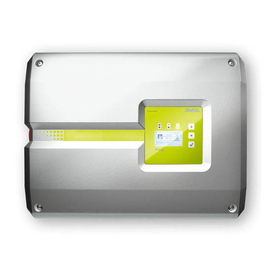
2.2 Inverter components Exterior view of the inverter Fig. 9: PIKO inverter Cover screws Cover Display DC switch Housing Plug connector for solar modules Wall mount Cable openings for optional communication Opening for the mains cable © 2019 KOSTAL Solar Electric GmbH... - Page 22 Device and system description DC switch on the inverter Fig. 10: DC switch ON Fig. 11: DC switch OFF © 2019 KOSTAL Solar Electric GmbH...
- Page 23 Fig. 13: PIKO inverters 15 - 20 (interior view) Communication board Ethernet connections LAN (RJ45) Terminal for analogue interface/RS485 Cable tray with fastening openings AC terminal Grid and system protection via KOSTAL Smart AC Switch board (only PIKO 15-20) © 2019 KOSTAL Solar Electric GmbH...
- Page 24 2 Ethernet connections LAN (RJ45) Analogue interface terminal RS485 terminal The communication board is the communications centre of the inverter. The connections for communication, the display and the control buttons are located on the communication board. © 2019 KOSTAL Solar Electric GmbH...
- Page 25 Here it is the menu of the 3-phase inverter) LEDs for displaying the operational status Control buttons Adjustments can be made and data retrieved via the control panel. Event messages are shown on the display. © 2019 KOSTAL Solar Electric GmbH...
- Page 26 Device and system description The main menu Fig. 16: Main menu: 3-phase "DC" menu "Settings" menu "AC" menu © 2019 KOSTAL Solar Electric GmbH...
- Page 27 You need a service code to log in as Logout: Menu item to log out of the an installer. This can be obtained from Webserver. the Service team. Ch. 12.2 Tab. 2: Overview of the Webserver pages © 2019 KOSTAL Solar Electric GmbH...
- Page 28 PC or sent to a Saving interval Saving time solar portal. 5 minutes Max. 130 days 15 minutes Max. 400 days 60 minutes Max. 1500 days Tab. 3: Saving intervals of data logger © 2019 KOSTAL Solar Electric GmbH...
-
Page 29: Inverter Functions
PV module, the performance of every single module is optimised so that they all deliver optimum performance. The PIKO inverter allows such PV modules to be connected and adapts its own control to this. For more information Ch. 5.6 © 2019 KOSTAL Solar Electric GmbH... - Page 30 Meter, 24-hour monitoring of home consumption or feed-in to the public grid can be displayed via the online interface of the KOSTAL Smart Energy Meter or KOSTAL Solar Portal. This information is not shown in the inverter. You will find more information about using the KOSTAL Smart Energy Meter in Ch.
- Page 31 The PIKO 15-20 has a KOSTAL Smart AC Switch integrated as standard. This can take the place of the external circuit breaker and save you money.
-
Page 32: Installation
Transport and storage ....................... 33 Scope of delivery ........................34 Installation ..........................35 Electrical connection ......................... 38 Central system protection ......................41 Connection of solar module ...................... 43 Connection of communication components ................48 Initial commissioning ......................... 52 © 2019 KOSTAL Solar Electric GmbH... -
Page 33: Transport And Storage
If stored for a longer period before installation, all inverter components must be kept dry and dust-free in the original packaging. Fig. 17: Recessed grips on inverter Recessed grips have been integrated to the left and right for better transport of the inverter. © 2019 KOSTAL Solar Electric GmbH... -
Page 34: Scope Of Delivery
1 x plug seal for screw connection of network cable 2 x wire jumpers for parallel connection 1 x plug seal for screw attachment of AC cable with a max. diameter of 14.5 mm (only for PIKO 15-20) © 2019 KOSTAL Solar Electric GmbH... -
Page 35: Installation
°80C during operation. Select the explosive areas in the vicinity must be installation site in accordance with ensured. the information provided in these instructions. Always keep the ventilation openings clear. © 2019 KOSTAL Solar Electric GmbH... - Page 36 -20 °C and +60 °C. The air humidity must be between 4 % and 100 % (condensing). Install inverters so that they are not accessible to children. Inverters must be easily accessible and the display clearly visible. © 2019 KOSTAL Solar Electric GmbH...
- Page 37 (7.9) (2.6) (1.4) (0.1) (16) (4.4) (13.2) PIKO 15 - 20 M4 x 9 min. 6 (0.236 in) / 8.8) (3.9) (7.9) (2.99) (1.8) (0.1) (20) (4.2) (15.8) Fig. 20: Wall mounting of several inverters © 2019 KOSTAL Solar Electric GmbH...
-
Page 38: Electrical Connection
(RCD) or residual current monitoring devices (RCM) are used, only type B RCDs or RCMs are permitted on the AC side. Refer to the manufacturer's declaration on our website for exceptions. © 2019 KOSTAL Solar Electric GmbH... - Page 39 See the "Technical Data" chapter for the dimensioning of the required AC line circuit breaker PIKO 10 = 4 - 6 mm² 15 mm and the cable cross-sections to be PIKO 12 = 4 - 6 mm² 15 mm used.
- Page 40 The dimensioning of the cable cross-section to be used and the cable type must match the local requirements. See "Technical data" chapter Fig. 24: Country-specific PE connection Ch. 10.1 The AC connection is connected. © 2019 KOSTAL Solar Electric GmbH...
-
Page 41: Central System Protection
If external grid and system protection is used, the KOSTAL Smart AC Switch board in the inverter can be used as the switching element, which provides the function of a circuit breaker in conjunction with the inverter's certified grid and system protection function. - Page 42 Installation Connecting control cable with external sensor 5-12V DC ON √ Fig. 26: KOSTAL Smart AC Switch board KOSTAL Smart AC Switch board Terminal for control cable (5-12 V DC) ON/OFF function switch Control cable for external monitoring unit Guide control cable into inverter and connect to terminal Fig.
-
Page 43: Connection Of Solar Module
Properly mount plugs and sockets. should be designed within the voltage range between and U . KOSTAL Solar Plan should be MPPmin MPPmax used as a planning tool here. If the output of the solar modules is higher than that... - Page 44 Only the inputs DC1 and DC2 can be connected in parallel. IMPORTANT INFORMATION When more than 2 strings are connected in parallel, a string fuse may need to be installed. To this purpose, observe the information of the module manufacturer. © 2019 KOSTAL Solar Electric GmbH...
- Page 45 IMPORTANT Parallel connection has been set up INFORMATION Following the initial installation, the parallel connection can still be changed in the inverter by going to Settings > Service menu > String configuration. © 2019 KOSTAL Solar Electric GmbH...
- Page 46 Check the strings for earth faults and short circuits can discharge. Ch. 4.3 and correct these where appropriate. DAMAGE POSSIBLE If the PV generators are incorrectly connected, the inverter may be damaged. Check the connections before commissioning. © 2019 KOSTAL Solar Electric GmbH...
- Page 47 Plug the sockets and plugs of the DC cables onto the inverter. Fig. 31 Keep the plug seals out of the plug connectors. Fig. 31: Connect the PV string The DC side is connected. © 2019 KOSTAL Solar Electric GmbH...
-
Page 48: Connection Of Communication Components
The connections for communication, the display and the control buttons are located on the communication board. The communication board is covered by a protective film over the S0/AL Out terminal. This can be lifted up for installation. © 2019 KOSTAL Solar Electric GmbH... - Page 49 It closes when the set conditions are fulfilled. In the Webserver, go to "Settings" > "Switched output". In the “Switched output function” field, select the option “Self-consumption control”. Click on "Accept". The "Self-consumption control" function is activated. © 2019 KOSTAL Solar Electric GmbH...
- Page 50 RS485 connections A & B: Serial RS485 interfaces analogue inputs Aln3 and Aln4 are for the connection of external data loggers, Modbus inactive. energy meters, displays and additional inverters. A ripple control receiver can nonetheless be connected. © 2019 KOSTAL Solar Electric GmbH...
- Page 51 For connection with a computer or computer network (Ethernet 10BaseT, for data retrieval. 10/100 MBit/s), an Ethernet cable of category 6 (Cat 6, FTP) with a max. length of 100 m is to be used. © 2019 KOSTAL Solar Electric GmbH...
-
Page 52: Initial Commissioning
Switch the DC switch of the inverter to ON. inside the housing from seizing. Fig. 10 If external DC voltage separators are present, activate the DC strings consecutively. The screensaver appears on the display and displays the device type. © 2019 KOSTAL Solar Electric GmbH... - Page 53 Depending upon the wiring of the DC inputs, activate inputs. and confirm the parallel connection. The "Country setting" menu appears on the display. Select and confirm the desired country/standard/ directive. A confirmation field for the “Country setting” appears on the display. © 2019 KOSTAL Solar Electric GmbH...
- Page 54 The settings are assumed by the inverter. It is no longer possible to change the country setting once it has been The inverter is in operation and can now be used. Initial confirmed. commissioning is completed. © 2019 KOSTAL Solar Electric GmbH...
-
Page 55: Operation And Operating The Device
Operational status (display) ....................... 62 Operational status (LEDs) ......................63 The menu structure of the inverter .................... 64 The service menu ........................68 The energy management system in the inverter ................ 69 4.10 Event codes ..........................70 © 2019 KOSTAL Solar Electric GmbH... -
Page 56: Switching On The Inverter
INFO when a key is pressed twice. When no key has been pressed for The inverter is in operation. several minutes, the screensaver with the image of the inverter appears automatically on the display. © 2019 KOSTAL Solar Electric GmbH... -
Page 57: Switching Off The Inverter
Additional steps are necessary for maintenance or repair work on the inverter. Ch. 4.3. Turn the DC switch on the inverter to OFF. Fig. 11 If external DC voltage separators are present, switch off the DC strings consecutively. © 2019 KOSTAL Solar Electric GmbH... -
Page 58: Energising The Inverter
Wait five minutes until the capacitors of the inverter have discharged. Allow the device to cool down. Ensure that all connections are voltage-free. The inverter is de-energised. Work on the inverter or on the feed cables can now be carried out. © 2019 KOSTAL Solar Electric GmbH... -
Page 59: Control Panel
The operating values can be retrieved and settings When no key has been pressed for adjusted on the display. several minutes, the screensaver with the image of the inverter appears automatically on the display. © 2019 KOSTAL Solar Electric GmbH... - Page 60 Back: This function can be used to jump to the higher level menu. Values entered in the menu must be saved in advance, otherwise these will not be adopted. Confirm: Values are adopted or the selected function confirmed with this function. © 2019 KOSTAL Solar Electric GmbH...
- Page 61 To this end, go to after the last character and press an arrow key (the character << appears in the text field). The characters can now be deleted by pressing the "ENTER" key. © 2019 KOSTAL Solar Electric GmbH...
-
Page 62: Operational Status (Display)
Ch. 7, excess temperature, fault) An event is present. Remedial Event code xxxx measures can be found in the "Event codes" chapter Ch. 4.10 Tab. 4: Operational notifications on the display of the inverter © 2019 KOSTAL Solar Electric GmbH... -
Page 63: Operational Status (Leds)
"AC" LED lit green: The green LED signals the feed-in mode of the inverter. No LED is lit: The device is ready for operation, but the input voltage is too low Ch. 10.1. OR: The device is switched off. © 2019 KOSTAL Solar Electric GmbH... -
Page 64: The Menu Structure Of The Inverter
4.7 The menu structure of the inverter Fig. 42: Main menu structure on the display DC menu Settings menu AC menu The menus* are listed individually on the following pages. Deviations due to software versions (UI status) possible. © 2019 KOSTAL Solar Electric GmbH... - Page 65 Operation time (h) Grid parameter Limitation on (%) Grid frequency (Hz) φ Daily yield (diagram) Monthly yield (diagram) Annual yield (diagram) Total yield (diagram) DC inputs depending on device type phases depending on device type © 2019 KOSTAL Solar Electric GmbH...
- Page 66 Router IP RS485 settings Bus termination Bus bias voltage RS485 address Portal configuration Portal code Data export Event messages Immediately mailing Device information SW/HW release Serial number Event list Country setting Functional test Fan test © 2019 KOSTAL Solar Electric GmbH...
- Page 67 The parallel connection menu item is only visible for inverters with at least 2 DC inputs. The Webserver password for the "pvserver" user is reset to the default values "pvwr" . Only visible once the service code has been entered. © 2019 KOSTAL Solar Electric GmbH...
-
Page 68: The Service Menu
DC inputs DC1 and A parallel connection is only possible DC2 in the inverter. A detailed for inverters with at least 2 DC inputs. description of parallel connection can be found in the chapter Ch. 3.6 © 2019 KOSTAL Solar Electric GmbH... -
Page 69: The Energy Management System In The Inverter
EMS then calculates and controls the optimal usage of PV energy. The generated PV energy is primarily used for consumers (such as light, washing machine or television). The remaining generated PV energy is fed into the grid and remunerated. © 2019 KOSTAL Solar Electric GmbH... -
Page 70: Event Codes
The type of event can be determined on the basis of the message in the display "Event code: xxxx" and the following table. In the case of events not listed in the table, please contact the Service team. © 2019 KOSTAL Solar Electric GmbH... - Page 71 Support 3025 External generator fault Overvoltage on PV generator Check generator installation/ layout 3026 External generator fault Overcurrent on the PV generator Check generator installation/ layout 3027 Internal temperature Internal system fault Support fault © 2019 KOSTAL Solar Electric GmbH...
- Page 72 Check the internal communication communication fault cables between the individual PCBs 3051 Internal system fault Internal system fault Support 3052 Internal system fault Internal system fault Support 3053 Internal system fault Internal system fault Support © 2019 KOSTAL Solar Electric GmbH...
- Page 73 Internal system fault Internal AC system fault The AC voltage may be too low. 3079 Internal system fault Internal system fault Restart the device 3080 Internal system fault Internal system fault Restart the device © 2019 KOSTAL Solar Electric GmbH...
- Page 74 Internal system fault No action necessary 3104 Internal system fault Internal AC system fault Device carries out a test several times and generally overrides 3105 Internal system fault Internal system fault No action necessary © 2019 KOSTAL Solar Electric GmbH...
- Page 75 Grid frequency too low Check the installation 4170 Information One phase is not connected. A Check the installation miniature circuit breaker was not switched on. 4180 External grid fault PE cable not connected Check the installation © 2019 KOSTAL Solar Electric GmbH...
- Page 76 Residual current Check generator installation - 4354 current 4360 Internal system fault Internal system fault Support - 4421 4422 Internal system fault Internal system fault Contact support. 4424 Internal system fault Internal system fault Support © 2019 KOSTAL Solar Electric GmbH...
- Page 77 7503 Information Internal system fault No action necessary Tab. 5: Event codes If the error occurs several times/permanently, please contact Support. Legend for the "Event codes" table LEDs flashing LEDs lit up LEDs off © 2019 KOSTAL Solar Electric GmbH...
-
Page 78: Webserver
Connecting the inverter and computer ..................81 Calling up Webserver ........................ 82 Disconnecting the inverter from the computer ................83 Menu structure in Webserver ....................84 Webserver main menu ......................86 Webserver submenus ....................... 87 © 2019 KOSTAL Solar Electric GmbH... -
Page 79: The Webserver
The statistics provide a summary of the yield and operating duration and also provide the log data, which supplies other information. The inverter can also be quickly and easily configured in the Settings. © 2019 KOSTAL Solar Electric GmbH... -
Page 80: Using The Webserver
In the LAN settings of the computer, the option "Use proxy server for LAN" must be deactivated. You can reach the "LAN settings" via the control panel: Control Panel >> Internet options >> Tab: "Connections" >> LAN settings. © 2019 KOSTAL Solar Electric GmbH... -
Page 81: Connecting The Inverter And Computer
Ethernet Connect the Ethernet cable to the computer. cable, the adjacent work sequence must be followed! Close the inverter cover. Activate fuses and DC switch. The inverter is connected to the computer. © 2019 KOSTAL Solar Electric GmbH... -
Page 82: Calling Up Webserver
This can be requested from the Service team. Ch. 12.2 Should you forget the password, this can be reset to the default values on the inverter by going to Service menu > "Reset web login". Ch. 4.8 © 2019 KOSTAL Solar Electric GmbH... -
Page 83: Disconnecting The Inverter From The Computer
The inverter is once again in operation. DANGER RISK OF DEATH DUE TO ELECTRICAL SHOCK AND DISCHARGE! De-energise the device, secure it against being restarted and wait five minutes so that the capacitors can discharge. Ch. 4.3 © 2019 KOSTAL Solar Electric GmbH... -
Page 84: Menu Structure In Webserver
Displays the function of the S0 input and the associated values Statistics menu Statistics Displays yield for the current day Total Displays total yield and operation time Log data Displays the history/log data stored in the inverter © 2019 KOSTAL Solar Electric GmbH... - Page 85 Displays the events in the inverter Versions Displays the serial number, article number, country setting and user interface/firmware/hardware/PAR version of the inverter Logout menu Logout Logging out of the inverter These settings are only possible with a service code © 2019 KOSTAL Solar Electric GmbH...
-
Page 86: Webserver Main Menu
Login: Log into the Webserver. You can log in as a plant owner or as an installer. As an installer you require a service code, which gives you additional setting options on the inverter. Logout: Menu item to log out of the Webserver. © 2019 KOSTAL Solar Electric GmbH... -
Page 87: Webserver Submenus
PV generators. Power values - Shows how much power is fed into output power or drawn from the public grid. Status - operating Operational status of inverter. For Ch. 4.5. status more information, see © 2019 KOSTAL Solar Electric GmbH... - Page 88 The "Number of energy pulses" shows the number of energy pulses per time unit on the S0 interface. If an external energy meter is connected at the S0 input, for example, the energy counted by the meter can be queried. © 2019 KOSTAL Solar Electric GmbH...
- Page 89 If the inverter is not connected to a The data (LogDaten.dat) are saved on your hard solar portal, regular backup copies of drive. After saving, this data can be displayed and the log data should be created. further processed. © 2019 KOSTAL Solar Electric GmbH...
- Page 90 Access with the serial number remains possible. Date/time Enter the time and date. It is possible to adopt the PC time using the button "Set to PC time". Login Change current password © 2019 KOSTAL Solar Electric GmbH...
- Page 91 DNS server is issued Subnet mask: 255.255.255.0 through the "Manually" setting, the Router/Gateway: 168.192.2.1 IP address for this is displayed under DNS Server 2. DNS Server 1: 168.192.2.1 DNS Server 2: 0.0.0.0 MAC address: 00:80:41:ae:fd:7e © 2019 KOSTAL Solar Electric GmbH...
- Page 92 Activation means that the inverter supplies the bus bias voltage. Protocol: Selection of protocol used on the bus. KOSTAL: Is used to make more INFO PIKO inverters or an external data logger/energy manager accessible A precise description of the protocol via the interface.
- Page 93 Menu item Function Portal code Input box for the portal code of a solar portal (e.g. KOSTAL Solar Portal - P3421). Active portal Display of the active portal. Last portal connection Displays how many minutes ago the...
- Page 94 INFO external module control can hereby A list of approved optimisers and be activated. external module controls can be found on our homepage. © 2019 KOSTAL Solar Electric GmbH...
- Page 95 Active power control For the connection of a ripple control receiver. IMPORTANT INFORMATION Detailed description in chapter Self- consumption. Ch. 7.1 The ripple control receiver may only be connected to the master inverter. © 2019 KOSTAL Solar Electric GmbH...
- Page 96 Webserver. Function Meaning User interface version Firmware version Hardware version Version of set of parameters Serial number Inverter serial number Article number Article number of the inverter Country setting Shows the inverter's country setting © 2019 KOSTAL Solar Electric GmbH...
-
Page 97: System Monitoring
Navibutton Verlinkung Kapitel 6 6. System monitoring Creating connection between computer and inverter ..............98 The log data ........................... 101 Retrieving, saving and graphically depicting log data ............... 104 © 2019 KOSTAL Solar Electric GmbH... -
Page 98: Creating Connection Between Computer And Inverter
Inverter and computer can be connected with the following variants: Variant 1 Page 99 Connect the inverter and computer directly Variant 2 Page 99 Connect inverter and computer by way of a switch/ hub/router © 2019 KOSTAL Solar Electric GmbH... - Page 99 Fig. 47: Connect inverter and computer by way of a router Inverter Ethernet cable Switch/hub/router with or without WLAN Computer via LAN or WLAN (for configuration or data retrieval) © 2019 KOSTAL Solar Electric GmbH...
- Page 100 IP addresses and the network configuration in a network. If the IP address has to be set manually, this can be done in the inverter menu below or above the Webserver under "Communication". © 2019 KOSTAL Solar Electric GmbH...
-
Page 101: The Log Data
The log data can be used for the following purposes: Check operating characteristics of the system Determine and analyse errors Download and graphically depict yield data Fig. 48: Example screen "The log file" File header Physical variables Entries in the log file © 2019 KOSTAL Solar Electric GmbH... - Page 102 Counting unit in points [digits] Counting unit in points [digits] Time Time in seconds [sec] since the inverter was put into operation Temperature in Celsius [°C] Without function Tab. 7: Physical variables in the log file © 2019 KOSTAL Solar Electric GmbH...
- Page 103 Home consumption: Energy currently used in the household in kWh Iso R Insulation resistance in kOhm when switching to AC grid Event POR event, "power on reset": Renewed start-up of communication after a loss of AC voltage. Tab. 8: Log data © 2019 KOSTAL Solar Electric GmbH...
-
Page 104: Retrieving, Saving And Graphically Depicting Log Data
A solar portal has the following functions, which, however, may differ depending upon the portal: Graphic depiction of performance data Worldwide online access to the portal Email notification of errors Data export (e.g. Excel file) Long-term storage of log data © 2019 KOSTAL Solar Electric GmbH... - Page 105 System monitoring Prerequisites for data transfer to a solar portal: Inverter has an Internet connection Logged onto a solar portal (e.g. KOSTAL Solar Portal) Portal code of solar portal (e.g. P3421) Activation of data transfer in the inverter Activating data transfer to a solar portal via the...
- Page 106 The data transfer to the solar portal is active (recognisable from the X in front of "Data export"). The name of the solar portal is displayed. The data export to the solar portal is being executed. © 2019 KOSTAL Solar Electric GmbH...
-
Page 107: Active Power Control
7. Active power control Why active power control? ...................... 108 Limitation of the PV feed-in capacity ..................109 Active power control with a ripple control receiver ..............110 Installing the ripple control receiver ..................111 © 2019 KOSTAL Solar Electric GmbH... -
Page 108: Why Active Power Control
PV power at the grid connection check to determine which of the two point possibilities offers the better energy yield. Active power control with a ripple control receiver by the energy supply company © 2019 KOSTAL Solar Electric GmbH... -
Page 109: Limitation Of The Pv Feed-In Capacity
The power limitation is carried out in your inverter with the PARAKO parameterization software. This software is available from Support. The KOSTAL Smart Energy Meter can be used as an INFO affordable alternative to the ripple control receiver on If a KOSTAL Smart Energy Meter is... -
Page 110: Active Power Control With A Ripple Control Receiver
However, the provisions of the energy supply company must be observed. 100 % 60 % 30 % Fig. 50: Active power control with a ripple control receiver Ripple control receiver Control electronics of the inverter © 2019 KOSTAL Solar Electric GmbH... -
Page 111: Installing The Ripple Control Receiver
7.4 Installing the ripple control receiver Fig. 51: Configuration of the ripple control receiver with several inverters (Ethernet networking) Master inverter Additional inverters (slaves) Ethernet or RS485 cable 5-conductor connection Ripple control receiver Energy supply company © 2019 KOSTAL Solar Electric GmbH... - Page 112 The ripple control receiver may only be connected to the master inverter. Fig. 51 100% Fig. 52: Connection of ripple control receiver Analogue interface terminal (10-pin) Ripple control receiver Cable The ripple control receiver is connected. © 2019 KOSTAL Solar Electric GmbH...
- Page 113 The active power control for the ripple control “Settings/Communication/Network receiver is active. settings 2". Additional entry options in the address line of the browser: S and the serial number of the inverter on the type plate (example: http:// S12345FD323456) © 2019 KOSTAL Solar Electric GmbH...
-
Page 114: Self-Consumption
Navibutton Verlinkung Kapitel 8 8. Self-consumption Self-consumption overview ..................... 115 Electrical connection for self-consumption ................116 Setting up self-consumption control in the Webserver ............. 117 © 2019 KOSTAL Solar Electric GmbH... -
Page 115: Self-Consumption Overview
Grid Control signal from communication board (S0/AL-Out terminal ) External load relay with jumper switch Consumer device All inverters are designed in such a way that the generated current can be used for self-consumption. © 2019 KOSTAL Solar Electric GmbH... -
Page 116: Electrical Connection For Self-Consumption
An external load relay must be Max. load 100 mA installed between inverters and Max. voltage 250 V (AC or DC) devices. No consumers may be connected directly to the inverter! Tab. 9: Technical data for S0/AL-Out switched output © 2019 KOSTAL Solar Electric GmbH... -
Page 117: Setting Up Self-Consumption Control In The Webserver
Fig. 55: Self-consumption control functions for Webserver The following settings are required in the Webserver at "Settings" > "Switched output function": Switched output function Self-consumption control function 1 or 2 Delay in drop in output/fault © 2019 KOSTAL Solar Electric GmbH... - Page 118 1 or 2 in the course of the The self-consumption control function is active. chapter. n The command "Delay in drop in output/fault" can be used for function 1 and 2. © 2019 KOSTAL Solar Electric GmbH...
- Page 119 T2. Following the run time T2, the inverter ends self-consumption. This is the end of the interval. This interval can be repeated several times with the "Activation" option. P[w] 1000W Fig. 56: Self-consumption graph (Function 1) without current sensor © 2019 KOSTAL Solar Electric GmbH...
- Page 120 TA: Activation Dashed area: Self-consumption at S0/AL-out active The number TA (number/day) indicates how often self- consumption is activated each day. © 2019 KOSTAL Solar Electric GmbH...
- Page 121 1000 W), the inverter switches to self-consumption. When the rating P2 is not achieved (e.g. 700 W), the inverter ends self-consumption and resumes feeding current into the grid. P[w] 1000W 700W Fig. 57: Self-consumption graph (Function 2) without sensor © 2019 KOSTAL Solar Electric GmbH...
- Page 122 You can enter any value from 1 watt to 999 000 watts. P2: Deactivation limit The consumer is switched off when the power generated falls below this value. Dashed area: Self-consumption active In this power range, self-consumption is activated. © 2019 KOSTAL Solar Electric GmbH...
- Page 123 P[w] Fig. 58: Brief delay in drop in output/fault P1: Power limit T1: Delay time in the event of power loss/fault Tx: Fault, power loss or failure of the inverter Dashed area: Self-consumption active © 2019 KOSTAL Solar Electric GmbH...
-
Page 124: Maintenance
Navibutton Verlinkung Kapitel 9 9. Maintenance Maintenance and service ......................125 Housing cleaning ........................126 Fan cleaning ........................... 127 Update software (communication board) ................. 131 Update software (inverter firmware) ..................133 Update software (country settings) ..................135 © 2019 KOSTAL Solar Electric GmbH... -
Page 125: Maintenance And Service
Service and warranty conditions). Always mount inverters in such a way that falling parts cannot fall into the inverter through the ventilation grille. © 2019 KOSTAL Solar Electric GmbH... -
Page 126: Housing Cleaning
Maintenance 9.2 Housing cleaning The housing may only be wiped down with a damp cloth. Abrasive cleaners are not permitted. © 2019 KOSTAL Solar Electric GmbH... -
Page 127: Fan Cleaning
Maintenance 9.3 Fan cleaning Fig. 59: Fan disassembly overview Fan cable Fan grill Fastening straps © 2019 KOSTAL Solar Electric GmbH... - Page 128 Fig. 60: Loosen fan grill Press the fastening straps toward the centre of the fan with a second screwdriver. Pull the fan unit slightly forward. Fig. 61 Fig. 61: Loosen fastening straps © 2019 KOSTAL Solar Electric GmbH...
- Page 129 Fig. 62: Pull out fan cable The fan can also be pulled off the fan grill. To do this, press the fastening straps slightly outward and pull off the fan. Fig. 63 Fig. 63: Disassembly of the fan grill © 2019 KOSTAL Solar Electric GmbH...
- Page 130 Reconnect the fan cable and insert the fan into the housing. When switching on for the first time, check whether the air from the fan is drawn inwards. Start up the inverter Ch. 4.1 © 2019 KOSTAL Solar Electric GmbH...
-
Page 131: Update Software (Communication Board)
The update may take up to 10 minutes. Following the back on Ch. 4.3. Important! After de-energising the update, the message "Update successful" appears device, wait five minutes for the on the display of the inverter. capacitors to discharge. © 2019 KOSTAL Solar Electric GmbH... - Page 132 Settings > Device information > SW/HW release Check the time on the inverter and correct this if necessary. Do this by going to: Settings > Basic settings > Date/time. The software has been updated © 2019 KOSTAL Solar Electric GmbH...
-
Page 133: Update Software (Inverter Firmware)
"Update successful" appears secure it against being switched on the display of the inverter. back on Ch. 4.3. Important! After de-energising the device, wait five minutes for the capacitors to discharge. © 2019 KOSTAL Solar Electric GmbH... - Page 134 Following successful installation of the firmware (FW), you can retrieve the current version on the inverter. Do this by going to: Settings > Device information > SW/HW release. The software has been updated © 2019 KOSTAL Solar Electric GmbH...
-
Page 135: Update Software (Country Settings)
The inverter will restart when the update has been capacitors to discharge. successful. If the update was unsuccessful, carry it out again or contact the Service team. The software has been updated © 2019 KOSTAL Solar Electric GmbH... - Page 136 Navibutton Verlinkung Kapitel 10 10. Technical data 10.1 Technical data ......................... 137 10.2 Block diagram ........................142 © 2019 KOSTAL Solar Electric GmbH...
- Page 137 Technical data 10.1 Technical data Subject to technical changes. Errors excepted. You can find current information at www.kostal-solar-electric.com. PIKO inverter Unit Input side Inverter type PIKO Max. PV power (cos φ = 1) 10.8 12.9 16.9 19.2 22.6 Rated input voltage (U DC,r Max.
- Page 138 Protection type according to IEC 60529, IP 65/IP 55 housing/fan Protective class according to IEC 62109-1 Overvoltage category according to IEC 60664-1 input side (PV generator) Overvoltage category according to IEC 60664-1 output side (grid connection) © 2019 KOSTAL Solar Electric GmbH...
- Page 139 EN 62109-2 Automatic disconnection device integrated Height (inch) (17.52) (21.26) Width (inch) (22.83) (27.56) Depth (inch) (9.76) (10.43) 37.5 48.5 Weight kg (lb) (82.67) (106.92) Cooling principle - convection – Cooling principle – regulated fans © 2019 KOSTAL Solar Electric GmbH...
- Page 140 PHOENIX CONTACT (SUNCLIX type) on input side Connection technology on output side - spring-loaded terminal strip Interfaces Ethernet RJ45 RS485 S0-Bus Analogue inputs Potential-free contact for self- consumption control KOSTAL Smart AC Switch Webserver (user interface) © 2019 KOSTAL Solar Electric GmbH...
- Page 141 It is essential to ensure that with parallel connection the maximum current load of the DC plugs is not exceeded (max. 30 A). This could result in damage to the device. If the DC string input current is higher than the maximum plug load (see manufacturer's information), both DC inputs should be used. © 2019 KOSTAL Solar Electric GmbH...
-
Page 142: Block Diagram
Grid monitoring and shut-down system control Grid monitoring and shut-down 3-phase AC output Display and communication Interface (not used) Inverter bridge Intermediate circuit System control with MPP trackers Central grid and system protection interface (circuit breaker) only with PIKO 15-20 © 2019 KOSTAL Solar Electric GmbH... -
Page 143: Accessories
Navibutton Verlinkung Kapitel 11 11. Accessories 11.1 Installation of the KOSTAL Smart Energy Meter ............... 144 11.2 Additional accessories ......................147 © 2019 KOSTAL Solar Electric GmbH... -
Page 144: Installation Of The Kostal Smart Energy Meter
Accessories 11.1 Installation of the KOSTAL Smart Energy Meter In conjunction with the PIKO inverter, the KOSTAL Smart Energy Meter is used to record and control the energy INFO flow in the house in an optimum manner. The control If a KOSTAL Smart Energy Meter is... - Page 145 PV meter (as of PV systems with >10 kWp total output) Line circuit breaker for inverter Energy consumers KOSTAL Smart Energy Meter (position 2 - grid connection) Line circuit breaker for house Feed-in procurement meter Public grid © 2019 KOSTAL Solar Electric GmbH...
- Page 146 KOSTAL Smart Configure the energy meter. Energy Meter’s operating manual. No settings are required on the In the inverter menu, select the “Current sensor inverter. position” “Without sensor”. Ch. 4.7 The energy meter is connected. © 2019 KOSTAL Solar Electric GmbH...
-
Page 147: Additional Accessories
11.2 Additional accessories PIKO M2M Service The PIKO M2M Service allows KOSTAL customers to monitor a PV system using a mobile link to the KOSTAL Solar Portal. for continuous system monitoring. A secure and encrypted VPN connection which only allows communication between PIKO inverters and the KOSTAL Solar Portal, protects the user against misuse and excessive costs. - Page 148 The following values are measured with the PIKO Sensor: Irradiation Ambient temperature Module temperature A special feature: The measuring values can be visualised via a solar portal (e.g. KOSTAL Solar Portal). You can find additional information about this product on our website www.kostal-solar-electric.com under Products > Accessories.
-
Page 149: Appendix
Navibutton Verlinkung Kapitel 12 12. Appendix 12.1 Type plate ..........................150 12.2 Warranty and service ......................151 12.3 Handover to the operator ......................152 12.4 Disassembly and disposal ....................... 153 © 2019 KOSTAL Solar Electric GmbH... -
Page 150: Type Plate
The type plate is located on the right hand side of the Date of last update inverter. You will find the device type and the most (only for service devices) important technical data listed on the type plate. Removable warranty label © 2019 KOSTAL Solar Electric GmbH... -
Page 151: Warranty And Service
The warranty period for the inverter is 2 years from the date of purchase. If you register the inverter with the KOSTAL Solar online shop within the first 6 months from the date of purchase, you can extend this free of charge to our KOSTAL 5-year Smart Warranty. -
Page 152: Handover To The Operator
Position and function of the AC line circuit breaker Safety when handling the device Appropriate procedure when checking and servicing the unit Meaning of the LEDs and the display messages Contact person in the event of a fault © 2019 KOSTAL Solar Electric GmbH... -
Page 153: Disassembly And Disposal
This equipment can be handed in to waste collection points free of charge. Find out about the local requirements for the separate collection of electrical and electronic equipment in your country. © 2019 KOSTAL Solar Electric GmbH... -
Page 154: Index
DC cables ............................. 43, 47, 153 DC connections ............................38, 47, 58 DC switch ..........................22, 52, 56, 57, 58, 142 DHCP server ............................... 91, 100 Display ........................36, 52, 59, 60, 61, 62, 64, 70 Disposal ................................153 © 2019 KOSTAL Solar Electric GmbH... - Page 155 Inputs ............................44, 45, 50, 137, 140 Interfaces............................... 50, 51, 140 IP address ......................... 66, 80, 82, 91, 100, 113, 118 KOSTAL Smart Energy Meter ..........................144 KOSTAL Solar App ............................148 KOSTAL Solar Portal ............................147 © 2019 KOSTAL Solar Electric GmbH...
- Page 156 Recording home consumption ........................30, 144 Reset web login ..............................68 Ripple control receiver ......................50, 90, 111, 112, 113 RJ45 ............................24, 51, 81, 112, 140 Router ................................51, 66 RS485 ............................. 50, 66, 91, 111, 140 © 2019 KOSTAL Solar Electric GmbH...
- Page 157 Type plate ..........................70, 82, 113, 150, 151 User name ..............................82, 113 Wall mount ............................34, 37, 153 Warnings ................................14 Warranty ..............................9, 43, 151 Webserver ..................27, 49, 79, 80, 82, 90, 98, 99, 113, 117, 118 © 2019 KOSTAL Solar Electric GmbH...
- Page 158 79108 Freiburg i. Br. Germany Telephone: +49 761 47744 - 100 Fax: +49 761 47744 - 111 KOSTAL Solar Electric Ibérica S.L. Edificio abm Ronda Narciso Monturiol y Estarriol, 3 Torre B, despachos 2 y 3 Parque Tecnológico de Valencia 46980 Valencia España...
Need help?
Do you have a question about the PIKO 10 and is the answer not in the manual?
Questions and answers