Table of Contents
Advertisement
Advertisement
Table of Contents
Troubleshooting

Related Manuals for Elitech NANODUCT 1030


Summary of Contents for Elitech NANODUCT 1030
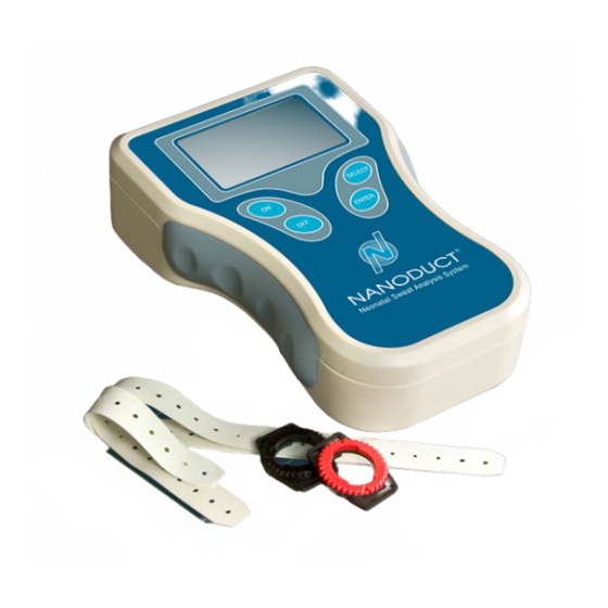
- Page 1 NANODUCT® Neonatal Sweat Analysis System MODEL 1030 USER’S MANUAL...
- Page 3 NANODUCT® NEONATAL SWEAT ANALYSIS SYSTEM MODEL 1030 USER’S MANUAL 57-0008-02A (Last update 7/8/2020)
- Page 4 © 2020 ELITechGroup Inc. All rights reserved. Printed in the United States of America. No part of this publication may be reproduced, transmitted, transcribed, stored in a retrieval system, or translated into any language (human or computer) in any form, or by any means whatsoever, without the prior express written permission of ELITechGroup Inc.
-
Page 5: Table Of Contents
Table of Contents Section 1: Introduction 1.1 Overview 1.2 Customer Service 1.3 System Description Holders Iontophoretic Electrodes Electrode Cable Assembly Pilogel Iontophoretic Discs Sensor Cell Induction/Analysis Module 1.4 Controls and Connections Display Serial Data Ports Section 2: Initial System Setup 2.1 Installing or Replacing the Batteries 2.2 Menu Basics Startup Menu... - Page 6 Appendix H: Supplemental Information Cystic Fibrosis: A Brief Description of the Disease The Evolution of Sweat Test Methods Development of the Nanoduct Neonatal Sweat Collection System References Appendix I: Pilocarpine Iontophoresis: Requirements and Risks Burns Under Iontophoresis Appendix J: Electromagnetic Compatibility (EMC) Index...
-
Page 7: Section 1: Introduction
Section 1: Introduction 1.1 Overview This manual describes the complete procedure for the laboratory diagnosis of cystic fibrosis, particularly in the early neonatal period, through examination of sweat electrolyte concentration using measurement of electrical conductivity. The first section gives a brief description of the system, its components, and how to set up the system. - Page 8 Section 1: Introduction Statement of Environmental Limits This equipment is designed to be safely operated at 15 to 30 °C, with maximum relative humidity less than 85%, and atmospheric pressure ≥ 79.5 kPa. Understanding Warnings This manual uses three warning levels to alert the operator to important information as shown in the following examples.
- Page 9 Section 1: Introduction WARNING! Consult a physician before performing a test on patients who have had previous adverse reactions to electrotherapy. WARNING! The lithium coin cell backup battery used to power the clock is not accessible to the user and should only be replaced by qualified service personnel.
- Page 10 Section 1: Introduction Contraindications • Patients with an implanted device, such as a defibrillator, neurostimulator, pacemaker, or ECG monitor. • Patients with a history of epilepsy or seizures. • Patients who are pregnant. • Patients that have a known sensitivity or allergy to any ingredient. •...
- Page 11 Section 1: Introduction EXPLANATION OF SYMBOLS SYMBOL EXPLANATION Classification of degree of protection against electric shock (BF) Authorized Representative in the European Community Batch Code Biological Hazards (Biological Risks) Catalog Number (Model Number) Serial Number Consult Instructions For Use General Warning, Caution, Risk of Danger Caution, Consult Accompanying Documents (Attention, see instructions for use) CE Mark, product meets the essential requirements...
- Page 12 Section 1: Introduction SYMBOL EXPLANATION Use By Temperature Limitation – indicates high and low limits Warning, Biological Hazard Harmful / Irritant Environment Hazard Toxic...
-
Page 13: Customer Service
Section 1: Introduction 1.2 Customer Service ELITechGroup is dedicated to assisting in every aspect of sweat testing theory and practice. ELITechGroup is the acknowledged world leader in the development of innovative systems for cystic fibrosis diagnosis by sweat testing. This manual contains basic maintenance, troubleshooting, and service information. ELITechGroup is prepared to help you resolve any difficulty with the operation or performance of your Nanoduct Neonatal Sweat Analysis System. -
Page 14: System Description
Section 1: Introduction 1.3 System Description Nanoduct is a complete, integrated system for inducing and analyzing sweat for cystic fibrosis (CF) diagnosis—all while attached to the patient. This reduces the possibility of intrinsic error and enables pristine samples to be obtained from neonates and analyzed in situ. -
Page 15: Pilogel Iontophoretic Discs
Section 1: Introduction Pilogel Iontophoretic Discs Pilogel discs are small (surface area 2.5 cm ) iontophoretic discs that are inserted into the electrode assemblies before iontophoresis. Designed especially for neonates, these discs have a pilocarpine concentration of 1.5% for optimum stimulation of the sweat gland, which also reduces the iontophoresis time to approximately 2.5 minutes. -
Page 16: Induction/Analysis Module
Section 1: Introduction Induction/Analysis Module The battery-operated electronic induction/analysis module controls the Nanoduct system. The module performs six separate functions: 1. Provides a timed and controlled current for iontophoretic sweat stimulation. 2. Measures electrical conductivity of the excreted sweat during the analysis phase. -
Page 17: Controls And Connections
Section 1: Introduction 1.4 Controls and Connections Electrode Socket The electrode socket on the top of the enclosure connects the electrode/sensor cable assembly to provide electrical current for sweat stimulation and to receive sensor signals to the induction/analysis module during the analysis phase. Keypad Keys The ON key turns the instrument on when pressed. -
Page 18: Serial Data Ports
Section 1: Introduction Serial Data Ports RS-232 Port The Nanoduct RS-232 port uses a DB9 connector located on the top of the instrument. This port is for asynchronous serial communication with a printer or computer. The RS-232 port can be used to print out results of sweat tests (with a time and date stamp). - Page 19 Section 1: Introduction Model/Serial Number Identification Label The following label is located on the back of the instrument.
- Page 20 Section 1: Introduction User Interface Block Diagram...
-
Page 21: Section 2: Initial System Setup
Section 2: Initial System Setup 2.1 Installing or Replacing the Batteries 1. The battery compartment is on the back of the instrument. Turn the instrument so that the back is facing up. Using a Phillips screwdriver, remove the two screws that are holding the battery door in place. Remove the battery door. -
Page 22: Menu Basics
The sign-on ELITechGroup screen includes ELITechGroup’s name, the Nanoduct product name, the software NANODUCT 1030 part number, the release date, and the display language. The Nanoduct then performs a system check with a “Checking Operation” message displaying briefly. -
Page 23: Using The Configure Menu
Section 2 : Initial System Setup Using the Configure Menu Use the Configure Menu to set the clock, display language, for suppressing or displaying test results, and forcing a Calibration Check when the instrument is SETUP MENU turned on. 2019-03-24 12:04 1. Select “Configure” from the SETUP MENU and press ENTER. Exit Configure Self Test... - Page 24 Section 2 : Initial System Setup 3. With the minutes digits flashing, press SELECT to adjust the minutes. Pressing the SELECT key increments the minutes one minute at a time. Set Minutes After reaching 59, the minute returns to 00. 16:07 With the desired minutes displayed, press ENTER to set the minutes.
-
Page 25: Setting Options
Section 2 : Initial System Setup Setting Options 1. From the CONFIGURE MENU, select “Set Options” and press ENTER. CONFIGURE MENU Exit Set Clock Set Options Set Language 2. To display or suppress the results of the sweat test, select either “Suppress Readings”... -
Page 26: Setting Language
Section 2 : Initial System Setup Setting Language 1. The display language is set from the CONFIGURE MENU. Select “Set Language” and press ENTER. Language selections include English, CONFIGURE MENU French, German, and Spanish. Exit Set Clock Set Options Set Language 2. - Page 27 Section 2 : Initial System Setup 3. Connect the electrodes by placing a Pilogel disc in each holder and then holding the two discs together between two fingers to check the current. The current should read approximately 0.5 mA. The instrument continues to Self Test Mode read and display the electrode current reading.
-
Page 28: Demo Mode
Section 2 : Initial System Setup Demo Mode The Demo Mode is used to simulate typical displays that are seen during normal operation. This can be useful for demonstrating instrument function or to SETUP MENU familiarize the user with the instrument. No actual iontophoresis or sweat analysis 2019-01-31 12:03 occurs in this mode and only simulated results display. - Page 29 Section 2 : Initial System Setup The following is a sequence of displays when working in Demo Mode. From the Demo Mode main menu, select Iontophoresis and press ENTER. To advance to the next screen, press ENTER or wait for the test to complete.
-
Page 30: Section 3: Sweat Induction And Analysis
With medical approval, remove the patient from that environment during iontophoresis. 1 Assemble Equipment and Supplies Make certain everything is on hand for the complete procedure: • Nanoduct 1030 • Two holders • Two holder straps with strap retainer posts • Two Pilogel discs •... - Page 31 Section 3: Sweat Induction and Analysis 4 Clean Selected Skin Areas Select the anodic (positive) skin site for the greatest density of sweat glands. The site must be well-removed from the wrist where movement of tendons or ligaments could possibly affect the stability of the attached units. In neonates, the optimum site is the flexor aspect of the forearm, approximately halfway between wrist and elbow.
- Page 32 Section 3: Sweat Induction and Analysis E. Draw the skin back around the holder to remove any underlying wrinkles. F. Position the negative (black) holder (on the same limb) in the same manner. 6 Insert Pilogels Into the Iontophoretic Electrodes Insert a gel into each electrode assembly.
- Page 33 Section 3: Sweat Induction and Analysis C. Once current has reached the full 0.5 mA, that level is maintained for 2 minutes. The display shows “Full Current” and a time bar at the bottom of Iontophoresis the screen shows progress. Full Current D.
- Page 34 Section 3: Sweat Induction and Analysis 11 Insert Sensor Into Positive Holder Insert the sensor (without being attached to the wiring harness) into the holder (red locking ring) as described in steps 7a and 7b, taking care not to disturb the holder or touch the bottom of the sensor.
- Page 35 Section 3: Sweat Induction and Analysis 14 Record the Result A. With the sensor and black electrode in place, the display indicates sweat contact with the first electrode within a few minutes. Sweat Analysis After another 2 to 6 minutes (all timing is approximate, depending on the Electrolyte initial sweat rate of the patient) the conductivity display should begin to Concentration...
- Page 36 Section 3: Sweat Induction and Analysis 15 Remove Holders and Sensor, and Clean Electrodes A. Disconnect the cable from the sensor. Remove the sensor from the holder and discard the used sensor. Immediately and properly dispose of the Pilogel disc from the negative (black) electrode. WARNING! Due to possible biological contamination, Nanoduct sensors are single use only and must be discarded after use.
-
Page 37: Interpreting The Sweat Test
Section 3: Sweat Induction and Analysis 3.2 Interpreting the Sweat Test Units of Conductivity Electrical conductivity–essentially an electrical measurement–should properly be measured in siemens/cm. However, we use conductivity to indirectly measure electrolyte concentration. Since medical professionals are more familiar with standard chemical units (such as mmol/L) for concentration, the siemens/cm units have not been used for conductivity values in the practice of clinical chemistry, to prevent confusion. -
Page 38: Diagnostic Ranges
Section 3: Sweat Induction and Analysis The induction/analysis module is therefore programmed to make an average conductivity assessment by noting the time at which the first conductivity result is displayed, allowing a time lapse of 3 minutes and then commencing a 5-minute averaging period, after which the mean value is displayed. Diagnostic Ranges Using the data displayed in Fig 1, which show both sweat rate and conductivity variation with time after stimulation, the Nanoduct averaged value (over period C) -
Page 39: Notes Regarding Sweat Rate
1 g/m /min is not achieved. To provide the most information for subsequent consideration, the Nanoduct 1030 will display an initial sweat rate reading even if it is below 1 g/m... -
Page 40: Section 4: Troubleshooting And Preventive Maintenance
Section 4: Troubleshooting and Preventive Maintenance 4.1 Troubleshooting General Troubleshooting and Diagnosis Symptom Probable Causes / Possible Solutions Nothing happens when the On button Probable Causes: is pressed, display remains blank, or Low or dead batteries. is not responsive when buttons are pressed. - Page 41 Section 4: Troubleshooting and Preventive Maintenance Symptom Probable Causes / Possible Solutions Insufficient sweat rate or insufficient Probable Causes: sweat for Sweat Analysis to Insufficient sweat may occur for a variety of reasons and varies complete. depending upon patient. Physiological factors, such as the patient’s (See also Error Message age, weight, race, and hydration level may contribute to insufficient Troubleshooting below.)
- Page 42 Section 4: Troubleshooting and Preventive Maintenance Symptom Probable Causes / Possible Solutions Communication problems or incorrect Probable Causes: information sent to Nanoduct Lab Communication settings are not correct. Report or printer. Damaged communication cable. Nanoduct hardware or software problem. Possible Solutions: Check RS-232 communication settings on the computer or printer.
-
Page 43: Error Message Troubleshooting And Diagnosis
Section 4: Troubleshooting and Preventive Maintenance Error Message Troubleshooting and Diagnosis Error Message Screen Probable Causes / Possible Solutions Displayed Low Battery Main Menu Probable Causes: Battery voltage is below the low battery threshold. Possible Solutions: Replace all four batteries. After replacing the batteries, if the same problem persists, contact ELITechGroup for further instructions. - Page 44 Section 4: Troubleshooting and Preventive Maintenance Error Message Screen Probable Causes / Possible Solutions Displayed Open Loop Iontophoresis Probable Causes: Fault No Pilogel discs under electrodes. Check Electrodes Dirty electrodes. Electrodes not properly latched with locking ring or cable not connected to Nanoduct. Holders not adequately secured to patient.
- Page 45 Section 4: Troubleshooting and Preventive Maintenance Error Message Screen Probable Causes / Possible Solutions Displayed High Resistance Iontophoresis Probable Causes: Fault No Pilogel discs under electrodes. Moisten Skin Dirty electrodes. Electrodes not properly latched with locking ring or cable becoming detached from Nanoduct. Holders not adequately secured to patient.
- Page 46 Section 4: Troubleshooting and Preventive Maintenance Error Message Screen Probable Causes / Possible Solutions Displayed Initial Sweat Rate Sweat Analysis Probable Causes: Not Valid Black electrode removed during sweat analysis. Recall Reading Red sensor connector not connected to the sensor cell before sweat flows into sensor cell.
- Page 47 Section 4: Troubleshooting and Preventive Maintenance Error Message Screen Probable Causes / Possible Solutions Displayed Fault Sweat Analysis Probable Causes: Sweat Analysis Was Insufficient sweat collected for analysis due to sensor Not Completed cell not properly latched with locking ring or holder not Recall Reading adequately secured to patient.
- Page 48 Section 4: Troubleshooting and Preventive Maintenance Error Message Screen Probable Causes / Possible Solutions Displayed Fault Sweat Analysis Probable Causes: Sweat Analysis Was Insufficient sweat collected for analysis or air bubbles Not Valid present in sensor cell due to sensor cell not properly Recall Reading latched with locking ring or holder not adequately secured to patient.
-
Page 49: Cleaning The Instrument
Section 4: Troubleshooting and Preventive Maintenance 4.2 Cleaning the Instrument When needed, the induction/analysis module surfaces and accessories should be wiped down using a soft cloth dampened with mild detergent or 10% household bleach solution. Electrodes must be cleaned following each iontophoresis procedure as follows: 1. -
Page 50: Calibration And Checking Control Values
Section 4: Troubleshooting and Preventive Maintenance 4.3 Calibration and Checking Control Values Patient Simulator ELITechGroup offers the AC-111 Patient Simulator as an accessory to the Nanoduct for those who wish to measure unknown samples as part of a proficiency study or to verify or validate the function and accuracy of the Nanoduct instrument. - Page 51 Section 4: Troubleshooting and Preventive Maintenance 6. The Nanoduct calibrates to the 80 mmol/L (equivalent NaCl). The screen indicates that the instrument is calibrating and to please wait. When the Calibrating calibration has been completed, the screen advances to the next screen. Please Wait.
-
Page 52: Appendix A: Instrument Specifications
Appendix A: Instrument Specifications Instrument Specifications Readout 128 x 64 LCD graphic display (non-backlit). Supports up to 8 lines of 18 characters or numerals, with multi-lingual support (English, French, German, and Spanish). Sound Alert signals. Keyboard ON, OFF, SELECT and ENTER keys. Electrode Connection 6-pin locking medical connector to mate with induction/conductivity cell, cable. - Page 53 Appendix A: Instrument Specifications Instrument Specifications Transport Temperature 0 to 60 °C (32 to 140 °F). Transport Relative Humidity ≤ 85%, non-condensing. Instrument (H x W x D) 7.5 x 5 x 2 in (19.1 x 12.7 x 5.1 cm). Weight 1.2 lb (0.5 kg).
-
Page 54: Appendix B: Accessories, Supplies, And Replacement Parts
Positive Red Electrode and Sensor Cell Holder RP-358 Negative Black Electrode Holder RP-354 Holder Attachment Strap, Small, 1 each RP-355 Holder Attachment Strap, Medium, 1 each RP-356 Holder Attachment Strap, Large, 1 each RP-238 Clock Battery, 1 each RP-444 Nanoduct 1030 User’s Manual... -
Page 55: Appendix C: Serial Data Ports
Appendix C: Serial Data Ports RS-232 Serial Port WARNING! Do not connect a line powered printer or computer when the instrument is attached to a patient. The Nanoduct RS-232 port uses a DB9 connector located on the top of the instrument. This port is for serial communication with a printer. -
Page 56: Appendix D: Critical Components
Appendix D: Critical Components Pilogel Discs for Nanoduct (part of SS-043 Supply Kit for NANODUCT) Product(s) Critical Components Pilogel Discs for Pilocarpine Nitrate= 1.4 % (USP grade) Nanoduct contain: Methyl Paraben (Methyl p-Hydroxybenzoate) [preservative] = 0.06% Propyl Paraben (Propyl p-Hydroxybenzoate) [preservative] = 0.03% SS-043 Supply Kit for NANODUCT Hazard Pictogram Signal word... -
Page 57: Appendix E: Pilogel Information
1 in 50,000 tests, based on current data and reported events, there have been no reported burns using Pilogel Discs for Nanoduct and the original Nanoduct system or the Nanoduct 1030. Burn descriptions vary from “tiny black pinholes in the skin” to “crater-like, third degree burns two to three millimeters in diameter.”... - Page 58 Appendix E: Pilogel Information Reference Numbers: SS-043 Supply Kit for Nanoduct with 32-0100 Pilogel Discs for Nanoduct ® ® Name and Business Address of Manufacturer: ELITechGroup Inc. 370 West 1700 South Logan, Utah 84321-8212...
-
Page 59: Appendix F: Storage And Handling Conditions
Appendix F: Storage and Handling Conditions Storing the Instrument Before storing the Nanoduct do the following: Wipe down the induction/analysis module surfaces and accessories using a soft cloth dampened with mild detergent or 10% household bleach solution. Electrodes must be cleaned as follows: 1. -
Page 60: Appendix G: Shipping And/Or Disposal Instructions
Appendix G: Shipping and/or Disposal Instructions Shipping the Nanoduct Instruments must be cleaned before returning them to an authorized service center. A charge is assessed if an instrument must be cleaned or decontaminated at the service center. WARNING! During decontamination, use universal precautions: eye protection, gloves, lab coat, and ventilation. - Page 61 Appendix H: Supplemental Information Cystic Fibrosis: A Brief Description of the Disease Cystic fibrosis of the pancreas (or mucoviscidosis) is due to one of the many known ‘inborn errors of metabolism’ that are fundamentally the result of aberrations in the structure of the genetic material. It is classed as lethal because of the very poor prognosis afforded to sufferers.
- Page 62 Appendix H: Supplemental Information While the iontophoretic transport of pilocarpine into the glands has remained the universally preferred method of sweat stimulation to this day, the need for a simpler method of collection and analysis spawned the development of alternative procedures during the late 60’s and early 70’s. Principally among these were the cup-collection systems, which used electrical conductivity for analysis, and the direct skin chloride electrode system.
- Page 63 Appendix H: Supplemental Information Development of the Nanoduct Neonatal Sweat Collection System During almost twenty years of successful deployment of the Macroduct Sweat-Chek System it began to be realized that a truly neonatal sweat test was needed, one that preserved the error-free anaerobic handling of the sweat sample employed in Macroduct, yet at the same time was particularly designed to meet the special requirements of the newborn infant during the first two weeks of life.
- Page 64 Appendix H: Supplemental Information References 1) Gibson, L. E., Cooke, R. E., A test for concentration of electrolytes in sweat in cystic fibrosis of the pancreas utilizing pilocarpine iontophoresis. Pediatrics 1959; 23: 545-9. 2) Gibson, L. E., The Decline of the Sweat Test. Comments on Pitfalls and Reliability.
- Page 65 50,000 tests, based on current data and reported events, there have been no reported burns using the original Nanoduct system or the Nanoduct 1030.The low rate is due to ELITechGroup’s insistence on proper test procedures together with built-in equipment safety provisions that minimize the risk of even mild...
- Page 66 Appendix J: Electromagnetic Compatibility (EMC) Medical Electrical Equipment, in general, needs special precautions regarding EMC and needs to be used according to the EMC information provided in the accompanying documents. Portable and mobile RF communications equipment can affect Medical Electrical Equipment. The Nanoduct instrument is not susceptible to some types of electrical interference, because it is battery- powered and doesn’t connect to power lines that might conduct high frequency noise along with the power.
- Page 67 Appendix J: Electromagnetic Compatibility (EMC) Guidance and Manufacturer’s Declaration – Electromagnetic Immunity The Nanoduct system is intended for use in the electromagnetic environment specified below. The customer or the operator of the Nanoduct system should assure that it is used in such an environment. IEC 60601-1-2 Test Level Compliance Level Immunity...
- Page 68 Appendix J: Electromagnetic Compatibility (EMC) Recommended separation distances between portable and mobile RF communications equipment and the Nanoduct System The Nanoduct is intended for use in an electromagnetic environment in which radiated RF disturbances are controlled. The customer or the operator of the Nanoduct can help prevent electromagnetic interference by maintaining a minimum distance between portable and mobile RF communications equipment (transmitters) and the Nanoduct as recommended below, according to the maximum output power of the communications equipment.
- Page 69 Index Self Test Mode 26 Fault Condition 40 Sensor 34, 36 Fiber Pilocarpine Reservoirs 14, 15, 32, 56, 57 cable 14, 30, 32 Cell 15 Accessories 54 connector 17 Alkali Accumulation (during ionto- Serial Data Ports 18, 55 Glycerol 15 phoresis) 15 Setup Menu 22 Anodic acidification 15...
- Page 71 57-0008-02A ELITechGroup Inc. 370 West 1700 South Logan Utah 84321-8212 800 435 2725 www.elitechgroup.com +1 435 752 6011 info@elitechgroup.com...
Need help?
Do you have a question about the NANODUCT 1030 and is the answer not in the manual?
Questions and answers