Table of Contents
Advertisement
Quick Links
Advertisement
Table of Contents

Related Manuals for Mandik FDMA PM


Summary of Contents for Mandik FDMA PM
-
Page 2: Table Of Contents
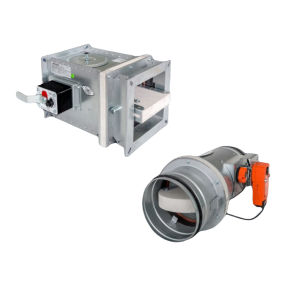
These technical specifications state a row of manufactured sizes and models of fire dampers (further only dampers) FDMA PM. It is valid for production, designing, ordering, delivery, assembly and operation. 1. Description......................... 2. Design..........................3. Communication and control devices………................. 4. Dimensions, weights and effective area................ - Page 3 Round dampers have one inspection hole, since the shutting device and the inspection hole can be set into the most advantageous position (with respect to the operation and manipulation with the control device). Dampers FDMA PM are variant of FDMA dampers with blade control out of axis.
- Page 4 Damper characteristics • CE certified acc. to EN 15650 • Tested in accordance with EN 1366-2 • Classified acc. to EN 13501-3+A1 • Fire resistance EIS 120, EIS 90 • External Casing leakage class C, Internal leakage class 2 acc. to EN 1751 •...
- Page 5 Design .01 with mechanical control can be complemented with a limit switch signalling of the damper blade position "CLOSED". Cable is connected directly to limit switch. Limit switch Limit switch “CLOSED” “CLOSED” Design .01 with mechanical control can be complemented with a terminal switches signaling of the damper blade position "CLOSED"...
- Page 6 1(COM) - black wire 2(NC) - gray wire 4(NO) - blue wire AC 230V / 5A This limit switch is possible to connect in following two versions: IP 67 if the arm is moving … connect wire 1+2 -25°C … +120°C if the arm is moving …...
- Page 7 Design with actuating mechanism FDMA PM is always equipped by electric actuating mechanism BFL, BFN, BF 230-TN or BFL, BFN, BF 230-TN (further only "actuating mechanism"). After being connected to power supply AC/DC 24V or 230V, the actuating mechanism displaces the damper blade into operation position "OPEN"...
- Page 8 S1 S2 <5° <80° Nominal voltage AC 24 V 50/60 Hz AC 230 V 50/60 Hz DC 24 V Power consumption - motoring 3,5/5 W 2,5/4 W - holding 1,1/2,1 W 0,8/1,4 W Dimensioning 6,5/10 VA (Imax 4 A @ 5 ms) 4/6 VA (Imax 8,3 A @ 5 ms) Protection class Degree of protection...
- Page 9 Nominal voltage AC 24 V 50/60 Hz AC 230 V 50/60 Hz DC 24 V Power consumption - motoring - holding Dimensioning 10 VA (Imax 8,3 A @ 5 ms) 12,5 VA (Imax 500 mA @ 5 ms) Protection class Degree of protection IP 54 Running time - motor...
- Page 10 RS-Bus communication relay contact relay contact 24 V DC...
- Page 11 Design with the communication and supply device BKN 230-24 and the actuating mechanism BF 24-TN-ST (BFL 24-T, BFN 24-T). It simplifies electrical wiring and interconnection of fire flap valves. It facilitates on site check and enables central control and checks of fire damper by means of a simple 2-conductor wiring.
- Page 12 Bridge has been installed by the manufacturer. If needed, it can be removed ad replaced with a thermoelectric starting mechanism. If terminals 1 and 2 are not interconnected, safety function is initiated. Bridge can be used only for starting and without BKS24… ! Two conductor wiring to BKS24 Design .61 with communication and supply device can be complemented with smoke detector ORS 142 K.
- Page 13 Design .60 with communication and supply device can be complemented with smoke detector ORS 142 K. For supply and comunnication is used BKN 230-24-MOD, which is used together with the BF 24TN-ST (BFL 24T-ST, BFN 24T-ST) for communication with control systems using the Modbus RTU or BACnet MS / TP protocol.
- Page 14 External smoke detector, +24 V, max. 50 mA External smoke detector, control input BKN Direct Control, override control input Design with the communication and supply device BKN 230-24MP and actuating mechanism BF 24TL-TN-ST for connection to MP-Bus. BKN 230-24MP supplies to intelligent actuating mechanisms of fire dampers BF 24TL-TN-ST decentrally needed power supply.
- Page 15 Actuating mechanism Actuating mechanism Nominal voltage AC 24 V 50/60Hz DC 24 V Power consumption - motoring - holding Dimensioning 10 VA (Imax 8,3 A @ 5 ms) Protection class Degree of protection IP 54 Running time - motor 120 sec - spring return ~ 16 sec Ambient temperature...
- Page 16 additional external conntact, net MP-Bus eg. fire smoke detector PC Tool AC230 V Nominal voltage AC 230 V 50/60Hz Power consumption 14 W (including actuating mechanism) Dimensioning 16 VA (including actuating mechanism) Protection Class Degree of protection IP 40 Ambient temperature -30°C …...
-
Page 17: Description
BKS 24-1B communication and control device is used for control and checks of fire dampers with the BF 24-TN-ST (BFL 24-T-ST, BFN 24-T-ST) actuating mechanism in conjunction with the BKN 230-24 supply and communication device. BKS 24-1B receives information about the situation of the fire damper through the BKN 230-24 supply and communication device and issues controlling commands. - Page 18 Nominal voltage AC 24 V 50/60Hz Power consumption 2,5 W (operating position) Dimensioning 5 VA Protection Class Degree of protection IP 30 Ambient temperature 0 … +50°C 11-pole connector ZSO-11, it is not part of BKS24-1B, Connection ZSO-11 is 11-pole screw terminal 11 x 1,5 mm² BKS 24-9A communication and control device is used for group control and checks of 1 to 9 fire dampers with the actuating mechanism BF 24-TN-ST (BFL 24-T-ST, BFN 24-T-ST) in connection with the supply and communication device BKN 230-24.
- Page 19 Nominal voltage AC 24 V 50/60Hz Power consumption 3,5 W Dimensioning 5,5 VA Protection Class Degree of protection IP 30 Ambient temperature 0 … +50°C Connection terminal 2 x 1,5 mm²...
- Page 20 Rectangular dampers B - 10 Damper casing Mechanics Damper blade Inspection hole covering Sensor sticker Hole for camera B - 10 Damper casing Actuating mechanism Damper blade Inspection hole covering BAT thermoelectrical starting mechanism Hole for camera...
- Page 21 Round dampers Damper casing Mechanics Damper blade Inspection hole covering Sensor sticker Hole for camera Damper casing Actuating mechanism Damper blade Inspection hole covering BAT thermoelectrical starting mechanism Hole for camera...
-
Page 22: Dimensions, Weights And Effective Area
Rectangular dampers - dimensions, weights and effective area 10,5 0,0178 19,0 20,5 0,1070 11,0 0,0209 19,5 21,0 0,1130 10,0 11,5 0,0248 20,0 21,5 0,1170 10,5 12,0 0,0287 21,0 22,5 0,1270 11,0 12,5 0,0333 21,0 22,5 0,1290 11,5 13,0 0,0364 22,0 23,5 0,1370 80,5... - Page 23 80,5 14,5 16,5 0,0688 13,5 15,5 0,0431 100,5 15,5 17,5 0,0798 14,0 15,5 0,0506 17,0 18,5 0,0921 14,5 16,5 0,0600 18,0 21,0 0,1059 15,0 17,0 0,0694 19,5 22,5 0,1196 16,0 18,0 0,0806 20,5 23,5 0,1334 16,5 18,0 0,0881 21,0 24,0 0,1361 80,5 17,0...
- Page 24 29,5 32,5 0,2684 24,5 27,5 0,1926 30,0 33,0 0,2779 26,5 29,5 0,2214 32,0 35,0 0,3016 28,5 31,5 0,2501 32,0 35,0 0,3064 30,0 33,0 0,2789 33,5 36,5 0,3254 30,5 33,5 0,2846 35,0 38,0 0,3491 32,0 35,0 0,3076 16,5 18,0 0,0604 33,0 36,0 0,3249 17,0...
- Page 25 22,0 23,5 0,1080 41,5 44,5 0,4604 23,0 24,5 0,1249 41,5 44,5 0,4676 24,5 26,0 0,1451 43,0 46,0 0,4966 25,5 27,0 0,1586 45,0 48,0 0,5329 80,5 26,0 27,5 0,1688 22,0 23,5 0,0891 100,5 27,5 29,0 0,1958 23,0 24,5 0,1046 29,5 31,0 0,2261 23,5 25,5...
- Page 26 40,0 43,0 0,4241 56,5 59,5 0,7166 42,5 45,5 0,4729 60,0 63,0 0,7779 43,0 46,0 0,4826 60,0 63,0 0,7901 45,0 48,0 0,5216 62,5 65,5 0,8391 47,0 50,0 0,5509 65,5 68,5 0,9004 48,0 51,0 0,5704 34,0 35,5 0,1581 51,0 54,0 0,6191 35,5 37,0 0,1856 51,0...
- Page 27 Round dampers - dimensions, weights and effective area 0,0137 0,0182 0,0248 10,3 0,0323 16,5 11,2 0,0427 34,0 10,6 12,2 0,0565 54,0 12,6 14,2 0,0747 76,5 13,7 16,7 0,0982 101,5 15,6 18,6 0,1279 126,5 18,5 21,5 0,1617 156,5 21,3 24,3 0,2073 191,5 24,5 27,5...
- Page 28 Blades overlaps Act. mechanism side "a" Tab. 4.3.1 Side without act. mechanism "c" Tab. 4.3.1 Act. mechanism side "e" Tab. 4.4.1 Side without act. mechanism "f" Tab. 4.4.1 Act. mechanism side "g" Tab. 4.4.2 Side without act. mechanism "h" Tab. 4.4.2 For the design .60 (with BKN supply and communication device) add to weight of the damper with an actuating mechanism (from the Tab.
- Page 29 Fire dampers are suitable for installation in arbitrary position in vertical and horizontal passages of fire separating constructions. Damper assembly procedures must be done so as all load transfer from the fire separating constructions to the damper body is absolutely excluded. Back-to-back air-conditioning piping must be hung or supported so as all load transfer from the back-to-back piping to the damper is absolutely excluded.
- Page 30 Built in edge Built in edge "Wall edge sticker" indicates the recommended edge of installation of fire damper into the fire partition structure (wall). The damper must be installed so that the entire damper blade - in the closed position - is located inside the fire separating structure (wall) and at the same time the control mechanism and inspection openings are freely accessible.
- Page 31 For dampers with flanges is valid D + 160 mm ** The recommended dimension of the installation opening is from 40 mm to 80 mm on the both sides (it means from D+80 to D+160) Examples of fire damper installing The fire damper can be integrated into a solid wall construction made e.g.
- Page 32 Statement of installations the fire dampers FDMA PM EIS 120 Mortar or gypsum EIS 90 Stuffing box + mastic and cement lime plate EIS 90 Battery - Mortar or gypsum EIS 90 Installation frame E1, E2, E4, R1, R2, R3, R4, R5...
- Page 33 ≥ 100 ≥ 50* * Around the perimeter ≥ 100 ≥ 40 POSITION: Fire damper FDMA PM Solid wall construction Mortar or gypsum Duct...
- Page 34 ≥ 67 ≥ 10 ≥ 50 ≥ 40 Fire damper FDMA PM-C - installation opening for each damper has minimal dimensions ● a x b = (A+100) x (2xB +100) mm or (2xA+100) x (B +100) mm POSITION: Fire damper FDMA PM-K - installation opening for each damper has minimal dimensions ●...
- Page 35 POSITION: Wool is fixed to damper body and construction by fire ● protection mastic. Fire damper FDMA PM Mineral wool thickness = construction thickness + 20 mm ● Mortar or gypsum or 50 mm Mineral stone wool min. density 140 kg/m ●...
- Page 36 ● Fire damper FDMA PM construction must be filled by glue (PROMAT K84). Wool is fixed to installation frame and construction by fire Fire damper FDMA PM with installation frame R1, R2 ● protection mastic. Mortar or gypsum Installation is valid for ceiling construction ●...
- Page 37 D ≤ 400 400 < D ≤ 800 800 < D ≤ 1000 POSITION: Fire damper FDMA PM with installation frame R3, R4 Fire damper FDMA PM with installation frame R5 ● Wool is fixed to installation frame and construction by fire Mineral stone wool min.
- Page 38 ≥ 50 ≥ 40 Used materials - example**: POSITION: Promapyr, Rockwool Steprock HD Fire damper FDMA PM Promastop - P, K Solid wall construction Promatect - H Mineral stone wool min. density 140 kg/m Fire protection mastic min. thickness 1 mm Fire resistant insulation and fire resistant board can Cement lime plate min.
- Page 39 ≥ 100 ≥ 100 ≥ 100 ≥ 100 ≥ 100 ≥ 100 POSITION: Fire damper FDMA PM Installation frame Solid wall construction Installation details see chapter 7...
- Page 40 A+60 to 800 max. 1650 ≥ 100 D+60 to 800 max. 2050 POSITION: 1 Fire damper FDMA PM D+60 to 800 2 Solid wall construction max. 1650 3 Fire resistant board 4 Fire stop coating thickness 1 mm ≥ 100...
- Page 41 Solid wall construction must be filled by glue (PROMAT K84) 2800 < A1 ≤ 3000 ● Fire damper FDMA PM-C - distance between dampers 104 mm Mineral stone wool min. Fire damper FDMA PM-K - distance between dampers 160 mm ●...
- Page 42 ≤ 300 Screws has to be fixed in wall/ceiling con- struction. (If it is needed use steel bracket). ≥ 50 ≥ 40 POSITION: Fire damper FDMA PM variable*** ≥ 400 ≥ 100 Solid wall construction ≥ 100 Stuffing box (mineral stone wool min. density 140 kg/m ) Screw ≤...
- Page 43 ≥ 50* * Around the perimeter ≥ 100 ≥ 50 ≥ 100 POSITION: Fire damper FDMA PM Installation frame Solid wall construction Cement lime plate Duct Installation details see chapter 7...
- Page 44 150* ≥ 50** * min. 110 - Concrete/ min. 125 - Aerated concrete ** Around the perimeter 150* ≥ 40 POSITION: Fire damper FDMA PM Solid ceiling construction Mortar or gypsum Duct...
- Page 45 * min. 110 - Concrete/ min. 125 - Aerated concrete ** Around the perimeter ● Fire damper FDMA PM-C - installation opening for each damper has minimal dimensions a x b = (A+100) x (2xB +100) mm or (2xA+100) x (B +100) mm POSITION: Fire damper FDMA PM-K - installation opening for each damper has minimal dimensions ●...
- Page 46 ≥ 40 150* Used materials - example**: POSITION: Promapyr, Rockwool Steprock HD Fire damper FDMA PM Promastop - P, K Solid ceiling construction Promatect - H Mineral stone wool min. density 140 kg/m Fire protection mastic min. thickness 1 mm Fire resistant insulation and fire resistant board can Cement lime plate min.
- Page 47 150* 150* 150* 150* 150* 150* * min. 110 - Concrete/ min. 125 - Aerated concrete POSITION: Fire damper FDMA PM Installation frame Solid ceiling construction Installation details see chapter 7...
- Page 48 2050 max. 1650 150* * min. 110 - Concrete/ min. 125 - Aerated concrete POSITION: 1 Fire damper FDMA PM 2 Solid ceiling construction 3 Fire resistant board 4 Fire stop coating thickness 1 mm 5 Duct Fire resistant insulation and fire resistant board can be...
- Page 49 2 Solid ceiling construction must be filled by glue (PROMAT K84) 2800 < A1 ≤ 3000 ● Fire damper FDMA PM-C - distance between dampers 104 mm 3 Stuffing box (mineral stone ● Fire damper FDMA PM-K - distance between dampers 160 mm wool min.
- Page 50 ≥ 100 ≥ 150 variable**** ≥ 400 POSITION: Fire damper FDMA PM Solid ceiling construction Mortar or gypsum Stone wool bound with use of an organic resin with crushed stone as a refrigerant (min. density 300 kg/m ), EIS 90, thickness 60 mm Stone wool with one side stitched wire fencing (min.
- Page 51 ≤ 750 ≤ 750 150** 150* POSITION: Fire damper FDMA PM Solid ceiling construction ≤ 100 Concrete B20 Rebar * min. 110 - Concrete/ min. 125 - Aerated concrete ** Around the perimeter Duct ≤ 750 ≤ 750 150* 150*...
- Page 52 ≥ 50** 150* * min. 110 - Concrete/ min. 125 - Aerated concrete ** Around the perimeter ≥ 50 150* POSITION: Fire damper FDMA PM Installation frame Solid ceiling construction Cement lime plate Duct Installation details see chapter 7...
- Page 53 (UW, CW). Profil is fixed by screws ≥3,5 mm with corresponding length. Distance between screws ≤200 mm. ≥ 40 POSITION: Fire damper FDMA PM Gypsum plate Mineral wool (type depending on the type of construction) Mortar or gypsum Duct...
- Page 54 ≥ 50 ≥ 40 ● Fire damper FDMA PM-C - installation opening for each damper has minimal dimensions POSITION: Dimensions = (A+100) x (2xB +100) mm or (2xA+100) x (B +100) Fire damper FDMA PM-K - installation opening for each damper has minimal dimensions ●...
- Page 55 Wool is fixed to damper body and construction by fire protection POSITION: mastic Mineral wool thickness = construction thickness + 20 mm or 50 mm ● Fire damper FDMA PM ● Installation is valid for ceiling construction Mortar or gypsum Mineral stone wool min. density 140 kg/m...
- Page 56 ● Gap between frame and damper body and frame and construction must be filled by glue (PROMAT K84). Fire damper FDMA PM with installation frame R1, R2 ● Wool is fixed to installation frame and construction by fire Mortar or gypsum protection mastic.
- Page 57 (UW, CW). Profil is fixed by screws ≥3,5 mm with corresponding length. Distance between screws ≤200 mm. ≥ 10 ≥ 20 ≥ 100 Fitting with threaded rods POSITION: Fire damper FDMA PM with installation frame R5 Fitting with threaded rods...
- Page 58 ≤200 mm. ≥ 50 ≥ 40 POSITION: Used materials - example*: Fire damper FDMA PM 3 - Promapyr, Rockwool Steprock HD Gypsum plate 4 - Promastop - P, K Mineral wool (type depending on the type of construction) 5 - Promatect - H Mineral stone wool min.
- Page 59 (UW, CW). ≥ 100 Profil is fixed by screws ≥3,5 mm ≥ 100 with corresponding length. Distance between screws ≤200 mm. POSITION: Fire damper FDMA PM Installation frame Gypsum plate Solid ceiling construction Installation details see chapter 7...
- Page 60 Distance between screws ≤200 mm. D+60 to 800 max. 2050 POSITION: 1 Fire damper FDMA PM D+60 to 800 2 Gypsum plate max. 1650 3 Mineral wool (type depending on the type of construction) 4 Fire resistant board ≥...
- Page 61 (PROMAT K84) on the type of construction) 1600 < A1,D1 ≤ 2000 ● Fire damper FDMA PM-C - distance between dampers 104 mm 2000 < A1 ≤ 2400 Mineral stone wool min. Den- ● Fire damper FDMA PM-K - distance between dampers 160 mm 2400 <...
- Page 62 ≤200 mm. The screws must be firmly anchored in the profile of gypsum wall construction. ≥ 50 ≥ 40 POSITION: Fire damper FDMA PM Gypsum plate ≥ 400 variable*** ≥ 100 ≥ 100 Mineral wool (type depending on the type of construction) Mineral stone wool min.
- Page 63 ≥ 150 ≥ 150 ≥ 150 ≥ 150 POSITION: Fire damper FDMA PM Installation frame Solid ceiling construction Wall with possibility of ceiling movement Installation details see chapter 7...
- Page 64 NOTICE: For dampers with A ≥ 800 and damper placement outside wall construction is necessary to use reinforcement VRM-PM. 1) Cut the groove for profil U25x40x25 2) Insert profile into groove 3) Fix profile 4) Fix second layer of insulation Screw 4,2x50 max.
- Page 65 Rectangular dampers Cement √ ≥100 √ ≥150 √ ≥100 lime Galvanized √ ≥100 √ ≥150 plate Cement √ ≥100 lime Cement Solid ceiling ≥100/ √ ≥100 √ *) ≥150 ≥150 √ lime construction *) ≥150 Cement √ **) ≥100 lime Cement ≥100/ √...
- Page 66 Round dampers Cement √ ≥100 √ ≥150 √ ≥100 lime Cement √ ≥150 √ ≥150 √ ≥100 lime Cement √ ≥100 √ ≥150 √ ≥100 lime Cement √ ≥150 √ ≥150 √ ≥100 lime Cement Solid ceiling ≥150 √ ≥100 lime construction *) Cement...
- Page 67 ≤ ˃ ≤ ˃ ≤ ˃...
- Page 68 ≤ ˃ ≤ ˃...
- Page 69 400 < A,B ≤ 800 800 < B ≤ 1200 1200 < B ≤ 1500 POSITION: Fire damper FDMA PM with Installation frame E1 Holder with screws * min. 110 - Concrete/ min. 125 - Aerated concrete Gypsum plate Mineral stone wool min. density 140 kg/m...
- Page 70 ● a x b = (A + 100 mm) x (B + 100 ≥ 100 >100 150* POSITION: Fire damper FDMA PM Installation frame E2 Mortar or gypsum Holder with bolt * min. 110 - Concrete/ min. 125 - Aerated concrete...
- Page 71 ≥125 ≥ 50 Number Number POSITION: Dimensions Fire damper FDMA PM A,B ≤ 400 400 < A,B ≤ 800 Installation frame E3 800 < A ≤ 1200 Holder s Screw 1200 < A ≤ 1500 Mineral stone wool min. density 140 kg/m...
- Page 72 ≤200 mm. ≥ 100 150* max. 750 max. 100 150* * min. 110 - Concrete/ min. 125 - Aerated concrete POSITION: Fire damper FDMA PM with installation frame E4 Fitting with threaded rods or steel bracket Concrete B20 Rebar...
- Page 73 Installation frame E5 is suitable for gypsum wall construction with ceiling movement possibility. Distance of movement “x”. On the inside and outside is installation frame equipped by intumescent sealing. It enlarges its capacity and air proofs the gap between damper body and installation frame and between installation frame and wall construction.
- Page 74 Installation frame E6 is suitable for: ● Installation outside solid wall/ceiling construction with cement lime plates On the inside is installation frame equipped by intumescent sealing. It enlarges its capacity and air proofs the gap between installation frame and damper body. ●...
- Page 75 Number Number Dimensions 150* D ≤ 400 400 < D ≤ 800 800 < D ≤ 1000 POSITION: Fire damper FDMA PM with installation frame R1 or R2 * min. 110 - Concrete/ min. 125 - Aerated concrete Holder...
- Page 76 Number Number Dimensions 150* D ≤ 400 400 < D ≤ 800 800 < D ≤ 1000 POSITION: Fire damper FDMA PM with installation frame R3 or R2 * min. 110 - Concrete/ min. 125 - Aerated concrete Holder...
- Page 77 ≤200 mm. ≥ 100 150* max. 100 max. 750 * min. 110 - Concrete/ min. 125 - Aerated concrete 150* POSITION: Fire damper FDMA PM with installation frame R5 Fitting with threaded rods or steel bracket Concrete B20 Rebar...
- Page 78 Installation frame R6 is suitable for: ● Installation outside solid wall/ceiling construction with cement lime plates On the inside is installation frame equipped by intumescent sealing. It enlarges its capacity and air proofs the gap between installation frame and damper body. ●...
- Page 79 Installation frame R7 is suitable for gypsum wall construction with ceiling movement possibility. Distance of movement “x”. On the inside and outside is installation frame equipped by intumescent sealing. It enlarges its capacity and air proofs the gap between damper body and installation frame and between installation frame and wall construction.
- Page 80 Shaft wall is a vertical, non-bearing partition construction meeting the double-sided fire requirements. The shaft wall can be mounted only from one side. No mineral insulation is used in the construction. First of all, the shaft wall structure must be laid out. Apart from other vertical constructions, the perimeter sections must be fitted with connection sealing made from A1 or A2 fire reaction materials (for instance floor strips Orsil N/PP).
- Page 81 (UW, CW). Profil is fixed by screws ≥3,5 mm with corresponding length. Distance between screws ≤200 mm. POSITION: Fire damper FDMA PM-S Used materials - example*: Mortar or gypsum Fire resistant board 3 - Glasroc F Ridurit tl. 20 mm...
- Page 82 400 < A,B ≤ 800 800 < B ≤ 1200 1200 < B ≤ 1500 POSITION: Fire damper FDMA PM-S Used materials - example*: Installation frame E1 Holder (including in installation frame E1 packing) 4 - Glasroc F Ridurit tl. 20 mm...
- Page 83 (UW, CW). Profil is fixed by screws ≥3,5 mm with corresponding length. Distance between screws ≤200 mm. POSITION: Fire damper FDMA PM-R Used materials - example*: Mortar or gypsum Fire resistant board 3 - Glasroc F Ridurit tl. 20 mm...
-
Page 84: Installation Frames
D ≤ 400 400 < D ≤ 800 800 < D ≤ 1000 POSITION: Fire damper FDMA PM-R Used materials - example*: Installation frame R1 Holder (including in installation frame R1 packing) 4 - Glasroc F Ridurit tl. 20 mm... - Page 85 ≥ 50 ≥ 40 ≥ 100 ≥ 50 ≥ 40 ≥ 100 POSITION: Fire damper FDMA PM Solid wall Fire resistant foam Stucco plaster Duct Used materials - example*: 3 - HILTI CFS-F FX - EIS 60 PROMAFOAM-C - EIS 45...
- Page 86 Distance between screws ≤200 mm. ≥ 50 ≥ 40 ≥ 100 POSITION: Fire damper FDMA PM Gypsum plate Mineral wool (type depending on the type of construction) Fire resistant foam Stucco plaster Used materials - example*: 3 - HILTI CFS-F FX - EIS 60...
- Page 87 ≥ 100 ≥ 25* * Around the perimeter ≥ 100 POSITION: Fire damper FDMA PM Solid wall Mortar or gypsum Stone wool with fire resistance EI 60, (min. density 66 kg/m ), thickness 80 mm Stone wool with fire resistance EI 60, (min. density 66 kg/m ),...
- Page 88 ≥ 25* * Around the perimeter ≥ 100 POSITION: Fire damper FDMA PM Solid wall Stuffing box (mineral stone wool min. density 140 kg/m ) Fire protection mastic min. thickness 1 mm Stone wool with fire resistance EI 60, (min. density 66 kg/m ), thickness 80 mm Stone wool with fire resistance EI 60, (min.
- Page 89 ≥ 100 ≥ 25* * Around the perimeter ≥ 100 POSITION: Fire damper FDMA PM Gypsum plate Mineral wool (type depending on the type of construction) Mortar or gypsum Stone wool with fire resistance EI 60, (min. density 66 kg/m ), thickness 80 mm Stone wool with fire resistance EI 60, (min.
- Page 90 ≥ 25* * Around the perimeter ≥ 100 POSITION: Fire damper FDMA PM Gypsum plate Mineral wool (type depending on the type of construction) Stuffing box (mineral stone wool min. density 140 kg/m ) Fire protection mastic min. thickness 1 mm Stone wool with fire resistance EI 60, (min.
-
Page 91: Suspension System
Mounting to the ceiling wall 36,6 Position: 58,0 Threaded rod M8 – M20 84,3 115,0 Washer 157,0 Coupling Nut 192,0 Anchor 245,0 Hinge plate - min. thickness 10 mm Fire dampers can be suspended by using threaded rods and a mounting profiles. Load the suspension system depend on weight of the fire damper. - Page 92 Fire damper Damping pad Extension piece Threaded rod Mounting rail U - Washer Washer Examples of using materials: Fire dampers can be suspended by using threaded rods and a mounting profiles. Load the suspension system depend on weight of the fire damper. Damper can be suspended from the ceiling construction or supported above the ceiling construc- tion.
- Page 93 Position: Fire damper Damping pad Extension piece Threaded rod Mounting rail U - Washer Washer Screw connection Mounting profile Mounting bracket Fire-resistant board The examples of using materials:...
- Page 94 Duct between fire damper and fire separating construction can be suspended by using threaded rods and mounting profiles. Load the suspension system depend on weight of the fire damper and duct system. Max. length between two suspension systems is 1500 mm. Damper assembly procedures must be done so as all load transfer from the fire separating construc- tions to the damper body is absolutely excluded.
- Page 95 Fire dampers can be suspended by using threaded rods and a mounting profiles. Load the suspension system depend on weight of the fire damper. Damper assembly procedures must be done so as all load transfer from the fire separating construc- tions to the damper body is absolutely excluded.
- Page 96 Damper must be firmly connected with extension piece by screws or rivets. Position: Fire damper Damping pad Extension piece Threaded rod Mounting rail Washer Screw connection Mounting profile Bolt Screw or rivet Expamples of using materials:...
- Page 97 Duct between fire damper and fire separating construction can be suspended by using threaded rods and suspension rings . Load the suspension system depend on weight of the fire damper and duct system. Max. length between two suspension systems is 1500 mm. Damper assembly procedures must be done so as all load transfer from the fire separating construc- tions to the damper body is absolutely excluded.
-
Page 98: Pressure Loss
Pressure loss calculation [Pa] presure loss [m.s ] air flow speed in nominal damper section [kg.m ] air density coefficient of local pressure loss for the nominal damper section (see Tab. 13.1.1. a Tab. 13.2.1.) Determination of pressure loss by using diagram = 1,2 kg.m... - Page 99 Coefficient of local pressure loss (-) - square dampers 1,992 1,864 1,795 1,721 1,636 1,575 1,502 1,440 1,387 1,342 1,308 1,290 1,275 1,580 1,477 1,417 1,363 1,288 1,244 1,186 1,136 1,094 1,059 1,030 1,017 1,005 1,288 1,161 1,052 1,031 1,003 0,972 0,938 0,892...
- Page 100 Coefficient of local pressure loss (-) - round dampers 3,546 2,124 1,291 0,877 0,609 0,438 0,328 0,255 0,205 0,173 0,147 0,127 0,111 0,099 0,090 0,083 Level of acoustic output corrected with filter A. + 10 log(S) + K [dB(A)] level of acoustic output corrected with filter A [dB] level of acoustic output L related to the 1 m section (see Tab.
- Page 101 11,5 14,7 16,9 20,1 22,3 24,1 27,2 29,4 31,2 32,6 33,8 16,7 22,1 25,3 27,5 30,7 32,9 34,6 37,8 40,0 41,7 43,2 44,4 24,2 29,6 32,8 35,0 38,1 40,4 42,1 45,3 47,5 49,2 50,7 51,9 30,0 35,4 38,6 40,8 44,0 46,2 47,9 51,1...
-
Page 102: Material
Damper bodies are supplied in the design made of galvanized plate without any other surface finishing. Damper blades are made of fire resistant asbestos free boards made of mineral fibres. Control devices of dampers has cover from mechanically resistant and standing plastic and rest of the parts is galvanised without further surface treatment. -
Page 103: Assembly
The appliance is constructed and preset by the manufacturer, its operation is dependent on proper installation and adjustment. Dampers are transported by box freight vehicles without direct weather impact, there must not occur any sharp shocks and ambient temperature must not exceed +40°C. Dampers must be protected against mechanic damages when transported and manipulated. - Page 104 Before entering the dampers into operation after their assembly and by sequential checks, the following checks must be carried out. Visual inspection of proper damper integration , inside damper area, damper blade, contact surfaces and silicon sealing. Check of thermal protective fuse and closing mechanism.
-
Page 105: Spare Parts
Before entering the dampers with actuating mechanism into operation after their assembly and by sequential checks and following checks must be carried out. Check of blade displacement into the breakdown position "CLOSED" can be done after cutting off the actuating mechanism supply (e.g. by pressing the RESET button at the thermoelectrical starting mechanism BAT or cutting off the supply from ELECTRICAL FIRE SIGNALISATION). - Page 106 Fire damper Technical specifications Design according Tab. 22.1.1. Building size Nominal size - square damper - with round duct flange SL - spiro damper with rubber sealing K - round C - square (rectangular) type Manual and thermal Manual and thermal with a terminal switch ("CLOSED") With actuating mechanism BF 230-TN (BFL, BFN 230-T) With actuating mechanism BF 24-TN (BFL, BFN 24-T), with smoke detector ORS 142 K...
-
Page 107: Data Label
Data label is placed on the damper body. MANDÍK, a.s. Dobříšská 550 267 24 Hostomice Czech Republic FIRE DAMPER FDMA PM CLASSIFICATION: SIZE: DESIGN: SERIAL NUMBER: WEIGHT (kg): Certificate: 1391-CPR-2016/0158 EN 15650:2010 TPM 103/14 1391... - Page 108 MANDÍK, a.s. Dobříšská 550 26724 Hostomice Czech Republic Tel.: +420 311 706 706 E-Mail: mandik@mandik.cz www.mandik.com The producer reserves the right for innovations of the product. For actual product information see www.mandik.com...
Need help?
Do you have a question about the FDMA PM and is the answer not in the manual?
Questions and answers