Mandik FDMC Manual
Fire damper and fire damper -smoke relief
Hide thumbs
Also See for FDMC:
- General information manual (28 pages) ,
- Installation instructions manual (9 pages) ,
- Manual (29 pages)
Table of Contents
Advertisement
Quick Links
Advertisement
Table of Contents

Related Manuals for Mandik FDMC


Summary of Contents for Mandik FDMC
- Page 1 TPM 083/12-DK VALID FROM: 15/1/2012...
-
Page 2: Table Of Contents
TPM 083/12 These technical specifications state a row of manufactured sizes and models of fire dampers and fire dampers - smoke relief (further only dampers) FDMC, FDMC-SRD. It is valid for production, designing, ordering, delivery, assembly and operation. I. CONTENT II. -
Page 3: General Information
BAE 72B-S is activated, when a reset button on BAE 72B-S is pushed or when a power supply of the actuating mechanism is stopped (for FDMC-SRD only when the power supply of the actuating mechanism is stopped). -
Page 4: Design
"CLOSED". FDMC-SRD is always equipped by actuating mechanism BLF 24-ST. It is without BAE 72B-S. 2.2. Function is similar to the BLF 24-T-ST. After being connected to power supply AC/DC 24V, the actuating mechanism displaces the damper blade into operation position "OPEN"... -
Page 5: Dimensions, Weights
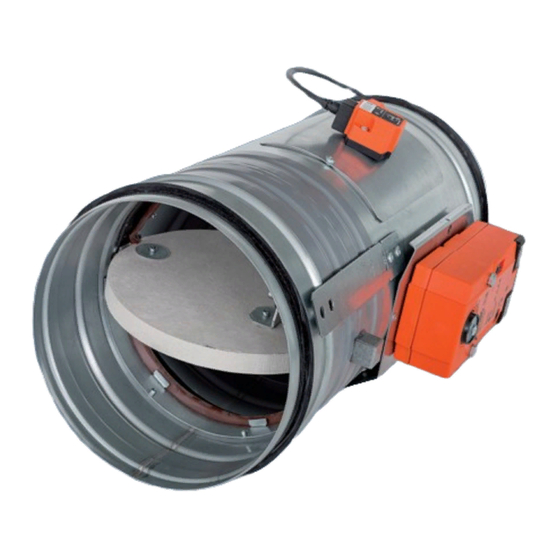
TPM 083/12 3. Dimestions, weights Dimensions 3.1. Fig. 2 Fire damper FDMC Fig. 3 Fire damper smoke relief FDMC-SRD Position: Damper body BAE 72B-S thermoelectrical starting mechanism Damper blade Inspection hole covering Actuating mechanism Park Allé 366, DK-2605 Brondby Telefon 70 20 19 11; E-mail:oeland@oeland.dk... -
Page 6: Placement And Assembly
TPM 083/12 Weight and effective area 3.2. Tab. 3.2.1. Weight and effective area Size Weight Actuating mechanism Effective area 0,0036 0,0068 0,0092 0,0109 0,0129 0,0172 0,0222 0,0293 0,0374 0,0484 41,5 0,0630 0,0793 61,5 0,0821 0,1065 For fire damper the open damper blade overlaps the damper body from dimension 250 by the 3.3. - Page 7 TPM 083/12 To provide needed access space to the control device, all other objects must be situated at least 4.2. 350 mm from the control parts of the damper. Inspection hole must be accessible. The distance between the fire damper and the construction (wall, ceiling) must be minimum 4.3.
-
Page 8: Statement Of Installations
- gypsum wall construction Fig. 7 Installation on a solid wall construction Position: Fire damper FDMC Mortar or gypsum with min. density 800 kg/m or another approved fire sealing system for damper installation Park Allé 366, DK-2605 Brondby... - Page 9 TPM 083/12 Fig. 8 Installation on a gypsum wall construction Position: Fire damper FDMC Mortar or gypsum with min. density 800 kg/m or another approved fire sealing system for damper installation Fig. 9 Installation on a ceiling wall construction Position: Fire damper FDMC Mortar or gypsum with min.
- Page 10 TPM 083/12 Fig. 10 Duct ended by installation shaft - solid wall construction Position: Fire damper FDMC Duct Mortar or gypsum with min. density 800 kg/m or another Installation shaft approved fire sealing system for damper installation Fig. 11 Duct ended by installation shaft - gypsum wall construction...
-
Page 11: Technical Data
TPM 083/12 III. TECHNICAL DATA 6. Pressure loss Pressure loss calculation 6.1. [Pa] presure loss [m.s air flow speed in nominal damper section [kg.m air density coefficient of local pressure loss for the nominal damper section (see Tab. 7.1.1.) Determination of pressure loss by using diagram 6.2.1. = 1,2 kg.m 6.2. -
Page 12: Noise Data
TPM 083/12 8. Noise data Level of acoustic output corrected with filter A. 8.1. + 10 log(S) + K [dB(A)] level of acoustic output corrected with filter A [dB] level of acoustic output L related to the 1 m section (see Tab. 8.3.1.) effective area of the damper [dB] correction to the weight filter A (see Tab. - Page 13 TPM 083/12 Fig. 12 Calculation example Given data: Fire damper FDMC 250 V = 1000 m = 1,2 kg.m Octave range 1000 Hz Tab. 3.2.1. = 0,0374 m Calculation : w [m.s ] = (V [m ] / 3600) / S w = 7,43 m.s...
-
Page 14: Electrical Components, Connection Diagrams
TPM 083/12 9. Electrical Components, Connection Diagrams Actuating mechanism 9.1. Tab. 9.1.1. Actuating mechanism BELIMO BLF 24-T-ST (24-ST) BLF 24-T-ST(24-ST) Servopohon BELIMO Nominal voltage AC 24V 50/60Hz DC 24 V Power consumption - motoring - holding 2,5 W Dimensioning 7 VA (Imax 5,8 A @ 5 ms) Protection Class Degree of protection IP 54... -
Page 15: Ordering Information
TPM 083/12 IV. ORDERING INFORMATION 10. Ordering key FDMC 180 TPM 083/12-DK technical specifications size type (FDMC, FDMC-SRD) V. MATERIAL, FINISHING 11. Material Damper bodies are supplied in the design made of galvanized plate without any other surface 11.1. finish. -
Page 16: Entry Into Service And Revisions
BAE 72B-S - only FDMC or cutting off the supply from ELECTRICAL FIRE SIGNALISATION). Check of blade displacement back into the "OPEN" position can be done after restoration of power supply (e.g. By releasing the RESET button - only FDMC or restoration of supply from ELECTRICAL FIRE SIGNALISATION).
Need help?
Do you have a question about the FDMC and is the answer not in the manual?
Questions and answers