Mandik FDMR Installation Instructions Manual
Fire damper
Hide thumbs
Also See for FDMR:
- Instructions for use manual (14 pages) ,
- Technical documentation manual (38 pages) ,
- Installation, operation, maintenance and service instructions (101 pages)

Related Manuals for Mandik FDMR


Summary of Contents for Mandik FDMR
- Page 2 ≥ 100 ≥ 40 Position: Fire damper Solid wall construction Mortar or gypsum Duct ≥ 100 ≥ 50 ≥ 25 Used materials - example:* Position: Promapyr, Rockwool Steprock HD, Hilti CFS-CT B 1S 140/50 Fire damper Promastop - P, K, Hilti CFS-CT Solid wall construction * Fire resistant insulation and fire resistant board can be Stuffing box (mineral stone wool min.
- Page 3 ≥ 40 ≥ 40 Used materials - example:* ≥ 100 HILTI CFS-CT B 1S 140/50 or ROCKWOOL HARDROCK + coating HILTI CFS-CT Position: HILTI CFS-CT Fire damper HILTI CFS-S ACR Solid wall construction * Fire resistant insulation and fire resistant board can be Stuffing box (mineral stone wool min.
- Page 4 ≥ 100 ≥ 50 ≥ 40 Screw ≥ 25 ≤ 300 (min. 4x50) ≥ 25 ≤ 300 Screws has to be fixed in wall/ceiling construction. (If it is needed use steel bracket). Used materials - example:* Promapyr, Rockwool Steprock HD, Hilti CFS-CT B 1S 140/50 Promastop - P, K, Hilti CFS-CT Position: Promatect - H...
- Page 5 ≥ 100 ≥ 100 ≥ 100 ≥ 100 Position: Fire damper Installation frame Solid wall construction...
- Page 6 D+60 to 800 max. 2050 D+60 to 800 max. 1650 ≥ 100 Used materials - example:* Hilti CFS-CT B 1S 140/50 Position: Hilti CFS-CT Fire damper Solid wall construction * Fire resistant insulation and fire resistant board can be replaced by another approved fire sealing system for Fire resistant board damper installation with equivalent material properties.
- Page 7 ≥ 40* * Around the perimeter ≥ 100 Used materials - example:** DN 100 ÷ DN 800 - System ISOVER_ULTIMATE PROTECT, th. 100 mm - EIS 60 DN 100 ÷ DN 315 - System ISOVER_ULTIMATE PROTECT, th. 120 mm (2x60 mm) - EIS 90 DN 350 ÷...
- Page 8 ≥ 50 ≥ 40 ≥ 400 ≥ 100 variable** ≥ 100 Screw ≥ 25 ≤ 300 (min. 4x50) ≥ 25 ≤ 300 Screws has to be fixed in wall/ceiling construction. (If it is needed use steel bracket). Used materials - example:* Position: Promapyr, Rockwool Steprock HD, Hilti CFS-CT B 1S 140/50 Promastop - P, K, Hilti CFS-CT...
- Page 9 Installation opening has to ≥ 100 be reinforced by profile (UW, CW). Profil is fixed by screws ≥3,5 mm with corre- sponding length. Distance between screws ≤200 mm. ≥ 40 Position: Fire damper Gypsum plate Mineral wool (type depending on the type of construction) Mortar or gypsum Duct ≥...
- Page 10 ≥ 100 Installation opening has to be reinforced by profile (UW, CW). Profil is fixed by screws ≥3,5 mm with corre- sponding length. Distance between screws ≤200 mm. ≥ 40 ≥ 40 Used materials - example:* HILTI CFS-CT B 1S 140/50 or ROCKWOOL HARDROCK + coating HILTI CFS-CT Position: HILTI CFS-CT...
- Page 11 Installation opening has to ≥ 100 be reinforced by profile (UW, CW). Profil is fixed by screws ≥3,5 mm with corre- sponding length. Distance between screws ≤200 mm. ≥ 50 ≥ 40 ≥ 25 ≤ 300 Screw (min. 4x50) ≥ 25 ≤...
- Page 12 Installation opening has to Installation opening has to be reinforced by profile be reinforced by profile (UW, CW). Profil is fixed by (UW, CW). Profil is fixed by screws ≥3,5 mm with corre- screws ≥3,5 mm with corre- sponding length. Distance ≥...
- Page 13 Installation opening has to be reinforced by profile (UW, CW). Profil is fixed by screws ≥3,5 mm with corre- sponding length. Distance between screws ≤200 mm. D+60 to 800 max. 2050 D+60 to 800 max. 1650 ≥ 100 Position: Used materials - example:* Fire damper Hilti CFS-CT B 1S 140/50 Gypsum plate...
- Page 14 The mounting hole must be reinforced with a wooden frame made of 60x60 mm beams. D+60 to 800 max. 2050 D+60 to 800 Used materials - example:* max. 1650 Hilti CFS-CT B 1S 140/50 ≥ 110 Hilti CFS-CT Position: Fire damper Gypsum plate Mineral wool (type depending on the type of construction)
- Page 15 Installation opening has to be reinforced by profile (UW, CW). Profil is fixed by screws ≥3,5 mm with corre- sponding length. Distance between screws ≤200 mm. ≥ 40* * Around the perimeter ≥ 100 Used materials - example:** Position: DN 100 ÷ DN 800 - System ISOVER_ULTIMATE PROTECT, th. 100 mm - EIS 60 Fire damper DN 100 ÷...
- Page 16 Installation opening has to be reinforced by profile (UW, CW). Profil is fixed by screws ≥3,5 mm with corre- sponding length. Distance between screws ≤200 mm. ≥ 50 ≥ 40 variable** ≥ 400 ≥ 100 ≥ 100 Screw ≥ 25 ≤...
- Page 17 ≥ 40 Position: Fire damper Solid ceiling construction * min. 110 - Concrete/ min. 125 - Aerated concrete Mortar or gypsum Duct ≥ 25 ≥ 50 * min. 110 - Concrete/ min. 125 - Aerated concrete Used materials - example:** Position: Promapyr, Rockwool Steprock HD, Hilti CFS-CT B 1S 140/50 Fire damper...
- Page 18 ≥ 50 ≥ 40 ≥ 25 ≤ 300 Screw (min. 4x50) ≥ 25 ≤ 300 Screws has to be fixed in wall/ceiling construction. (If it is needed use steel bracket). * min. 110 - Concrete/ min. 125 - Aerated concrete Used materials - example:* Promapyr, Rockwool Steprock HD, Hilti CFS-CT B 1S 140/50 Position:...
- Page 19 ≥ 40 ≥ 40 * min. 110 - Concrete/ min. 125 - Aerated concrete Used materials - example:** HILTI CFS-CT B 1S 140/50 or ROCKWOOL HARDROCK + coating HILTI CFS-CT Position: HILTI CFS-CT Fire damper HILTI CFS-S ACR Solid ceiling construction ** Fire resistant insulation and fire resistant board can be Stuffing box (mineral stone wool min.
- Page 20 Position: * min. 110 - Concrete/ min. 125 - Aerated concrete Fire damper Installation frame Solid ceiling construction...
- Page 21 D+60 to 800 D+60 to 800 max. 2050 max. 1650 * min. 110 - Concrete/ min. 125 - Aerated concrete Used materials - example:** Hilti CFS-CT B 1S 140/50 Position: Hilti CFS-CT Fire damper Solid ceiling construction ** Fire resistant insulation and fire resistant board can be replaced by another approved fire sealing system for Fire resistant board damper installation with equivalent material properties.
- Page 22 ≥ 40 ≥100 variable*** variable*** ≥ 40 * min. 110 - Concrete/ min. 125 - Aerated concrete Used materials - example:** DN 100 ÷ DN 800 - System ISOVER_ULTIMATE PROTECT, th. 100 mm - EIS 60 DN 100 ÷ DN 315 - System ISOVER_ULTIMATE PROTECT, th. 120 mm (2x60 mm) - EIS 90 Position: DN 350 ÷...
- Page 23 ≥ 40 ≥100 variable** ≥ 400 * min. 110 - Concrete/ min. 125 - Aerated concrete Used materials - example:** Rockwool Wired Mat 105 th. 3x60 mm Position: Rockwool Wired Mat 105 th. 60 mm Fire damper Stuffing box, fire protection mastic, cement lime plate and Solid ceiling construction insulation materials can be replaced by another approved fire sealing system for damper installation with equivalent material...
- Page 24 ≤ 750 ≤ 100 Position: Fire damper Solid ceiling construction Concrete B20 * min. 110 - Concrete/ min. 125 - Aerated concrete Rebar ** Around the perimeter Duct...
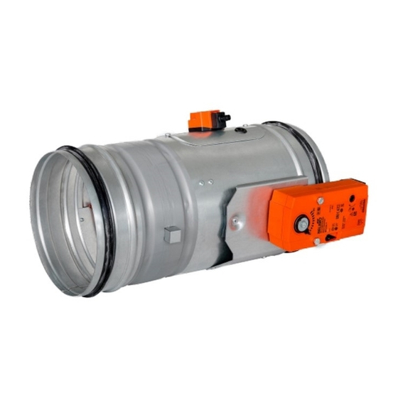
- Page 25 Position: Damper casing Mechanics Damper blade Inspection hole covering Sensor sticker Hole for camera...
- Page 26 Position: Damper casing Mechanics Damper blade Inspection hole covering Sensor sticker Hole for camera...
- Page 27 X=53 mm (BFL) X=72 mm (BFN) X=78 mm (BF) Position: Damper casing Actuating mechanism Damper blade Inspection hole covering BAT thermoelectrical starting mechanism Hole for camera...
- Page 28 X=70 mm (BFL - DN 100 ÷ DN 315) X=53 mm (BFL - DN 355 ÷ DN 400) X=72 mm (BFN) X=78 mm (BF) Position: Damper casing Actuating mechanism Damper blade Inspection hole covering BAT thermoelectrical starting mechanism Hole for camera...
- Page 29 Damper Mounting plate Actuating mechanism Temperature sensor Mounting plate Mechanics Thermal fuse Damper Mounting plate Actuating mechanism Temperature sensor Mounting plate Mechanics Thermal fuse Sensor sticker Hole for temperature sensor / Sensor sticker 10 Inspection hole covering 11 Hole for camera...
- Page 30 During the installation process, the blade position must be “CLOSED”. During the installation process, the control mechanism must be protected against pollution and damage. Fire dampers are suitable for installation in any position in vertical and horizontal passages of fire separating structures.
- Page 31 The damper body must not get deformed during its installation process. Once the damper is built installed, its blade must not grind on the damper body during its opening or closing. To provide needed access space to the control device, all the other objects must be situated at least 350 mm away from the damper control parts.
-
Page 32: Wiring Diagrams
Wiring diagrams N L1 S1 S2 <5° <80° S1 S2 <5° <80° N L1 S1 S2 <5° <80° 1(COM) - black wire 2(NC) - gray wire 4(NO) - blue wire AC 230V / 5A This limit switch is possible to connect in following two versions: IP 67 if the arm is moving …... - Page 33 Before commissioning the dampers and during their subsequent operational checks, it is necessary to check and functionally test all the designs, including the operation of any electronic elements. Upon commissioning, these operational checks must be completed at least twice a year. If no defect is found during two consecutive operational checks, then operational checks may be completed once a year.
- Page 34 • The damper bodies are normally supplied in their galvanized sheet steel design (alternatively stainless steel) without any additional surface finish. • The damper blades are made of asbestos-free fire-resistant mineral fibre boards. • The damper control devices are made of galvanized materials (alternatively of stainless steel) without any additional surface finish.
- Page 35 MANDÍK, a.s. Dobříšská 550 26724 Hostomice Czech Republic Tel.: +420 311 706 706 E-Mail: mandik@mandik.cz www.mandik.com The producer reserves the right for innovations of the product. For actual product information see www.mandik.com...
Need help?
Do you have a question about the FDMR and is the answer not in the manual?
Questions and answers