
Subscribe to Our Youtube Channel
Related Manuals for QUANTA QuantaGrid Series


Summary of Contents for QUANTA QuantaGrid Series
- Page 1 QuantaGrid Series D51PC-1U Versatile Compact 2-Socket Server User’s Guide Version: 1.0...
- Page 2 OPYRIGHT Copyright Copyright © 2014 Quanta Computer Inc. This publication, including all photographs, illus- trations and software, is protected under international copyright laws, with all rights reserved. Neither this technical guide, nor any of the material contained herein, may be reproduced without the express written consent of the manufacturer.
-
Page 3: Table Of Contents
ABLE OF ONTENT ABLE OF ONTENT About the System Introduction ............1-1 Package Contents . - Page 4 ABLE OF ONTENT Server Management Screen........2-8 Boot Options Screen.
- Page 5 ABLE OF ONTENT Front Panel User Interface ........3-2 Power Button .
- Page 6 ABLE OF ONTENT Server Component ..........3-19 Server identify .
- Page 7 ABLE OF ONTENT Regulatory and Compliance Information...
- Page 8 ONVENTIONS Conventions Several different typographic conventions are used throughout this manual. Refer to the following examples for common usage. Bold type face denotes menu items, buttons and application names. Italic type face denotes references to other sections, and the names of the folders, menus, programs, and files.
- Page 9 RECAUTIONARY EASURES Precautionary Measures Read all caution and safety statements in this document before performing any of the instructions. To reduce the risk of bodily injury, electrical shock, fire, and equipment dam- age, read and observe all warnings and precautions in this chapter before installing or maintaining your system.
- Page 10 RECAUTIONARY EASURES Table 1: Warning and Cautions (Continued) The enclosure is designed to carry only the weight of the system sled. Do not use this equipment as a workspace. Do not place additional load onto any equipment in this system. Indicates two people are required to safely handle the system.
- Page 11 RECAUTIONARY EASURES Equipment Handling Practices Reduce the risk of personal injury or equipment damage: Conform to local occupational health and safety requirements when moving and lifting equipment. Use mechanical assistance or other suitable assistance when moving and lifting equipment.
- Page 12 RECAUTIONARY EASURES Rack Mount Warnings The following installation guidelines are required by UL for maintaining safety compliance when installing your system into a rack. The equipment rack must be anchored to an unmovable support to prevent it from tip- ping when your system or piece of equipment is extended from it. The equipment rack must be installed according to the rack manufacturer's instructions.
- Page 13 RECAUTIONARY EASURES Electrostatic Discharge (ESD) CAUTION! CAN DAMAGE DRIVES BOARDS AND OTHER PARTS E RECOMMEND THAT YOU PERFORM ALL PROCEDURES AT AN WORKSTATION F ONE IS NOT AVAILABLE PROVIDE SOME PROTECTION BY WEARING AN ANTI STATIC WRIST STRAP ATTACHED TO CHASSIS GROUND ANY UNPAINTED METAL SURFACE ON YOUR SERVER WHEN HANDLING PARTS...
- Page 14 RECAUTIONARY EASURES ified in this manual. Use of other products / components will void the UL listing and other regulatory approvals of the product and will most likely result in non-compliance with product regulations in the region(s) in which the product is sold. System power on/off: To remove power from system, you must remove the system from rack.
- Page 15 RECAUTIONARY EASURES Assembly Safety Guidelines The power system in this product contains no user-serviceable parts. Refer servicing only to qualified personnel. The system is designed to operate in a typical office environment. Choose a site that is: Clean and free of airborne particles (other than normal room dust). ...
- Page 16 RECAUTIONARY EASURES Structure of this guide Chapter 1: About the System “This section introduces the system, its different configuration(s) and the main features.” Chapter 2: BIOS “This section provides information regarding the BIOS architecture, BIOS update utility, server management, checkpoints, and error handling found in the sys- tem.”...
- Page 17 About the System Chapter 1 This section introduces the system, its different configuration(s) and the main features.
-
Page 18: 1.1 Introduction
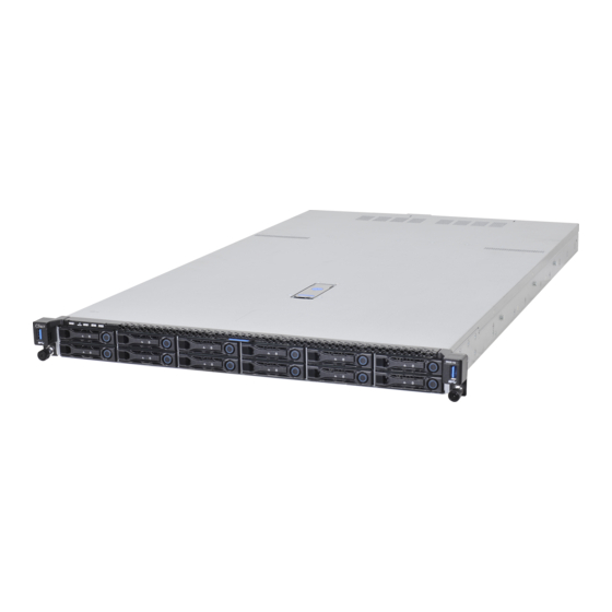
The QuantaGrid D51PC-1U can accommodate one PCIe x8 OCP mezzanine, one PCIe x8 Quanta LAN or SAS mezzanine, plus one PCIe x8 low-profile card (adding up to 12 GbE ports in a 1U chassis). The server can sup- port one fan rotor and PSU redundancy to maintain reliable application perfor- mance even if one of these critical components fails. - Page 19 Quanta LSI® 2308 6Gb/s SAS mezzanine, RAID 0, 1, 10 Quanta LSI® 3008 12Gb/s SAS mezzanine, RAID 0, 1, 10 Quanta LSI® 2208 6Gb/s RAID mezzanine, RAID 0, 1, 5, 10 (RAID 6 with additional RAID key) LOM: Option 1 ...
- Page 20 BOUT THE YSTEM NTRODUCTION Table 1.1: System Specifications (Continued) PECIFICATIONS ESCRIPTION Video Integrated Aspeed AST2400 with 8MB DDR3 video memory 2.5" SKU None Front I/O 3.5" SKU 2x USB 2.0 ports 2x USB 3.0 ports 1x VGA port ...
-
Page 21: 1.2 Package Contents
(2) processor heat sinks (1) power supply unit (1) power cord (optional) (1) utility CD (This guide included) (1) rail kit (Instruction sheet included) Note: Note: For exact shipping contents, contact your Quanta sales representative. -
Page 22: 1.3 A Tour Of The System
Supports x8 PCIe 3.0 LP MD-2 PCIe card only Expansion slot Supports OCP mezzanine only Mainboard System mainboard Expansion slot Supports Quanta mezzanine only PSU assembly Redundant power supply unit assembly Power Distribution Board Backup battery Backup battery for mezzanine card ... -
Page 23: System Front View
BOUT THE YSTEM YSTEM RONT System Front View Figure 1-2. 2.5” System Front View Figure 1-3. 3.5” System Front View Table 3: Front Panel View ESCRIPTION Front control panel See Front Control Panel LED on page 1-10 for further information. ... -
Page 24: Front Control Panel
BOUT THE YSTEM YSTEM RONT Front Control Panel For purposes of this procedure, the 3.5” FCP is used for the numbering indicators. There are no USB ports on the 2.5” FCP. Figure 1-4. 3.5” Front Control Panel Figure 1-5. 2.5” Front Control Panel Table 4: Front Control Panel Definition ESCRIPTION USB ports... -
Page 25: System Rear View
System Rear View Figure 1-6. System Rear View Table 5: System Rear View EATURE ESCRIPTION Expansion slot Supports Quanta mezzanine only Expansion slot Supports OCP mezzanine only Expansion slot Supports x8 PCIe 3.0 LP MD-2 PCIe card only System I/O ports... -
Page 26: Power Sub-System
BOUT THE YSTEM YSTEM Table 6: System Rear I/O Defintition (Continued) ESCRIPTION Press to light up blue to identify the system. Press again to turn ID button with LED the ID LED off. NIC3 RJ45 connector NIC4 RJ45 connector USB port USB 3.0 port 0 USB port USB 3.0 port 1... -
Page 27: Led Status Definitions
LED S BOUT THE YSTEM TATUS EFINITIONS LED Status Definitions Front Control Panel LED For further information and location of the FCP LEDs, see Front Control Panel LED on page 1-10. Figure 1-9. 2.5” System Front Control Panel LEDs Figure 1-10. 3.5” System Front Control Panel LEDs Table 8: Front Control Panel LED Behavior OLOR ONDITION... -
Page 28: Lan Led
LED S BOUT THE YSTEM TATUS EFINITIONS LAN LED The system mainboard includes an optional dual 1GbE network with 1GbE dedicated management port with an optional 10G SPF+ OCP network mezzanine card. Each RJ45 connector has two built-in LEDs. See the following illustration and table for details. Link / Activity Speed PIN 1... -
Page 29: Hdd Led
LED S BOUT THE YSTEM TATUS EFINITIONS HDD LED The following LED behavior table represents LED conditions when a driver is online and the slot is not empty. Table 11: HDD LED Status Behavior OLOR ONDITION ESCRIPTION Drive is online HDD Status* Blue Slot is empty... -
Page 30: Bios
BIOS Chapter 2 This section provides information regarding the BIOS architecture, BIOS update utility, server management, checkpoints, and error handling found in the system. -
Page 31: 2.1 Bios Setup Utility
The Keyboard Command Bar is located at the bottom right of the screen and con- mand Bar tinuously displays help for keyboard special keys and navigation keys. Entering BIOS Setup BIOS Setup is started by pressing <DEL> or <F2> during boot time when the OEM (Quanta) logo is displayed. -
Page 32: Keyboard Commands
BIOS EYBOARD OMMANDS When Quiet Boot is disabled, the message “press <DEL> or <F2> to enter setup” will be displayed on the diagnostics screen. Keyboard Commands The bottom right portion of the Setup screen provides a list of commands that are used to navigate through the Setup utility. -
Page 33: Menu Selection Bar
BIOS ELECTION Table 2: Keyboard Commands (Continued) PTION ESCRIPTION The minus key on the keypad is used to change the value of the cur- Change Value rent item to the previous value. This key scrolls through the values in the associated pick list without displaying the full list. The plus key on the keypad is used to change the value of the current menu item to the next value. -
Page 34: Server Platform Setup Utility Screens
BIOS ERVER LATFORM ETUP TILITY CREENS Server Platform Setup Utility Screens The sections below describe the screens available for the configuration of a server plat- form. In these sections, tables are used to describe the contents of each screen. These tables follow the following guidelines: The text and values in the Setup Item, Options, and Help columns in the tables are ... -
Page 35: Advanced Screen
BIOS DVANCED CREEN Table 3: Main Screen Description ETUP PTIONS OMMENTS Information only. Displays the BIOS Vendor BIOS Vendor. Information only. Displays the Core Version AMI BIOS Core version. Information only. Displays the Compliancy BIOS compliancy. Information only. Displays the Project Version Project version. - Page 36 BIOS DVANCED CREEN To access this screen from the Main screen, press the right arrow until the Advanced screen is chosen. Figure 2-2. Advanced Screen Table 4: Advanced Screen Description ETUP PTIONS OMMENTS System Super IO Chip Parame- Super IO Configuration ters.
-
Page 37: Intelrcsetup Screen
BIOS DVANCED CREEN IntelRCSetup Screen The IntelRCSetup screen provides an access point to configure several options. On this screen, you can select the option that is to be configured. Configurations are performed on the selected screen, not directly on the IntelRCSetup screen. To access this screen from the Main screen, press the right arrow until the IntelRCSetup screen is chosen. -
Page 38: Server Management Screen
BIOS ERVER ANAGEMENT CREEN Table 5: IntelRCSetup Screen Description (Continued) ETUP PTIONS OMMENTS Memory Config- Displays and provides option to uration change the Memory Settings IIO Configura- Displays and provides option to tion change the IIO Settings PCH Configura- Displays and provides option to tion change the PCH Settings Server ME Con-... - Page 39 BIOS ERVER ANAGEMENT CREEN Table 6: Server Management Screen Description (Continued) ETUP PTIONS OMMENTS BMC firmware Information only. Displays the version BMC firmware version. Information only. Displays the IPMI version IPMI version. [Disabled] Enable or Disable FRB-2 timer Not available if FRB2 Timer is dis- FRB-2 Timer (POST timer) abled.
-
Page 40: Boot Options Screen
BIOS PTIONS CREEN Boot Options Screen The Boot Options screen displays any bootable media encountered during POST, and allows the user to configure desired boot device. If no boot devices are available – for example, both onboard LAN are disabled and no bootable device connected when Boot Mode is set to Legacy –... -
Page 41: Security Screen
BIOS ECURITY CREEN Table 7: Boot Options Screen Description (Continued) ETUP PTIONS OMMENTS This item decides what devices (Legacy or UEFI) BIOS should try [LEGACY] Boot mode Select boot mode LEGACY/UEFI to boot when let the system auto select [UEFI] boot up without manually select boot device. -
Page 42: Exit Screen
BIOS CREEN To access this screen from the Main screen, select the Security option. Figure 2-6. Security Screen Table 8: BIOS Screen Description ETUP PTIONS OMMENTS Administrator Set Administrator Password Password User Password Set User Password Secure Boot Customizable Secure Boot set- menu tings Exit Screen... - Page 43 BIOS CREEN the user saved earlier, instead of being restored to the factory defaults. For boot devices, BIOS only supports at most six USB boot devices. Figure 2-7. Exit Screen Table 9: Exit Screen Description ETUP PTIONS OMMENTS Discard Changes and Exit system setup without Exit saving any changes.
-
Page 44: Loading Bios Defaults
BIOS BIOS D OADING EFAULTS Loading BIOS Defaults Different mechanisms exist for resetting the system configuration to the default values. When a request to reset the system configuration is detected, the BIOS loads the default system configuration values during the next POST. The request to reset the system to the defaults can be sent in the following ways: A request to reset the system configuration can be generated by pressing <F9>... -
Page 45: 2.2 Bios Update Utility
BIOS BIOS U PDATE TILITY 2.2 BIOS Update Utility The flash ROM contains system initialization routines, the BIOS Setup Utility, and runtime support routines. The exact layout is subject to change, as determined by BIOS. The flash ROM also contains initialization code in compressed form for onboard peripherals, like SCSI, NIC and video controllers. -
Page 46: Bios Setting Utility
BIOS CMOS LEAR Memory reference code. Microcode updates. ME Firmware. BIOS Setting Utility Use AMISCE to import/export BIOS setting in Linux: 1. Export BIOS setting and generate script file: /o /s NVRAM.txt 2. Import BIOS setting with script file: /i /s NVRAM.txt BIOS Revision The BIOS revision is used to identify the BIOS image and BIOS phase. -
Page 47: Bios Update Via Bmc Instructions (Optional)
BIOS BIOS U BMC I PDATE NSTRUCTIONS PTIONAL BIOS Update Via BMC Instructions (Optional) In order to prevent BIOS corruption during upgrade process due to power failure or unex- pected interrupt, “BIOS update via BMC instructions” provides a safe mechanism which allow server manager to rebuild server BIOS through BMC. -
Page 48: 2.3 Server Management
BIOS ERVER ANAGEMENT 2.3 Server Management The BIOS supports many standard-based server management features and several propri- etary features. The Intelligent Platform Management Interface (IPMI) is an industry stan- dard and defines standardized, abstracted interfaces to platform management hardware. The BIOS implements many proprietary features that are allowed by the IPMI specification, but these features are outside the scope of the IPMI specification. -
Page 49: Reset
BIOS ONSOLE EDIRECTION Table 10: Keystroke Mappings (Continued) ANSI E SCAPE EQUENCE INDOWS LATFORM ESIGN <ESC>8 <ESC>9 <ESC>0 <ESC>! <ESC>@ Home <ESC>[<Shift>h <ESC>h <ESC>[<Shift>k <ESC>k <ESC>+ <ESC>- Page Up <ESC>? Page Down <ESC>/ Reset <ESC>R<ESC>r<ESC>R Standalone <Esc> Key for Headless Operation The Microsoft Headless Design Guidelines describes a specific implementation for the <Esc>... -
Page 50: Interface To Server Management (Optional)
BIOS BIOS S ETWORK UPPORT Interface to Server Management (Optional) If the BIOS determines that console redirection is enabled, it will read the current baud rate and pass this value to the appropriate management controller via the Intelligent Plat- form Management Bus (IPMB). Network BIOS Support PXE Boot The BIOS supports the EFI PXE implementation. - Page 51 BIOS HECKPOINTS b. Error code (POST Error/ MRC Fatal/Warning Code One reset switch (To trigger system reset) 2-21...
- Page 52 Chapter 3 This section provides information and key features of BMC (Baseboard Management Controller).
-
Page 53: 3.1 Server Management Software
ERVER ANAGEMENT OFTWARE 3.1 Server Management Software Server System Overview In a server system, BMC is an independent system of the host server system. This indepen- dent system has its own processor and memory; the host system can be managed by the BMC system even if the host hardware or OS hangs or is unable to function. -
Page 54: Front Panel User Interface
RONT ANEL NTERFACE Front Panel User Interface The BMC provides control panel interface functionality including indicators (Fault/status and Identify LEDs) and buttons (Power/ID). Power Button The Power buttons allow to control the system status. ID Button The control panel Chassis Identify button toggles the state of the Chassis ID LED. If the ID LED is off, then a button press will turn the LED on (blinking). -
Page 55: Session And User
ERIAL Obtain System Event Log (SEL) entries Obtain Sensor Data Records (SDR) Set Platform Event Filtering (PEF) Set LAN configurations In addition, the BMC supports LAN alerting in the form of SNMP traps that conform to the IPMI Platform Event Trap (PET) format. -
Page 56: Bmc Firmware Update
BMC F IRMWARE PDATE All Platform Event Filter Table is default disabled. PEF Startup Delay and Last Processed Event tracking is not supported. PEF table lookup isn’t correlated to log SEL to SEL Repository. Serial Alerting is no support. ... -
Page 57: 3.2 Bmc Recovery
BMC R ECOVERY 3.2 BMC Recovery This section provides guidelines on BMC recovery process in DOS and Linux systems. Recovery Process in DOS System To recover BMC on a DOS system, do as follows: 1. Copy BMC firmware package to your USB key. 2. -
Page 58: 3.3 Smash
SMASH 3.3 SMASH Quanta SMASH is a tool that allows you to use Secure Shell (SSH) to login in the embedded Linux of BMC from remote terminal and gather information as well as give you control over things like power resets, power off. The basic structure is shown as below: Figure 3-1. -
Page 59: System Level Commands
SMASH Input command in Linux: ssh sysadmin@<Server IP> Figure 3-2. SMASH Activity Diagram Here provides you the commands about system level and BMC level. System Level Commands The system level commands provide you the information and power state control. Table 3.2: Targets and Verbs UPPORTED ERBS ELATED... - Page 60 SMASH Power-on system start /SYS Power-off system stop /SYS Power-reset system reset /SYS Display all system voltage show /SYS/voltage Display all system fan show /SYS/fan Display all system temperature show /SYS/temperature Display all system power supply show /SYS/powerSupply /SYS This command provides you the hig-level status of the system chassis and main power subsystem.
- Page 61 SMASH /SYS/voltage This command returns a high level version of the system voltages health status. Table 3.4: /SYS/voltage ROPERTY ALID ALUE CCESS ESCRIPTION indicates the status not available /unknown (typically because system power is off) indicates the monitored parameters within nor- mal operating ranges Sensor name list of vlotage...
- Page 62 SMASH Table 3.6: /SYS/temperature ROPERTY ALID ALUE CCESS ESCRIPTION indicates the status not available /unknown (typically because system power is off) indicates the monitored parameters within nor- mal operating ranges Sensor name list of temperature nonCritical nonCritical critical indicates the hardware outside normal operat- ing range critical indicates the hardware exceeding specified rat-...
-
Page 63: Bmc Information
SMASH A1: The other power supply status is " AllDeasserted ". Q2: My system supports two power supply slots and two power supply units connected. But only one power cord plugged. What is the other power supply status? A2: The other power supply status shows "Presence, PredictiveFail, InputLost(AC/DC) ". BMC Information The BMC level commands provide several options to configure and display parameters of the management agent. - Page 64 SMASH Table 3.9: /SYS/fan (Continued) ROPERTY ALID ALUE CCESS ESCRIPTION ServerIdentify Configuring server identify LED blinking Display the NIC physical address used by server BMCMAC management agent 3-12...
-
Page 65: Web Graphical User Interface (Gui) For Esms
(GUI) ESMS RAPHICAL NTERFACE 3.4 Web Graphical User Interface (GUI) for ESMS Using the Web GUI The BMC firmware features an embedded web server enabling users to connect to the BMC using a Web browser (e.g. Microsoft Internet Explorer). The Web GUI shows system information, system events, system status of managed servers, and other system-related information. -
Page 66: Dashboard
ASHBOARD Table 4: Default Username and Password IELD EFAULT Username admin Password admin After passing authentication, the following web page appears. Note: The default username and password are in lowercase characters. It is advised to change the admin password once you have logged in. Click the Help button on the right corner of the page for assistance, the Refresh button to refresh the page, or the Logout button to exit. -
Page 67: Device Information
The maximum MAC address of system LAN port is 8. From Grant-key System MAC platform, BMC support to show LAN Card Type (LOM/OCP Mezzanine/ Quanta Mezzanine) for System MAC. BMC Date & Time The current time of BMC system. BMC Chipset This field shows BMC chipset type. -
Page 68: Network Information
ERVER NFORMATION Network Information The Network Information of the device with the following fields is shown in the following table. To edit the network Information, click Edit. Table 7: Network Information ESCRIPTION Host Name Read only field showing the DNS Hostname of the device. MAC Address Read only field showing the IP address of the device. -
Page 69: Fru Information
FRU I NFORMATION FRU Information Server Component Server Identify BIOS POST Code The following screenshot displays the Server Information menu items: Figure 3-6. Server Information – Menu FRU Information In the MegaRAC GUI, the FRU Information Page displays the BMC FRU file information. The information displayed in this page is Basic Information, Common Header Information, Chassis Information, Board Information and Product Information of the FRU device. - Page 70 FRU I NFORMATION To open the FRU Information Page, click on FRU Information on top menu. Select a FRU Device ID from the Basic Information section to view the details of the selected device. A screenshot of FRU Information page is shown as follows: Figure 3-7.
-
Page 71: Server Component
FRU I NFORMATION Board Manufacturer Board Product Name Board Serial Number Board Part Number FRU File ID Board Extra Product Information Product Information Area Format Version Language Manufacturer Name Product Name ... -
Page 72: Server Identify
FRU I NFORMATION Table 5: Component Information Page (Continued) ESCRIPTION Displays the following information: Memory ID, Status, Socket, Memory Information Module Size, Model, Frequency, and Memory type*. Note: DDR3 ECC or non-ECCUDIMM, RDIMM and LRDIMM memory types support both normal volt- age (1.5V) and low voltage (1.35V). -
Page 73: Bios Post Code
FRU I NFORMATION Table 6: Server Identify Page (Continued) ESCRIPTION Server timeout value when a Blink Identify Operation is selected. For Server Identify Timeout Blink Operation the time period must be from 1 to 255 seconds. When 255 seconds is selected, the blinking is continuous. Perform Action Executes the selected Server Identify Operation. -
Page 74: Sensor Readings
FRU I NFORMATION The Server Health screenshot allows to select Sensor Readings or Event Log as shown in the following image: Figure 3-11. Server Health – Menu Sensor Readings In MegaRAC GUI, the Sensor Readings page displays all the sensor related information. To open the Sensor readings page, click Server Health >... - Page 75 FRU I NFORMATION you want to display in the list. Some examples of other sensors include Temperature Sen- sors, Fan Sensors, and Voltage Sensors etc. Select a particular sensor from the list. On the right hand side of the screen you can view the Thresholds for this sensor.
-
Page 76: Event Log
FRU I NFORMATION View this Event Log View the Event Log page for the selected sensor. Sensor Reading status You can read currently sensor status in this page, each sensor name have its SDR setting data in BMC function SPEC, the status according SDR setting will display as following matrix: Table 8: Sensor Readings status TATUS... - Page 77 FRU I NFORMATION Table 9: Event Log Page ESCRIPTION The category options: All Events, System Event Records, BIOS Gener- ated Events, SMI Handler Events, System Management Software Events, Event Log Category System Software - OEM Events, Remote Console software Events, Termi- nal Mode Remote Console software Events.
-
Page 78: Configuration Group
ONFIGURATION ROUP Configuration Group Configuration Group page allows access to various configuration settings. A screenshot of the Configuration Group menu is shown in the following figure: Figure 3-15. Configuration Group Menu A detailed description of the Configuration menu is given in the following sections. Active Directory An active directory is a directory structure used on Microsoft Windows based computers and servers to store information and data about networks and domains. - Page 79 ONFIGURATION ROUP Table 10: Active Directory Settings Page (Continued) ESCRIPTION The name that identifies the role group in the Active Directory. Note: Role Group ID Role Group Name is a string of 64 alpha-numeric characters. Special symbols (hyphen and underscore) are allowed. This name identifies the role group in Active Directory.
- Page 80 ONFIGURATION ROUP 5. Specify the time (in seconds) to wait for Active Directory queries to complete in the Time Out field. Note: Default Time out value: 120 seconds. Range from 15 to 300 allowed. 6. Configure IP addresses in Domain Controller Server Address1, Domain Control- ler Server Address2 &...
-
Page 81: Dns
ONFIGURATION ROUP 13. Click Add to save the new role group and return to the Role Group List. 14. Click Cancel to cancel the settings and return to the Role Group List. To modify a Role Group 15. In the Advanced Directory Settings Page, select the row that you wish to modify and click Modify Role Group. - Page 82 ONFIGURATION ROUP Table 11: DNS Server Settings Page ESCRIPTION Host configuration Host Settings Choose either Automatic or Manual settings. It displays hostname of the device. If the Host setting is chosen as Man- Host Name ual, then specify the hostname of the device. Register BMC Register BMC To enable/disable Register BMC.
-
Page 83: Ldap/E-Directory
ONFIGURATION ROUP 1. Choose the Host Configuration either Automatic or Manual. Note: If you choose Automatic, you need not enter the Host Name and if you choose Manual, you need to enter the Host Name. 2. Enter the Host Name in the given field if you have chosen Manual Configuration. 3. - Page 84 ONFIGURATION ROUP To open LDAP Settings page, click Configuration > LDAP from the main menu. A sample screenshot of LDAP Settings Page is shown in the screenshot below. Figure 3-20. LDAP Settings Page The fields of LDAP Settings Page are explained below. Table 12: LDAP Settings Page ESCRIPTION To configure LDAP Advanced Settings.
- Page 85 ONFIGURATION ROUP 3. Enter the IP address of LDAP server in the IP Address field. Note: IP Address made of 4 numbers separated by dots as in 'xxx.xxx.xxx.xxx' . Each Number ranges from 0 to 255. First Number must not be 0. ...
-
Page 86: Mouse Mode
ONFIGURATION ROUP Note: Search Base is a string of 255 alpha-numeric characters. Special symbols hyphen, underscore and dot are allowed. 11. In the Role Group Privilege field, enter the level of privilege to assign to this role group. 12. -
Page 87: Network
ONFIGURATION ROUP Table 13: Mouse Mode Settings Page (Continued) ESCRIPTION Save To save any changes made. Reset To Reset the modified changes. Procedure: 1. Choose either of the following as your requirement: Set mode to Absolute Note: Applicable for all Windows versions; RHEL Linux versions not below than RHEL6; Fedora Linux versions not below than FC14. - Page 88 ONFIGURATION ROUP To open Network Settings page, click Configuration > Network from the main menu. A sample screenshot of Network Settings Page is shown in the screenshot below. Figure 3-24. Network Settings Page The fields of Network Settings page are explained below. 3-36...
- Page 89 ONFIGURATION ROUP Table 14: Network Settings Page ESCRIPTION LAN Interface Lists the LAN interfaces. LAN Settings To enable or disable the LAN Settings. This field displays the MAC Address of the device. This is a read only MAC Address field. This option lists the IPv4 configuration settings.
-
Page 90: Pef
ONFIGURATION ROUP Table 15: Reserved IPv6 Address REFIX LLOCATION EFERENCE REFIX LLOCATION EFERENCE 0000::/8 Reserved by IETF [RFC4291] c000::/3 Reserved by IETF [RFC4291] 0100::/8 Reserved by IETF [RFC4291] e000::/4 Reserved by IETF [RFC4291] 0200::/7 Reserved by IETF [RFC4048] f000::/5 Reserved by IETF [RFC4291] 0400::/6 Reserved by IETF... - Page 91 ONFIGURATION ROUP this ratio of pre?]configured entries to run?]time configurable entries can be reallocated if necessary. Figure 3-25. PEF Management – Event Filter The fields of PEF Management – Event Filter Tab are explained below. This page contains the list of configured PEF’s. Table 16: PET Management - Event Filter ESCRIPTION PEF ID...
- Page 92 ONFIGURATION ROUP 2. Select one of PEF ID list and click Modify to modify event Filter entry page. A sample screenshot of modify Event Filter Page is in seen the screenshot below. Figure 3-26. Add Event Filter Entry Page 3. In the Event Filter Configuration section, PEF ID displays the ID for configured PEF entry (read?]only).
- Page 93 ONFIGURATION ROUP Alert Policy Tab This page is used to configure the Alert Policy and LAN destination. You can add, delete or modify an entry in this page. Figure 3-27. PEF Management – Alert Policy The fields of the PEF Management – Alert Policy Tab are explained below. Table 17: PEF Management - Alert Policy ESCRIPTION Displays Policy entry number for the newly configured entry (read-...
- Page 94 ONFIGURATION ROUP Table 17: PEF Management - Alert Policy (Continued) ESCRIPTION To choose a particular destination from the configured destination list. Note: Destination Selector LAN Destination has to be configured - under Configuration -> PEF -> LAN Destination. Modify To modify the existing entries. Delete To delete Alert Policy list.
- Page 95 ONFIGURATION ROUP 10. In the Alert String Key field, choose any one value that is used to look up the Alert String to send for this Alert Policy entry. 11. Click Add to save the new alert policy and return to Alert Policy list. 12.
- Page 96 ONFIGURATION ROUP Table 18: PEF Management - LAN Destination (Continued) ESCRIPTION If Destination type is SNMP Trap, then enter the IP address of the system that will receive the alert. Destination address will support the follow- ing: Destination Address IPv4 address format.
- Page 97 ONFIGURATION ROUP Configuring the SNMP: 1. Navigate to PEF Management. 2. Select LAN Destination tab in Configuration section. 3. Select from LAN Destination menu SNMP Trap. Figure 3-31. Selecting SNMP Trap A Modify LAN Destination entry menu opens. 4. Key in an IP address to the Destination Address field. 5.
-
Page 98: Radius
ONFIGURATION ROUP RADIUS RADIUS is a modular, high performance and feature-rich RADIUS suite including server, cli- ents, development libraries and numerous additional RADIUS related utilities. In MegaRAC GUI, this page is used to set the RADIUS Authentication. To open RADIUS Settings page, click Configuration > RADIUS from the main menu. A sam- ple screenshot of RADIUS Settings Page is shown in the screenshot below. -
Page 99: Remote Session
ONFIGURATION ROUP Table 19: RADIUS Settings Page (Continued) ESCRIPTION Save To save the settings. Reset To reset the modified changes. Procedure: 1. Enable the RADIUS Authentication checkbox to authenticate the RADIUS. 2. Enter the port number in the Port Number field. 3. -
Page 100: Smtp
ONFIGURATION ROUP Table 20: Remote Session Settings Page (Continued) ESCRIPTION Two types of VM attach mode are available: Attach: Immediately attaches Virtual Media to the server upon Virtual Media Attach Mode bootup. Auto Attach: Attaches Virtual Media to the server only when a virtual media session is started. - Page 101 ONFIGURATION ROUP To open SMTP Settings page, click Configuration > SMTP from the main menu. A sample screenshot of SMTP Settings Page is shown in the screenshot below. Figure 3-35. SMTP Settings Page The fields of SMTP Settings Page are explained below. Table 21: SMTP Settings Page ESCRIPTION LAN Channel Number...
- Page 102 ONFIGURATION ROUP Table 21: SMTP Settings Page (Continued) ESCRIPTION The username to access SMTP Accounts. Note: User Name can be of length 4 to 64 alpha-numeric characters. Username It must start with an alphabet. Special characters ' , '(comma), ':'(colon), ';'(semicolon), ' '(space) and '\'(backslash) are not allowed.
-
Page 103: Sol
ONFIGURATION ROUP Here, you can configure the Serial over LAN settings, select or change values for each attri- bute and click the Save button to save any changes. Figure 3-36. SOL Settings Page The fields of SOL Settings Page are explained below. Table 22: SOL Settings Page ESCRIPTION Enable Serial over LAN... - Page 104 ONFIGURATION ROUP View SSL option is used to view the uploaded SSL certificate in readable format. A sample screenshot of SSL Management Page is shown in the screenshot below. Figure 3-37. SSL Certificate Configuration – Upload SSL The fields of SSL Certificate Configuration – Upload SSL tab are explained below. Table 23: SSL Certificate Configuration - Upload SSL ESCRIPTION Current Certificate...
- Page 105 ONFIGURATION ROUP Table 24: SSL Certificate Configuration - Generate SSL ESCRIPTION Common name for which certificate is to be generated. Common Name (CN) Maximum length of 64 characters. Special characters '#' and '$' are not allowed. Organization name for which the certificate is to be generated. Organization (O) ...
- Page 106 ONFIGURATION ROUP Figure 3-39. SSL Certificate Configuration – View SSL The fields of SSL Certificate Configuration – View SSL tab are explained below. Table 25: SSL Certificate Configuration – View SSL ESCRIPTION This section displays the basic information about the uploaded SSL cer- tificate.
-
Page 107: User Management
ONFIGURATION ROUP Procedure: 1. Click the Upload SSL Tab, Browse the New Certificate and New Privacy key. 2. Click Upload to upload the new certificate and privacy key. 3. In Generate SSL tab, enter the following details in the respective fields The Common Name for which the certificate is to be generated. - Page 108 ONFIGURATION ROUP To open User Management page, click Configuration > Users from the main menu. A sample screenshot of User Management Page is shown in the screenshot below. Figure 3-40. User Management The fields of User Management Page are explained below. Table 26: User Management Page ESCRIPTION Displays the ID number of the user.
- Page 109 ONFIGURATION ROUP 1. To add a new user, select a free slot and click Add User. This opens the Add User screen as shown in the screenshot below. Figure 3-41. Add User Page 2. Enter the name of the user in the User Name field. Note: ...
- Page 110 ONFIGURATION ROUP 9. Choose the Encryption algorithm to use for SNMP settings from the Privacy proto- col dropdown list. 10. In the Email ID field, enter the email ID of the user. If the user forgets the password, the new password will be mailed to the configured email address. Note: SMTP Server must be configured to send emails.
-
Page 111: Virtual Media
ONFIGURATION ROUP 18. To delete an existing user, select the user from the list and click Delete User. Note: There is a list of reserved users which cannot be added / modified as BMC users. Please Refer “MEGARAC SP-X Platform Porting Guide” section “Changing the Configurations in PMC File-> User Configurations in PMC File”... -
Page 112: Snmp
SNMP Note: Maximum of two devices can be added in Floppy, CD/DVD and Hard disk drives. 2. Enable the Local Media Support if needed. 3. Click Save to save the changes made else click Reset to reset the previously saved values. -
Page 113: Lan Port Settings
LAN P ETTINGS Here you can configure UTC timezone setting of the clock in BMC. Figure 3-44. UTC Timezone Table 29: UTC Timezone ESCRIPTION UTC Timezone Timezone of the clock in BMC Procedure: 1. Select UTC Timezone from the dropdown list 2. -
Page 114: Remote Control
EMOTE ONTROL Procedure: 1. Select LAN Port from the dropdown list 2. Click Save to save the change or click Reset to reset the previously saved values. Remote Control The Remote Control consists of the following menu items. Console Redirection ... - Page 115 EMOTE ONTROL Ubuntu 9.10 LTS - 32 Ubuntu 9.10 LTS - 64 Ubuntu 8.10 -32 Ubuntu 8.10 -64 OpenSuse 11.2 -32 OpenSuse 11.2 -64 FC 9 - 32 FC 9 - 64 FC 10 - 32 ...
- Page 116 EMOTE ONTROL Java Console This is an OS independent plug-in which can be used in Windows as well as Linux with the help of JRE. JRE should be installed in the client’s system. You can install JRE from the fol- lowing link.
- Page 117 EMOTE ONTROL Table 30: Video ESCRIPTION Pause redirection This option is used for pausing Console Redirection. This option is used to resume the Console Redirection when the session Resume Redirection is paused. This option can be used to update the display shown in the Console Refresh Video Redirection window.
- Page 118 EMOTE ONTROL Table 31: Keyboard (Continued) ESCRIPTION This menu item can be used to act as the right-side <WIN> key when in Right Windows Key Console Redirection. You can also decide how the key should be pressed: Hold Down or Press and Release. This menu item can be used to act as if you depressed the <CTRL>, Alt+Ctrl+Del <ALT>...
- Page 119 EMOTE ONTROL Table 33: Options ESCRIPTION Note: A behavior changed from Grantley as follows: When [Keyboard->Full Keyboard Support] and [Mouse-> Other mouse mode] enabled at the same time, the mouse will NOT be moved to outside window unless to press “Alt+Tab” to switch window. Media Figure 3-47.
- Page 120 EMOTE ONTROL Table 34: Virtual Media (Continued) ESCRIPTION This menu item can be used to start or stop the redirection of a Hard Disk/USB key image and USB key image such as *.img. Note: For windows client, if the logical drive of the physical drive is dis- mount then the logical device is redirected with Read/Write Per- Hard disc/USB Key Media mission else it is redirected with Read permission only.
- Page 121 EMOTE ONTROL Procedure: Note: Before you start recording, you have to enter the settings. 1. Click Video Record > Settings to open the settings page as shown in the screen- shot below. Figure 3-48. Video Record Settings Page 2. Enter the Video Length in seconds. 3.
-
Page 122: Server Power Control
AINTENANCE ROUP Server Power Control This page allows you to view and control the power of your server. To open Power Control and Status page, click Remote Control > Server Power Control from the main menu. A sample screenshot of Power Control and Status page is shown in the screenshot below. -
Page 123: Bmc Firmware Update
AINTENANCE ROUP Preserve Configuration Restore Factory Defaults Figure 3-50. Restore Factory Defaults BMC Firmware Update In MegaRAC GUI, this wizard takes you through the process of firmware up gradation. A reset of the box will automatically follow if the upgrade is completed or cancelled. An option to preserve configuration will be presented. -
Page 124: Bios Update
AINTENANCE ROUP Procedure: Click Enter Update Mode to upgrade the current device firmware. As below step by step: 1. Closing all active client requests. 2. Preparing device for firmware upgrade. 3. Uploading firmware image. 4. Verifying firmware image. 5. Flashing firmware image. 6. - Page 125 AINTENANCE ROUP Command: ipmitool raw 0x0a 0x24 0x0 0x0 0x51 0xc0 4 0x57 0x01 0x0 0xf5 Response: 55 00 „» 55 is the last record ID Step 2: get OEM record, to use the last record ID to check if added successfully ( Please refer to IPMI 2.0 Spec.
-
Page 126: Restore Factory Defaults
AINTENANCE ROUP Step 4: upgrade firmware Step 5: after Step 4, go to Step 2 and check if the setting is still preserved (if pre- served then PASS else FAIL) 6. SSH Step 1: Please go to add a new user and update the NEW SSH key. Step 2: check if the user added SSH key updated Step 3: go to Web-UI to check “SSH”... -
Page 127: Log Out
To open Restore Factory Defaults page, click Maintenance > Restore Factory Defaults from the main menu. A sample screenshot of Restore Factory Defaults Page is shown in the screenshot below. Figure 3-53. Restore Factory Defaults Page Procedure: Click Restore Factory to restore the factory defaults of the device firmware. Log Out To log out of the MegaRAC GUI, click the logout link on the top right corner of the screen. - Page 128 This page left blank intentionally.
- Page 129 Regulatory and Compliance Information Chapter 4 This section provides regulatory and compliance information applicable to this system.
- Page 130 Server Safety Information To reduce the risk of bodily injury, electrical shock, fire, and equipment damage, read this document and observe all warnings and precautions in this guide before installing or maintaining your server product. In the event of a conflict between the information in this document and information provided with the product or on the website for a particular product, the product documentation takes precedence.
- Page 131 Intended Application Uses This product was evaluated as Information Technology Equipment (ITE), which may be installed in offices, schools, computer rooms, and similar commercial type locations. The suitability of this product for other product categories and environments (such as medical, industrial, residential, alarm systems, and test equipment), other than an ITE application, may require further evaluation.
- Page 132 Power Cord Warnings If an AC power cord was not provided with your product, purchase one that is approved for use in your country. Caution: To avoid electrical shock or fire, check the power cord(s) that will be used with the product as follows: ...
- Page 133 Rack Mount Warnings Note: The following installation guidelines are required by UL for maintaining safety compliance when installing your system into a rack. The equipment rack must be anchored to an unmovable support to prevent it from tipping when a server or piece of equipment is extended from it. The equipment rack must be installed according to the rack manufacturer's instructions.
- Page 134 Check first to make sure you have not left loose tools or parts inside the system. Check that cables, add-in cards, and other components are properly installed. Attach the covers to the chassis according to the product instructions. Laser Peripherals or Devices Caution: To avoid risk of radiation exposure and / or personal injury: ...
- Page 135 installed. 3. Attach the covers to the chassis with the screws removed earlier, and tighten them firmly. 4. Insert and lock the padlock to the system to prevent unauthorized access inside the system. 5. Connect all external cables and the AC power cord(s) to the system. A microprocessor and heat sink may be hot if the system has been running.
- Page 136 FCC Marking This device complies with Part 15 of the FCC Rules. Operation (Class A) of this device is subject to the following two conditions: (1) This device may not cause harmful interference, and (2) This device must accept any interference received, including interference that may cause undesired operation.
- Page 137 television receiver in a domestic environment, it may cause radio interference. Install and use the equipment according to the instruction manual. BSMI (Taiwan) The BSMI Certification Marking and EMC warning is located on the outside rear area of the product. 警告使用者:...
- Page 138 Restriction of Hazardous Substances (RoHS) Compliance Quanta® Computer Inc. has a system in place to restrict the use of banned substances in accordance with the European Directive 2011/65/EU. Compliance is based on declaration that materials banned in the RoHS Directive are either (1) below all applicable threshold limits or (2) an approved / pending RoHS exemption applies.
Need help?
Do you have a question about the QuantaGrid Series and is the answer not in the manual?
Questions and answers