Table of Contents
Advertisement
Quick Links
See also:
User Manual
Advertisement
Table of Contents
Troubleshooting

Related Manuals for QUANTA STRATOS S210 Series S210-X12RS


Summary of Contents for QUANTA STRATOS S210 Series S210-X12RS
- Page 1 STRATOS S210 Series S210-X12RS Ultra-Socket High Memory 1U Rackmount Server Technical Guide Version: 1.0.2...
-
Page 2: Table Of Contents
ABLE OF ONTENTS ABLE OF ONTENTS About the Server Introduction System Features ..............1-1 Package Contents . - Page 3 ABLE OF ONTENTS Installing Hardware Safety Measures Top Cover Opening the Top Cover ..............2-2 Closing the Top Cover .
- Page 4 ABLE OF ONTENTS Removing a Heat Sink ..............2-14 Installing a Heat Sink .
- Page 5 ABLE OF ONTENTS Mezzanine Card 2-29 Installing a LAN Mezzanine Card............2-29 Removing a LAN Mezzanine Card.
- Page 6 ABLE OF ONTENTS HDD Backplane 2-52 Removing the HDD Backplane (2.5” HDD w Expander SKU) ........2-52 Installing the HDD Backplane (2.5”...
- Page 7 ABLE OF ONTENTS Runtime Error Logging Screen............3-17 SATA Controller Screen .
- Page 8 ABLE OF ONTENTS BIOS Update Utility 3-56 BIOS Update Utility ..............3-56 Recovery Mode .
- Page 9 Recovery Process in Linux System ............4-5 QUANTA SMASH...
- Page 10 ABLE OF ONTENTS BMC Information ..............4-11 Web Graphical User Interface (GUI) for ESMS 4-12 Using the Web GUI .
- Page 11 ABLE OF ONTENTS Network ................4-31 PEF .
- Page 12 ABLE OF ONTENTS Jumpers and Connectors Mainboard Jumpers and Connectors Mainboard Connectors..............5-2 Mainboard Jumpers .
- Page 13 ABLE OF ONTENTS Troubleshooting External Connections ...........7-4 Installation and Assembly Safety Instructions Installation Assembly Safety Instructions Guidelines .
- Page 14 ABLE OF ONTENTS Laser Peripherals or Devices ............9-7 Regulatory and Compliance Information Product Regulatory Compliance Markings 10-1...
- Page 15 ONVENTIONS Conventions Several different typographic conventions are used throughout Note: this manual. Refer to the following examples for common Highlights general or useful information and tips. usage. Bold type face denotes menu items, buttons and application names. Italic type face denotes references to other sections, and the names of the folders, menus, programs, and files.
- Page 16 CRONYMS Acronyms A signal is deasserted when in the inactive state. Active- TERM DEFINITION low signal names have “_L” appended to the end of the signal mnemonic. Active-high signal names have no “_L” Analog to Digital Deasserted suffix. To reduce confusion when referring to active-high ACPI Advanced Configuration and Power Interface and active-low signals, the terms one/zero, high/low, and...
- Page 17 CRONYMS IPMI Intelligent Platform Management Interface Node Management In-Target Probe Output buffer 1024 bytes. Original Equipment Manufacturer Keyboard Controller Style Unit of electrical resistance Keyboard, Video, Mouse Power Distribution Board Local Area Network Platform Event Filtering Liquid Crystal Display Platform Event Paging Lower Critical Threshold PERR Parity Error...
- Page 18 CRONYMS System Event Log SERR System Error A two-wire interface based on the I C protocol. The SMBus SMBus is a low-speed bus that provides positive addressing for devices, as well as bus arbitration Server Management Interrupt. SMI is the highest priority nonmaskable interrupt Server Management Mode Server Management Software...
-
Page 19: Important Safety Instructions
AFETY NFORMATION Safety Information Important Safety Instructions modems attached to the server before opening it. Otherwise, personal injury or equipment damage can result. Read all caution and safety statements in this document before Electrostatic discharge (ESD) and ESD protection: ESD can performing any of the instructions. -
Page 20: Revision History
Furthermore, the manufacturer reserves Copyright © 2014 Quanta Computer Inc. This publication, the right to revise this publication and to make changes from including all photographs, illustrations and software, is pro-... - Page 21 EVISION ISTORY...
- Page 22 About the Server About the Server Chapter 1 Chapter 1...
-
Page 23: Introduction
BOUT THE ERVER NTRODUCTION 1.1 Introduction This manual is written for system technicians who are responsible for troubleshooting, upgrading, and repairing the server chassis. This document provides an overview of the hardware features of the chassis, troubleshooting information, and instructions on how to add and replace components of the multi-node server series.The document also provides information on the BIOS, and Baseboard Management Controller (BMC). - Page 24 (1) PCIe x8 G3 10GbE SFP+ Mezzanine ® Intel C602 (Patsburg A) upgrade ROM PCI Expansion Slot slot #1 (optional) (1) PCIe x8 G3 Quanta LSISAS/RAID Mezzanine slot ® Intel C602 (Patsburg A) upgrade ROM #2 (optional) ®...
- Page 25 240VAC 50/60Hz Power Supply LSI SW RAID (1) 750W high efficiency redundant PSU, 100-240VAC 50/60Hz (optional) Quanta LSISAS 2008 mezzanine card Yes (optional) for RAID 0/1/10 (optional) Quanta LSISAS 2308 mezzanine card RoHS for RAID 0/1/10 (optional) IPMI v2.0 Compliant...
-
Page 26: Package Contents
BOUT THE ERVER ACKAGE ONTENTS Package Contents The following list includes the package components: (1) 1U chassis system (1) Mainboard modules (2) Processor heatsinks (1) Power supply (1) Power cord (Optional) (1) CD (user manual included) ... -
Page 27: A Tour Of The System
ITEM DESCRIPTION (1) PCIe x16 G3 low profile riser slot (1) PCIe x8 G3 10GbE SFP+ Mezzanine slot Riser Assembly (1) PCIe x8 G3 Quanta LSISAS/RAID Mezzanine slot Hot-Swap PSU (2) Power supply units Front Panel Control and LED panel for system status 2.5”... - Page 28 Table 1-3: 3.5” HDD System Component Description ESCRIPTION (1) PCIe x16 G3 low profile riser slot (1) PCIe x8 G3 10GbE SFP+ Mezzanine slot Riser Assembly (1) PCIe x8 G3 Quanta LSISAS/RAID Mezzanine slot Hot-Swap PSU (2) Power supply units Front Panel...
-
Page 29: Hdd System Front Features
3.5” HDD S BOUT THE ERVER YSTEM 3.5” HDD System Front Features Figure 1-3. 3.5” HDD System Front Features 3.5” HDD System Front Panel Definition 3.5” HDD System Front Control Panel Table 1-4: 3.5” HDD Front Panel Definition ESCRIPTION Control Panel Connect USB devices to these ports HDD Bays Insert HDDs here. - Page 30 3.5” HDD S BOUT THE ERVER YSTEM Table 1-5: 3.5” HDD System LED Function and Behavior (Continued) Table 1-5: 3.5” HDD System LED Function and Behavior (Continued) ESCRIPTION ESCRIPTION Reset Green Base system On Button with Push button to Reset system Power button with System off...
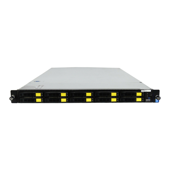
- Page 31 3.5” HDD S BOUT THE ERVER YSTEM 2.5” HDD System Front Features Figure 1-4. 2.5” HDD System Front Features 2.5” HDD System Front Panel Definition 2.5” HDD System Front Control Panel Table 1-6: 2.5” HDD Front Panel Definition ESCRIPTION Control Panel Connect USB devices to these ports HDD Bays Insert HDDs here.
- Page 32 3.5” HDD S BOUT THE ERVER YSTEM Table 1-7: 2.5” HDD LED Function and Behavior ESCRIPTION Amber Blinking Critical failure: fan, voltage, temperature state Non-critial failure: fan, voltage, Event LED temperature state, CPU, thermal trip SEL cleared, DC Off, last pending warning/error de-asserted Green ON, link LAN1/2 LED...
-
Page 33: System Hdd Introduction
HDD I BOUT THE ERVER YSTEM NTRODUCTION System HDD Introduction This system is available in two form factors, 2.5” HDD and 3.5” HDD. 2.5” Hard Disk Drive Configuration HDD 0 HDD 2 HDD 4 HDD 6 HDD 8 HDD 1 HDD 3 HDD 5 HDD 7... -
Page 34: System Rear Features
BOUT THE ERVER YSTEM EATURES System Rear Features System Rear View Figure 1-8. I/O Features (shown with ports on Mezzanine card) Table 1-8: System I/O Features (Continued) Table 1-8: System I/O Features EATURE ESCRIPTION EATURE ESCRIPTION Dedicated Management LAN Connect this to a network 10GbE SFP+ Port Optional Port... -
Page 35: System I/O Led Description
BOUT THE ERVER YSTEM EATURES System I/O LED Description Rear I/O LED Description Table 1-9: Rear side LED Function and Behavior (1G LAN) OLOR ONDITION ESCRIPTION Unit selected for identification Identification LED Blue No identification requested LAN Link Link/Act Green Blinking LAN access (off when there is traffic) Disconnect... - Page 36 BOUT THE ERVER YSTEM EATURES Table 1-9: Rear side LED Function and Behavior (1G LAN) (Continued) OLOR ONDITION ESCRIPTION LAN Link Link/Act Green Blinking LAN access (off when there is traffic) Service Port (LAN 3) LED Disconnect Speed Green Link speed is 10/100/1000Mbits/sec Table 1-10: Rear side LED Function and Behavior (10G LAN) OLOR ONDITION...
- Page 37 BOUT THE ERVER YSTEM EATURES Table 1-10: Rear side LED Function and Behavior (10G LAN) (Continued) OLOR ONDITION ESCRIPTION LAN Link LAN access (off when there Link/Act Green Blinking is traffic) Disconnect LAN2 LED (Left) Blue Link speed is 10Gbits/sec Amber Link speed is 1Gbits/sec Speed...
- Page 38 Installing Hardware Installing Hardware Chapter 2 Chapter 2...
-
Page 39: Safety Measures
NSTALLING ARDWARE AFETY EASURES 2.1 Safety Measures WARNING! WARNING! Always ask for assistance to move or lift the system. Wear a grounded wrist strap. If none are available, discharge any personal static electricity by touching the bare metal chassis of the server case, or the bare metal body of any other grounded device. -
Page 40: Top Cover
NSTALLING ARDWARE OVER 2.2 Top Cover Opening the Top Cover 4. Lift the top cover off the chassis. 1. Turn off the system and any attached peripherals. 2. Unplug the AC power cables and disconnect all peripherals, LAN lines and any other cables. ... -
Page 41: Closing The Top Cover
NSTALLING ARDWARE LOSING THE OVER Closing the Top Cover 1. Place the top cover on the chassis. 2. Slide the top cover toward the HDDs. Figure 2-2. Closing the Top Cover... -
Page 42: Hard Disk Drives
NSTALLING ARDWARE RIVES 2.3 Hard Disk Drives The following procedures demonstrate installation and removal of 2.5 and 3.5 inch hard drives. WARNING! Repairs should be perfomed by a certified service technician. Damage to the system or components due to unauthorized servicing is not covered by the warranty agreement. -
Page 43: Installing A 2.5" Hard Drive
2.5” H NSTALLING ARDWARE NSTALLING A RIVE Installing a 2.5” Hard Drive 4. Remove the four (4) screws securing the hard drive to the HDD tray. 1. Align the 2.5” hard drive tray with the new hard drive and secure with the four (4) screws Figure 2-5. -
Page 44: Removing A 3.5" Hard Drive
3.5” H NSTALLING ARDWARE EMOVING A RIVE Removing a 3.5” Hard Drive 1. Press the tray handle button. Figure 2-7. Installing a 2.5” HDD in the System WARNING! Do not force the tray handle closed. If resistance is encountered check the hard drive is properly inserted and the Figure 2-8. -
Page 45: Installing A 3.5" Hard Drive
3.5” H NSTALLING ARDWARE NSTALLING A RIVE Installing a 3.5” Hard Drive WARNING! Make sure the hard drive tray handle is in the fully open position. 1. Align the 3.5” hard drive tray with the new hard drive and 3. Remove the tray from the system. secure with the four (4) screws 4. - Page 46 3.5” H NSTALLING ARDWARE NSTALLING A RIVE 2. Align the tray assembly with the HDD bay and insert the HDD until it is fully seated in the bay. Figure 2-12. Installing a 3.5” Hard Drive WARNING! Do not force the tray handle closed. If resistance is encountered, check the hard drive is properly inserted and the hard drives on either side are properly inserted.
-
Page 47: Power Supply Unit
NSTALLING ARDWARE OWER UPPLY 2.4 Power Supply Unit The system supports both single and redundant power supplies 2. Press and hold the locking latch lever. as shown in the following illustrations. CAUTION! DISCONNECT THE POWER SUPPLY UNIT FROM THE POWER SOURCE BEFORE REMOVING PSU AILURE TO DO SO COULD RESULT IN DAMAGE TO THE EQUIPMENT OR PERSONAL INJURY... -
Page 48: Installing A Power Supply Unit
NSTALLING ARDWARE NSTALLING A OWER UPPLY Installing a Power Supply Unit CAUTION! O NOT MOVE THE SYSTEM BY HANDLING THE SLIDE LEVER ON MODULE TO PREVENT DAMAGE TO THE SYSTEM OR THE MODULE Insert the power supply unit (PSU) into the system. Figure 2-15. -
Page 49: Mainboard Module
NSTALLING ARDWARE AINBOARD ODULE 2.5 Mainboard Module Removing a Mainboard Module 2. Lift the front end of the mainboard until free of the chassis guide pin. Prerequisite: Prerequisite: Remove the top cover. See Opening the Top Cover on page 2-2. Disconnect all cables from mainboard. -
Page 50: Installing A Mainboard Module
NSTALLING ARDWARE NSTALLING A AINBOARD ODULE Installing a Mainboard Module 3. Lift mainboard in an angle to release the connectors from the slots on rear panel. Prerequisite: Prerequisite: Port Openings Remove the top cover. See Opening the Top Cover on page 2-2. - Page 51 NSTALLING ARDWARE NSTALLING A AINBOARD ODULE 5. Secure eight (8) screws to the mainboard. Figure 2-19. Removing the Mainboard Module Screws 2-13...
-
Page 52: Processor Heat Sinks
NSTALLING ARDWARE ROCESSOR INKS 2.6 Processor Heat Sinks Removing a Heat Sink 1. In a sequential order, loosen the four captive screws securing the heat sink to the mainboard. WARNING! The heat sink remains hot after the system has been powered down. -
Page 53: Installing A Heat Sink
NSTALLING ARDWARE NSTALLING A Installing a Heat Sink Prerequisite: Prerequisite: Remove the top cover. See Opening the Top Cover on page 2-2 Important: Tighten the captive screws in the sequence indicated in the illustration. 1. Align the heat sink. Make sure the airflow sticker points to the rear of the chassis. -
Page 54: Processors
NSTALLING ARDWARE ROCESSORS 2.7 Processors Removing a Processor WARNING! The processor remains hot after the system has been powered down. Allow sufficient time to cool before handling system components. Prerequisite: Prerequisite: Remove the top cover. See Opening the Top Cover on page 2-2. - Page 55 NSTALLING ARDWARE EMOVING A ROCESSOR 3. Press down on the right processor locking lever to lift the processor cover part way and then lift the processor load plate to the fully open position. Figure 2-23. Releasing the Left Processor Locking Lever CAUTION! THE LOCKING LEVER IS HELD UNDER CONSIDERABLE FORCE AND MAY SPRING UP UNEXPECTEDLY...
-
Page 56: Installing A Processor
NSTALLING ARDWARE NSTALLING A ROCESSOR Installing a Processor Prerequisite: Prerequisite: Remove the top cover. See Opening the Top Cover on page 2-2. Remove the CPU heat sink. See Removing a Heat Sink on page 2-14. 1. Align the gold triangle identifying pin 1 of the processor with the triangular cutout of the processor, and the four (4) indents on processor with the four (4) tabs on socket. - Page 57 NSTALLING ARDWARE NSTALLING A ROCESSOR 2. Insert the processor into the socket, ensuring the four keys on the socket fit into the corresponding keys on the processor. WARNING! The processor should fit easily into the socket. Do not force the processor in place. 3.
-
Page 58: Memory Modules
NSTALLING ARDWARE EMORY ODULES 2.8 Memory Modules WARNING! The mainboards are supplied with all DIMM slots populated with memory 9 dummies for proper air flow. When installing and replacing memory modules, only remove those dummies that are to be directly replaced. All DIMM slots must be occupied at all times by either a memory module or dummy cover. -
Page 59: Installing A Memory Module
NSTALLING ARDWARE NSTALLING A EMORY ODULE Installing a Memory Module Prerequisite: Prerequisite: Remove the top cover. See Opening the Top Cover on Slot lever page 2-2. CAUTION! HANDLE THE MEMORY MODULE BY THE EDGES AT ALL TIMES Figure 2-28. -
Page 60: Memory Population Rules
NSTALLING ARDWARE EMORY OPULATION ULES Memory Population Rules CPU 0 C-D DIMM D2 CPU 1 C-F DIMM F2 CPU 0 C-D DIMM D1 CPU 1 C-F DIMM F1 CPU 0 C-D DIMM D0 CPU 1 C-F DIMM F0 CPU 0 C-C DIMM C2 CPU 1 C-E DIMM E2 CPU 0 C-C DIMM C1 CPU 1 C-E DIMM E1... - Page 61 NSTALLING ARDWARE EMORY OPULATION ULES Table 2-1: RDIMM Support (Reduced Length) ANKS MEMORY ) & ) & SPEED VOLTAGE VALIDATED FOR HORT ENGTH BY SLOT PER CHANNEL DIMM & CAPACITY PER DIMM 2,3* PER CHANNEL DATA (GB) DIMM WIDTH 1 Slot per 2 Slots per Channel 3 Slots per Channel Channel...
- Page 62 NSTALLING ARDWARE EMORY OPULATION ULES Important: Note: a*: Supported but not validated. 1*: Supported DRAM densities are 1Gb, 2Gb, and 4 Gb. Only 2 Gb and 4 Gb are validated by Intel. b*: Supported and validated. c*: Supported with limited validation 2*: Command Address Timing is 1N.
-
Page 63: Pcie Riser Assembly
NSTALLING ARDWARE ISER SSEMBLY 2.9 PCIe Riser Assembly Removing the PCIe Riser Assembly 2. Pull the assembly out of the chassis. Prerequisite: Prerequisite: Remove the top cover. See Opening the Top Cover on page 2-2. 1. Remove one (1) screw from the chassis. Figure 2-32. -
Page 64: Installing The Pcie Riser Assembly
NSTALLING ARDWARE NSTALLING THE ISER SSEMBLY Installing the PCIe Riser Assembly 3. Secure the assembly to the chassis with one (1) screw. Prerequisite: Prerequisite: Remove the top cover. See Opening the Top Cover on page 2-2. 1. Align the assembly with the guide pin hole in the chassis. Figure 2-34. -
Page 65: Pcie Expansion Card
NSTALLING ARDWARE XPANSION 2.10 PCIe Expansion Card Removing the PCIe Expansion Card 2. Disconnect the PCIe expansion card from the riser. Prerequisite: Prerequisite: Remove the top cover. See Opening the Top Cover on page 2-2. Remove the PCIe riser assembly. See Removing the PCIe Riser Assembly on page 2-25. -
Page 66: Installing The Pcie Expansion Card
NSTALLING ARDWARE NSTALLING THE XPANSION Installing the PCIe Expansion Card 3. Secure the PCIe card to the riser with one (1) screw. Prerequisite: Prerequisite: Remove the PCIe riser assembly. See Removing the PCIe Riser Assembly on page 2-25 1. Align the PCIe expansion card with the connector on riser. -
Page 67: Mezzanine Card
NSTALLING ARDWARE EZZANINE 2.11 Mezzanine Card Installing a LAN Mezzanine Card 3. Insert the linking board into the module connector. Prerequisite: Prerequisite: Remove the PCIe riser assembly. See Removing the PCIe Riser Assembly on page 2-25. 1. Align the module with the screw holes on the module sup- port plate. - Page 68 LAN M NSTALLING ARDWARE NSTALLING A EZZANINE 4. Remove the screw securing the dummy bracket to the 6. Align the linking board with the mainboard connector. chassis. Figure 2-41. Dummy Bracket 5. Remove the dummy bracket from the chassis. Figure 2-42. Linking Board and Mainboard Connector 7.
-
Page 69: Removing A Lan Mezzanine Card
LAN M NSTALLING ARDWARE EMOVING A EZZANINE Removing a LAN Mezzanine Card 8. Secure the module assembly to the chassis with one (1) screw. Prerequisite: Prerequisite: Remove the top cover. See Opening the Top Cover on page 2-2. Remove the PCIe riser assembly. See Removing the PCIe Riser Assembly on page 2-25. - Page 70 LAN M NSTALLING ARDWARE EMOVING A EZZANINE 2. Disconnect the module linking board from the mainboard 4. Disconnect the linking board from the module connector. connector. Top View Top View Bottom View Figure 2-46. Linking Board and Module Connector Bottom View Figure 2-45.
-
Page 71: Installing A Sas 6G Mezzanine Card
SAS 6G M NSTALLING ARDWARE NSTALLING A EZZANINE Installing a SAS 6G Mezzanine Card 5. Remove the four (4) screws from the module support plate. Prerequisite: Prerequisite: Remove the top cover. See Opening the Top Cover on page 2-2. Remove the PCIe riser assembly. See Removing the PCIe Riser Assembly on page 2-25. - Page 72 SAS 6G M NSTALLING ARDWARE NSTALLING A EZZANINE 1. Align the module with the screw holes on the module sup- 3. Connect the linking board to the module connector. port plate. Figure 2-49. 6G Linking Board and Module Connector Figure 2-48. 6G Module Screws 2.
- Page 73 SAS 6G M NSTALLING ARDWARE NSTALLING A EZZANINE 4. Remove nine (9) memory modules. 7. Align the linking board with the mainboard connector. 5. Connect the SAS cables to the ports on the module. Figure 2-51. 6G Linking Board and Mainboard Connector Figure 2-50.
- Page 74 SAS 6G M NSTALLING ARDWARE NSTALLING A EZZANINE 9. Secure the module assembly to the chassis with two (2) 10.Route the SAS cables along the side of the chassis. screws. Cables Expander Board Connectors Figure 2-52. 6G Module Assembly Screws Figure 2-53.
-
Page 75: Removing A Sas 6Gb Mezzanine Card
SAS 6G NSTALLING ARDWARE EMOVING A EZZANINE Removing a SAS 6Gb Mezzanine 1. Disconnect the SAS cables from the connectors on the expander board. Card Prerequisite: Prerequisite: Remove the top cover. See Opening the Top Cover on page 2-2. Remove the PCIe riser assembly. See Removing the PCIe Riser Assembly on page 2-25. - Page 76 SAS 6G NSTALLING ARDWARE EMOVING A EZZANINE 3. Remove two (2) screws securing the module assembly to 4. Disconnect the module linking board from the mainboard the chassis. connector. Figure 2-55. 6G Module Assembly Screws Figure 2-56. 6G Module Linking Board 2-38...
- Page 77 SAS 6G NSTALLING ARDWARE EMOVING A EZZANINE 5. Remove the module assembly from the chassis. 7. Disconnect the linking board from the module connector. Figure 2-58. 6G Linking Board and Module Connector Figure 2-57. 6G Module Assembly and SAS Cables 6.
- Page 78 SAS 6G NSTALLING ARDWARE EMOVING A EZZANINE 8. Remove the four (4) screws from the module support plate. Figure 2-59. 6G Module Screws and Support Plate 9. Remove the module from the support plate. 2-40...
-
Page 79: Intelligent Battery Backup Unit
NSTALLING ARDWARE NTELLIGENT ATTERY ACKUP 2.12. Intelligent Battery Backup Unit A single iBBU provides backup functionality for a single module. To provide backup functionality for all four modules, each module must have an iBBU installed. Installing an iBBU 3. Align the bracket and iBBU assembly. Prerequisite: Prerequisite: Remove the top cover. -
Page 80: Removing An Ibbu
NSTALLING ARDWARE EMOVING AN I Removing an iBBU 5. Secure the iBBU bracket to the chassis with screw(s). Prerequisite: Prerequisite: Remove the top cover. See Opening the Top Cover on page 2-2. 1. Disconnect the iBBU cable from the card. 2. - Page 81 NSTALLING ARDWARE EMOVING AN I 5. Remove screw(s) securing the bracket to the iBBU assembly. Figure 2-64. Removing iBBU Assembly from Bracket 6. Remove assembly from the bracket. 2-43...
-
Page 82: Air Duct
NSTALLING ARDWARE 2.13 Air Duct Removing the Air Duct Installing the Air Duct Prerequisite: Prerequisite: Prerequisite: Prerequisite: Remove the top cover. See Opening the Top Cover on Remove the top cover. See Opening the Top Cover on page 2-2. page 2-2 Remove the air duct from the chassis. -
Page 83: Fan Module Assembly
NSTALLING ARDWARE ODULE SSEMBLY 2.14 Fan Module Assembly Removing Fan Module Assembly 2. Remove four (4) screws securing the fan module assem- bly to the chassis. Prerequisite: Prerequisite: Remove the top cover. See Opening the Top Cover on page 2-2. 1. -
Page 84: Installing Fan Module Assembly
NSTALLING ARDWARE NSTALLING ODULE SSEMBLY Installing Fan Module Assembly Prerequisite: Prerequisite: 4. Connect six (6) fan module cables to the connectors on the HDD backplane. Remove the top cover. See Opening the Top Cover on page 2-2 1. Align the fan module assembly with the screw holes on the chassis. -
Page 85: Expander Backplane
NSTALLING ARDWARE XPANDER ACKPLANE 2.15 Expander Backplane Removing the Expander Backplane k. System FAN 0 l. Jumper setting for expander operation mode. Prerequisite: Prerequisite: m. IPMB connector linking to on-board BMC controller Remove the top cover. See Opening the Top Cover on (Fan speed). - Page 86 NSTALLING ARDWARE EMOVING THE XPANDER ACKPLANE Figure 2-71. Expander BP Connectors 2. Remove four (4) screws from the HDD expander board. Figure 2-72. Removing the Expander Backplane Screws 2-48...
-
Page 87: Installing The Expander Backplane
NSTALLING ARDWARE NSTALLING THE XPANDER ACKPLANE Installing the Expander Backplane 3. Slide the expander BP toward the rear of the chassis until the B2B Connectors (a, b & c) are free from the HDD BP. Prerequisite: Prerequisite: Remove the top cover. See Opening the Top Cover on HDD Backplane page 2-2 1. - Page 88 NSTALLING ARDWARE NSTALLING THE XPANDER ACKPLANE 3. Slide the expander BP toward the front of the chassis until d. 10 pin Power connector for BP with +12V, +5V, the B2B connectors (a, b & c) are connected to the HDD +3.3V,GND e.
- Page 89 NSTALLING ARDWARE NSTALLING THE XPANDER ACKPLANE Figure 2-76. Expander BP Connectors 2-51...
-
Page 90: Hdd Backplane
HDD B NSTALLING ARDWARE ACKPLANE 2.16 HDD Backplane Removing the HDD Backplane (2.5” 3. Remove the backplane from the chassis. HDD w Expander SKU) Prerequisite: Prerequisite: Remove the HDDs. See Removing a 2.5” Hard Drive on page 2-4. Remove the top cover. See Opening the Top Cover on page 2-2. -
Page 91: Installing The Hdd Backplane (2.5" Hdd W Expander Sku)
HDD B (2.5” HDD SKU) NSTALLING ARDWARE NSTALLING THE ACKPLANE XPANDER Installing the HDD Backplane (2.5” 1. Align the HDD backplane with the screw holes in the chassis. HDD w Expander SKU) Prerequisite: Prerequisite: Remove the HDDs. See Removing a 2.5” Hard Drive on page 2-4. - Page 92 HDD B (2.5” HDD SKU) NSTALLING ARDWARE NSTALLING THE ACKPLANE XPANDER 2. Secure the HDD Backplane to the chassis with six (6) 3. Connect the power cable to the 10 Pin Power connector screws. on the HDD BP. Power Connector Figure 2-80.
-
Page 93: Removing The Hdd Backplane (2.5" Hdd W/O Expander Sku)
HDD B (2.5” HDD SKU) NSTALLING ARDWARE EMOVING THE ACKPLANE XPANDER Removing the HDD Backplane (2.5” e. Golden finger for LED signals to 1 to 1 HDD BP B2B connector. HDD w/o Expander SKU) f. Winbond W83793 for FAN control Prerequisite: Prerequisite: g. - Page 94 HDD B (2.5” HDD SKU) NSTALLING ARDWARE EMOVING THE ACKPLANE XPANDER 2. Remove four (4) screws from the 1:1 backplane. 3. Slide the 1:1 BP toward the rear of the chassis until the B2B Connector is free from the HDD BP. B2B Connector Chassis Pins Figure 2-82.
- Page 95 HDD B (2.5” HDD SKU) NSTALLING ARDWARE EMOVING THE ACKPLANE XPANDER 6. Disconnect the 10 Pin Power connector power cable from 7. Remove six (6) screws from the HDD backplane. the HDD BP. Power Connector Figure 2-84. HDD Backplane Connectors Figure 2-85.
-
Page 96: Installing The Hdd Backplane (2.5" Hdd W/O Expander Sku)
HDD B (2.5” HDD SKU) NSTALLING ARDWARE NSTALLING THE ACKPLANE XPANDER Installing the HDD Backplane (2.5” 8. Remove the backplane from the chassis. HDD w/o Expander SKU) Prerequisite: Prerequisite: Remove the HDDs. See Removing a 2.5” Hard Drive on page 2-4. Remove the top cover. - Page 97 HDD B (2.5” HDD SKU) NSTALLING ARDWARE NSTALLING THE ACKPLANE XPANDER 2. Secure the HDD Backplane to the chassis with six (6) 3. Align the holes in the 1:1 BP with the chassis pins. screws. Figure 2-89. Aligning the 1:1 Backplane Figure 2-88.
- Page 98 HDD B (2.5” HDD SKU) NSTALLING ARDWARE NSTALLING THE ACKPLANE XPANDER 5. Slide the 1:1 BP toward the front of the chassis until the 6. Secure the 1:1 BP to the chassis with four (4) screws. B2B Connector is connected to the HDD BP. B2B Connector Figure 2-91.
- Page 99 HDD B (2.5” HDD SKU) NSTALLING ARDWARE NSTALLING THE ACKPLANE XPANDER c. SGPIO connector 2 for HDD 4 ~ 7. i. AMI 9086 LED control mode setting jumper. d. SGPIO connector 1 for HDD 0 ~ 3. j. System FAN 0 for CPU 0 Block e.
-
Page 100: Removing The Hdd Backplane (3.5" Hdd Sku)
HDD B (3.5” HDD SKU) NSTALLING ARDWARE EMOVING THE ACKPLANE Removing the HDD Backplane (3.5” d. Device 3 Connector connect to HDD 3 HDD SKU) e. 10 pin Power connector for BP with +12V, +5V, +3.3V f. IPMB connector lining to on board BMC to control FAN Prerequisite: Prerequisite: Speed... - Page 101 HDD B (3.5” HDD SKU) NSTALLING ARDWARE EMOVING THE ACKPLANE 2. Remove five (5) screws from the HDD backplane. 3. Remove the HDD backplane from the chassis. Figure 2-94. Removing the 3.5” HDD Backplane Screws Figure 2-95. Removing the 3.5” HDD Backplane 2-63...
-
Page 102: Installing The Hdd Backplane (3.5" Hdd Sku)
HDD B (3.5” HDD SKU) NSTALLING ARDWARE NSTALLING THE ACKPLANE Installing the HDD Backplane (3.5” 2. Secure the HDD Backplane to the chassis with five (5) screws. HDD SKU) Prerequisite: Prerequisite: Remove the HDDs. See Removing a 3.5” Hard Drive on page 2-6. - Page 103 HDD B (3.5” HDD SKU) NSTALLING ARDWARE NSTALLING THE ACKPLANE f. IPMB connector lining to on board BMC to control FAN j. System FAN 2 for CPU 0 Block Speed k. System FAN 3 for CPU 1 Block g. SGPIO connector for HDD LED Decode. l.
-
Page 104: Bios
BIOS BIOS Chapter 3 Chapter 3... -
Page 105: Bios Setup Utility
BIOS BIOS S ETUP TILITY 3.1 BIOS Setup Utility The BIOS Setup utility is provided to perform system configura- tionality. The following table lists and describes each functional tion changes and to display current settings and environment area. information. Table 3-1: BIOS Setup Page Layout The BIOS Setup utility stores configuration settings in system UNCTIONAL ESCRIPTION... -
Page 106: Entering Bios Setup
BIOS BIOS S NTERING ETUP Entering BIOS Setup Table 3-2: BIOS Setup: Keyboard Command PTION ESCRIPTION BIOS Setup is started by pressing <DEL> or <F2> during boot time when the OEM logo is displayed. The <Enter> key is used to activate sub-menus when the selected feature is a sub-menu, or to display a pick list if a selected option has a When Quiet Boot is disabled, the message "press <DEL>... - Page 107 BIOS EYBOARD OMMANDS Table 3-2: BIOS Setup: Keyboard Command (Continued) Table 3-2: BIOS Setup: Keyboard Command (Continued) PTION ESCRIPTION PTION ESCRIPTION The up arrow is used to select the previous Pressing <F8> makes the following message to Select value in a pick list, or the previous option in a appear: Item menu item's option list.
-
Page 108: Menu Selection Bar
BIOS ELECTION Table 3-2: BIOS Setup: Keyboard Command (Continued) The text and values in the Setup Item, Options, and Help columns in the tables are displayed on the BIOS Setup PTION ESCRIPTION screens. Pressing <F10> makes the following message Bold text in the Options column of the tables indicates ... -
Page 109: Main Screen
BIOS CREEN Main Screen Table 3-3: Main Screen Fields ETUP PTIONS OMMENTS The Main screen is the screen that is first displayed when BIOS Setup is entered, unless an error has occurred. If an error has Information only. BIOS Vendor Displays the BIOS occurred, the Error Manager screen will be displayed instead. -
Page 110: Advanced Screen
BIOS DVANCED CREEN Advanced Screen Table 3-3: Main Screen Fields (Continued) ETUP PTIONS OMMENTS The Advanced screen provides an access point to configure Information only. several options. On this screen, the user selects the option that Access Level Displays the Access is to be configured. - Page 111 BIOS DVANCED CREEN Table 3-4: Advanced Screen Fields (Continued) Table 3-4: Advanced Screen Fields ETUP PTIONS OMMENTS ETUP PTIONS OMMENTS Super IO System Super IO PCI, PCI-X and PCI Subsystem Configuration Chip Parameters. PCI Express Settings Settings. Onboard Device Onboard Device Configuration Parameters Trusted...
-
Page 112: Pci Screen
BIOS DVANCED CREEN PCI Screen Table 3-5: PCI Subsystem Settings Screen Fields ETUP PTIONS OMMENTS The PCI Screen provides fields to configure PCI add-in cards, the onboard NIC controllers, and video options. To access this Change PCI PCI Express Express Devices screen from the Main screen, select Advanced | PCI. - Page 113 BIOS DVANCED CREEN PCI Express Settings Screen Table 3-6: PCI Express Settings Fields ETUP PTIONS OMMENTS Aptio Setup Utility - Copyright (C) 2011 American Megatrends, Inc. Main Advanced Chipset Server Mgmt Boot Security Save & Exit [Auto] Set Maximum PCI Express Device Settings Set Maximum Payload of PCI [128 Bytes] Maximum Payload...
- Page 114 BIOS DVANCED CREEN Trusted Computing Screen Table 3-7: Trusted Computing Screen Fields ETUP PTIONS OMMENTS Enables or Disables BIOS support for security device. Security [Disabled] O.S. will not show Device Security Device. [Enabled] Support TCG EFI protocol and INT1A interface will not be available.
- Page 115 BIOS DVANCED CREEN WHEA Screen Table 3-8: WHEA Configuration Fields ETUP PTIONS OMMENTS Aptio Setup Utility - Copyright (C) 2011 American Megatrends, Inc. Main Advanced Chipset Server Mgmt Boot Security Save & Exit Enable or disable Windows WHEA Support [Enabled] Enable or disable Windows Hardware Error Architecture.
-
Page 116: Processor Configuration Screen
BIOS DVANCED CREEN Processor Configuration Screen Table 3-9: Processor Configuration Fields Options ETUP OMMENTS The Processor screen provides a place for the user to view the processor core frequency, system bus frequency, and enable or Socket 0 CPU Socket specific Information CPU Information. - Page 117 BIOS DVANCED CREEN Table 3-9: Processor Configuration Fields (Continued) Table 3-9: Processor Configuration Fields (Continued) Options Options ETUP OMMENTS ETUP OMMENTS [All] Enable prefetcher of next L1 Data [Disabled] DCU Streamer line based upon Prefetcher Number of cores [Enabled] multiple loads in Active to enable in each same cache line.
- Page 118 BIOS DVANCED CREEN Socket 0 CPU Information Screen Table 3-10: Socket 0 CPU Information Fields (Continued) ETUP PTIONS OMMENTS Aptio Setup Utility - Copyright (C) 2011 American Megatrends, Inc. Main Advanced Chipset Server Mgmt Boot Security Save & Exit Information only. Max CPU Displays the Max Socket 0 CPU Information...
- Page 119 BIOS DVANCED CREEN CPU Power Management Configuration Screen Table 3-10: Socket 0 CPU Information Fields (Continued) ETUP PTIONS OMMENTS Aptio Setup Utility - Copyright (C) 2011 American Megatrends, Inc. Main Advanced Chipset Server Mgmt Boot Security Save & Exit Information only. L3 Cache Displays the size CPU Power Management Configuration...
- Page 120 BIOS DVANCED CREEN Table 3-11: CPU Power Mgmt Configuration Fields (Continued) Table 3-11: CPU Power Mgmt Configuration Fields (Continued) ETUP PTIONS OMMENTS ETUP PTIONS OMMENTS Only appears Long duration Long duration [Disabled] Enable/Disable when Power power limit in EIST power limit Intel SpeedStep.
-
Page 121: Runtime Error Logging Screen
BIOS DVANCED CREEN Runtime Error Logging Screen Table 3-12: Runtime Error Logging Fields (Continued) ETUP PTIONS OMMENTS Aptio Setup Utility - Copyright (C) 2011 American Megatrends, Inc. Enter the Main Advanced Chipset Server Mgmt Boot Security Save & Exit Memory Corr. Memory Runtime Error Logging Support [Enabled]... -
Page 122: Sata Controller Screen
BIOS DVANCED CREEN SATA Controller Screen Table 3-13: ATA Controller Configuration Fields ETUP PTIONS OMMENTS The ATA Controller screen provides fields to configure SATA hard disk drives. It also provides information on the hard disk [Disabled] Select SATA (1) AHCI Mode. drives that are installed. -
Page 123: Sas Configuration Screen
BIOS DVANCED CREEN SAS Configuration Screen Table 3-14: SAS Configuration Fields (Continued) ETUP PTIONS OMMENTS BIOS will display device information only when user select Intel RSTe OPROM. Information only. Displays SAS Port 1 the device on SAS Port 1. Information only. Displays Aptio Setup Utility - Copyright (C) 2011 American Megatrends, Inc. -
Page 124: Intel Txt(Lt-Sx) Screen
BIOS DVANCED CREEN Intel TXT(LT-SX) Screen Table 3-15: Intel TXT (LT-SX) Configuration Fields (Continued) ETUP PTIONS OMMENTS Aptio Setup Utility - Copyright (C) 2011 American Megatrends, Inc. Information only. Main Advanced Chipset Server Mgmt Boot Security Save & Exit Chipset: TXT Displays the Intel TXT(LT-SX) Hardware Support Feature... -
Page 125: Usb Configuration Screen
BIOS DVANCED CREEN USB Configuration Screen Table 3-15: Intel TXT (LT-SX) Configuration Fields (Continued) ETUP PTIONS OMMENTS The USB Configuration screen provides fields to configure the Information only. USB controller options. CPU: TXT Displays the Feature CPU: TXT To access this screen from the Main screen, select Advanced | Feature USB Configuration. -
Page 126: Super I/O Configuration Screen
BIOS DVANCED CREEN Super I/O Configuration Screen Table 3-16: USB Configuration Fields ETUP PTIONS OMMENTS The Serial Ports screen provides fields to configure the Serial Port [COM Port]. Information only. Display all of the USB Devices: USB devices To access this screen from the Main screen, select Advanced | attached. - Page 127 BIOS DVANCED CREEN Serial Port 0 Configuration Screen Table 3-17: Super I/O Configuration Fields ETUP PTIONS OMMENTS Aptio Setup Utility - Copyright (C) 2011 American Megatrends, Inc. Main Advanced Chipset Server Mgmt Boot Security Save & Exit Information only. Super IO Chip Display Super IO Serial Port 0 Configuration Enable or Disable Serial Port...
-
Page 128: Onboard Device Configuration Screen
BIOS DVANCED CREEN Onboard Device Configuration Screen Table 3-19: Onboard Device Configuration Fields ETUP PTIONS OMMENTS [Disabled] [Enabled With PXE] Enable or Disable Onboard LAN Onboard LAN [Enabled port 1 port 1. Without PXE] [iSCSI Remote Boot] [Disabled] [Enabled With PXE] Enable or Disable Onboard LAN Onboard LAN... -
Page 129: Console Redirection Screen
BIOS DVANCED CREEN Console Redirection Screen Table 3-20: Console Redirection Fields (Continued) ETUP PTIONS OMMENTS Aptio Setup Utility - Copyright (C) 2011 American Megatrends, Inc. The settings Main Advanced Chipset Server Mgmt Boot Security Save & Exit specify how the Console Redirection Enable or host computer COM0... -
Page 130: Console Redirection Settings
BIOS DVANCED CREEN Console Redirection Settings Table 3-21: Console Redirection Settings Fields ETUP PTIONS OMMENTS Aptio Setup Utility - Copyright (C) 2011 American Megatrends, Inc. Main Advanced Chipset Server Mgmt Boot Security Save & Exit Emulation: ANSI: Extended ASCII char COM0 Emulation: ANSI: Extended Console Redirection Settings... - Page 131 BIOS DVANCED CREEN Table 3-21: Console Redirection Settings Fields (Continued) Table 3-21: Console Redirection Settings Fields (Continued) ETUP PTIONS OMMENTS ETUP PTIONS OMMENTS A parity bit can be sent Flow control can with the data bits to prevent data loss from detect some buffer overflow.
-
Page 132: Iscsi Configuration
BIOS DVANCED CREEN iSCSI Configuration Table 3-22: Console Redirection Fields (Continued) ETUP PTIONS OMMENTS Delete one or Delete Attempts more attempts. Change the order of Attempts using +/- keys, Use arrow keys to Change Attempt select the attempt Order then press +/- to move the attempt up/down in the attempt oder list. - Page 133 BIOS DVANCED CREEN Add an Attempt Figure 3-21. Figure 3-22. Add an Attempt Screen Table 3-23: Table 3-24: Console Redirection Settings Fields ETUP PTIONS OMMENTS ETUP PTIONS OMMENTS iSCSI Attempt The human name address Name defined for this attempt. and BUS/ PFA: BUSx | Devx | xx:xx:xx:xx:xx: Dev/Func...
- Page 134 BIOS DVANCED CREEN Table 3-24: Console Redirection Settings Fields (Continued) Table 3-24: Console Redirection Settings Fields (Continued) ETUP PTIONS OMMENTS ETUP PTIONS OMMENTS Initiator IP address is [Disabled] Enable DHCP Enable DHCP system assigned in IP6 [Enabled] IP4] mode. In Autoconfigure Initiator IP Enter IP address in mode, iSCSI driver will...
- Page 135 BIOS DVANCED CREEN Table 3-24: Console Redirection Settings Fields (Continued) ETUP PTIONS OMMENTS CHAP Name CHAP Name The minimum length is 12 bytes and the CHAP Secret maximum length is 16 bytes. Must reboot system Save Changes manually for changes to take place.
-
Page 136: Chipset Screen
BIOS HIPSET CREEN Chipset Screen Table 3-26: Chipset Fields ETUP PTIONS OMMENTS The Chipset screen provides an access point to configure sev- eral options. On this screen, the user selects the option that is North Bridge North Bridge Parameters. to be configured. Configurations are performed on the selected screen, not directly on the Chipset screen. -
Page 137: North Bridge Screen
BIOS HIPSET CREEN North Bridge Screen Table 3-27: North Bridge Configuration Fields (Continued) ETUP PTIONS OMMENTS Information only. Current Displays the Memory Mode Current Memory Mode. Information only. Current Displays the Memory Current Memory Speed Speed. Information only. Displays the Mirroring Miorring support state. - Page 138 BIOS HIPSET CREEN Intel(R) VT-d Screen Table 3-27: North Bridge Configuration Fields (Continued) ETUP PTIONS OMMENTS Enable or [Disabled] Disable Non NUMA uniform Memory [Enabled] Access (NUMA). [Disabled] Enable/Disable Patrol Scrub Patrol Scrub [Enabled] Enable/Disable [Disabled] Demand Demand Scrub Scrubing [Enabled] Feature Enable/Disable...
-
Page 139: South Bridge Configuration Screen
BIOS HIPSET CREEN South Bridge Configuration Screen Table 3-28: Intel(R) VT-d Fields (Continued) ETUP PTIONS OMMENTS Aptio Setup Utility - Copyright (C) 2011 American Megatrends, Inc. Enable/Disable Main Advanced Chipset Server Mgmt Boot Security Save & Exit [Disabled] Coherency VT-d Engine Enable/Disable Patsburg Support Coherency... -
Page 140: Usb Configuration
BIOS HIPSET CREEN USB Configuration Table 3-29: South Bridge Configuration Fields (Continued) ETUP PTIONS OMMENTS Enabled/Disabled onboard SAS [Disabled] Onboard SAS option rom if Oprom Launch Storage [Enabled] OpROM is enabled. Enabled/Disabled onboard SATA Onboard [Disabled] RAID option rom SATA RAID if Launch Storage [Enabled] Oprom... -
Page 141: Me Subsystem Screen
BIOS HIPSET CREEN ME Subsystem Screen Table 3-30: USB Configuration Fields (Continued) ETUP PTIONS OMMENTS Disable the EHCI Enabled/Disabled EHCI [Disabled] Controller would USB EHCI Controller 1 [Enabled] disable all USB Controller 1. ports from it. Disable the EHCI Enabled/Disabled Controller would EHCI [Disabled]... - Page 142 BIOS HIPSET CREEN Table 3-31: ME Subsystem Fields (Continued) Table 3-31: ME Subsystem Fields (Continued) ETUP PTIONS OMMENTS ETUP PTIONS OMMENTS Information only. Information only. Cores ME Version Displays the ME Displays the Disabled Version. Cores Disabled. Information only. Information only. ME Vendor Displays the ME ME FW SKU...
-
Page 143: Server Management Screen
BIOS ERVER ANAGEMENT CREEN Server Management Screen Table 3-32: Server Management Configuration Fields ETUP PTIONS OMMENTS The Server Management screen displays information of the BMC, and allows the user to configure desired settings. BMC firmware BMC firmware version version. To access this screen from the Main screen, select Server IPMI version IPMI version. - Page 144 BIOS ERVER ANAGEMENT CREEN Table 3-32: Server Management Configuration Fields (Continued) Table 3-32: Server Management Configuration Fields (Continued) ETUP PTIONS OMMENTS ETUP PTIONS OMMENTS If enabled, starts Press <Enter> to a BIOS timer System Event change the SEL which can only be event log shut off by Intel configuration.
-
Page 145: System Event Log Screen
BIOS ERVER ANAGEMENT CREEN System Event Log Screen Table 3-33: System Event Log Fields (Continued) ETUP PTIONS OMMENTS Aptio Setup Utility - Copyright (C) 2011 American Megatrends, Inc. [Do Nothing] Main Advanced Chipset Server Mgmt Boot Security Save & Exit Choose options When SEL is for reactions to a... -
Page 146: Fru Information
Advanced Chipset Server Mgmt Boot Security Save & Exit System Displays the FRU Information Product Name System Product System Manufacturer Quanta Name. System Product Name S210-X22RQ Syetem Version Information only. Syetem Serial Number System Board Manufacturer Quanta Displays the Board Product Name... -
Page 147: Bmc Network Configuration
BIOS ERVER ANAGEMENT CREEN BMC Network Configuration Table 3-34: FRU Information Fields (Continued) ETUP PTIONS OMMENTS Information only. Chassis Displays the Manufacturer Chassis Manufacturer. Information only. Chassis Displays the Product Name Chassis Product Name. Information only. Chassis Serial Displays the Number Chassis Serial Number. - Page 148 BIOS ERVER ANAGEMENT CREEN Table 3-35: BMC Network Configuration Fields (Continued) Table 3-35: BMC Network Configuration Fields (Continued) ETUP PTIONS OMMENTS ETUP PTIONS OMMENTS Information only. Information only. BMC LAN Port Displays the Station MAC Displays the State BMC LAN Port address Station MAC State.
-
Page 149: Boot Option Screen
BIOS PTION CREEN Boot Option Screen Table 3-35: BMC Network Configuration Fields (Continued) ETUP PTIONS OMMENTS The Boot Options screen displays any bootable media encoun- Options only tered during POST, and allows the user to configure desired show when "IPv6 boot device. - Page 150 BIOS PTION CREEN Table 3-36: Boot Option Fields (Continued) Table 3-36: Boot Option Fields ETUP PTIONS OMMENTS ETUP PTIONS OMMENTS [<Device Number of seconds to Setup Prompt String 1>] [<number>] wait for setup activation Timeout key. Max = 10 seconds. [<Device Sets the system boot 3rd Boot...
- Page 151 BIOS PTION CREEN Table 3-36: Boot Option Fields (Continued) Table 3-36: Boot Option Fields (Continued) ETUP PTIONS OMMENTS ETUP PTIONS OMMENTS [<Device Specifies the Boot String 1>] USB Hard Device Priority Disk Drive sequence from [<Device Sets the system boot 7th Boot BBS Priorities available USB Hard...
- Page 152 BIOS PTION CREEN Table 3-37: (Continued) ETUP PTIONS OMMENTS [Do not launch] Launch Controls the execution [UEFI only] Storage of UEFI and Legacy [Legacy only] OpROM policy Storage OpROM. [Legacy first] [UEFI first] Figure 3-35. Table 3-37: ETUP PTIONS OMMENTS [Do not launch] Controls the execution...
-
Page 153: Security Screen
BIOS ECURITY CREEN Security Screen Table 3-38: Security Configuration Fields ETUP PTIONS OMMENTS The Security screen provides fields to enable and set the user and administrative password and to lockout the front panel but- Set Setup Administrator Administrator tons so they cannot be used. Password Password. - Page 154 BIOS ECURITY CREEN Table 3-39: (Continued) ETUP PTIONS OMMENTS Information only. Displays Secure Boot the Secure Boot Mode state. Secure Boot flow control. Secure Boot can enabled only wehn [Enabled] Secure Boot 1. Platform Keys(PK) is Control enrolled and Platform is [Disable] operation in User mode and 2.
- Page 155 BIOS ECURITY CREEN Table 3-40: (Continued) ETUP PTIONS OMMENTS [Always Execute] [Always Deny] [Allow Image Execution Policy Execute] Option ROM on Security Violation. [Defer Image load device path Execute] [Deny Execute] [Query User] [Always Execute] [Always Deny] [Allow Image Execution Policy Execute] Removable on Security Violation.
- Page 156 BIOS ECURITY CREEN Table 3-40: (Continued) ETUP PTIONS OMMENTS [Always Execute] [Always Deny] [Allow Image Execution Policy Execute] Fixed Media on Security Violation. [Defer Image load device path Execute] [Deny Execute] [Query User] Figure 3-39. Table 3-41: ETUP PTIONS OMMENTS Install Factory default Factory [Disabled]...
-
Page 157: Exit Screen
BIOS CREEN Exit Screen Table 3-41: (Continued) ETUP PTIONS OMMENTS The Exit screen allows the user to choose to save or discard Force System to User the configuration changes made on the other screens. It also Mode - install all provides a method to restore the server to the factory defaults Install All Factory Default keys... - Page 158 BIOS CREEN Table 3-42: Exit Fields (Continued) Table 3-42: Exit Fields ETUP PTIONS OMMENTS ETUP PTIONS OMMENTS Boot with Device Discard Exit system setup [<Device <Device String Changes and without saving String 3>] 3>. Exit any changes. Boot with Device Reset the system [<Device Save Changes...
-
Page 159: Loading Bios Defaults
BIOS BIOS D OADING EFAULTS Loading BIOS Defaults Different mechanisms exist for resetting the system configura- tion to the default values. When a request to reset the system configuration is detected, the BIOS loads the default system configuration values during the next POST. The request to reset the system to the defaults can be sent in the following way: A request to reset the system configuration can be generated by pressing <F9>... -
Page 160: Bios Update Utility
BIOS BIOS U PDATE TILITY 3.2 BIOS Update Utility BIOS Update Utility The flash ROM contains system initialization routines, the BIOS Setup Utility, and runtime support routines. The exact layout is subject to change, as determined by BIOS. The flash ROM also Server platforms support the DOS-based, Windows-based, and contains initialization code in compressed form for onboard Linux-based firmware update utility. -
Page 161: Recovery Mode
BIOS ECOVERY Recovery Mode Recovery Flow Recovery process can be initiated by setting the recovery The BIOS recovery procedure is as follows: jumper. At startup BIOS detects the recovery jumper position 1. Download the BIOS image file from the following web and starts to execute the recovery code. - Page 162 BIOS ECOVERY BIOS will automatically boot into Recovery page in BIOS setup menu. Aptio Setup Utility - Copyright (C) 2010 American Megatrends, Inc. Main Advanced Server Mgmt Boot Security Save & Exit Recovery WARNING! BIOS Recovery mode has been detected Set this option to reset NVRAM to default values...
-
Page 163: Server Management
BIOS ERVER ANAGEMENT 3.3 Server Management Serial Configuration Settings The BIOS supports many standard-based server management features and several proprietary features. The Intelligent Plat- form Management Interface (IPMI) is an industry standard and For optimal configuration of Serial Over LAN or EMP see the defines standardized, abstracted interfaces to platform man- BMC Specification. -
Page 164: Limitations
BIOS PXE BIOS S UPPORT Table 3-43: Keystroke mappings (Continued) BIOS console redirection is a text console. Graphical data, such as a logo, are not redirected. INDOWS LATFORM ANSI E SCAPE EQUENCE ESIGN Interface to Server Management <ESC>5 <ESC>6 If the BIOS determines that console redirection is enabled, it will read the current baud rate and pass this value to the appro- <ESC>7... -
Page 165: Checkpoint Ranges
BIOS HECKPOINTS Standard Checkpoints aiding software developers or technicians in debugging prob- lems that occur during the pre-boot process. SEC Phase Checkpoint Ranges Table 3-45: SEC Phase Table 3-44: Checkpoint Ranges TATUS ESCRIPTION TATUS ESCRIPTION 0x00 Not used ANGE Progress Codes 0x01 –... - Page 166 BIOS HECKPOINTS PEI Phase Table 3-46: PEI Phase (Continued) TATUS ESCRIPTION Table 3-46: PEI Phase Memory initialization. Serial Presence Detect (SPD) 0x2B TATUS ESCRIPTION data reading Progress Codes 0x2C Memory initialization. Memory presence detection 0x10 PEI Core is started Memory initialization. Programming memory timing 0x2D information 0x11...
- Page 167 BIOS HECKPOINTS Table 3-46: PEI Phase (Continued) Table 3-46: PEI Phase (Continued) TATUS ESCRIPTION TATUS ESCRIPTION Post-Memory North Bridge initialization (North Bridge 0x58 CPU self test failed or possible CPU cache error 0x3A module specific) CPU micro-code is not found or micro-code update is 0x59 0x3B Post-Memory South Bridge initialization is started...
-
Page 168: Dxe Phase
BIOS HECKPOINTS Table 3-46: PEI Phase (Continued) Table 3-47: DXE Phase (Continued) TATUS ESCRIPTION TATUS ESCRIPTION Recovery condition triggered by firmware (Auto 0xF0 recovery) 0x63 CPU DXE initialization is started Recovery condition triggered by user (Forced 0x64 CPU DXE initialization (CPU module specific) 0xF1 recovery) 0x65... - Page 169 BIOS HECKPOINTS Table 3-47: DXE Phase (Continued) Table 3-47: DXE Phase (Continued) TATUS TATUS ESCRIPTION ESCRIPTION South Bridge DXE Initialization (South Bridge module 0x9A USB initialization is started 0x75 specific) 0x9B USB Reset South Bridge DXE Initialization (South Bridge module 0x76 0x9C USB Detect...
-
Page 170: Pei Beep Codes
BIOS HECKPOINTS Table 3-47: DXE Phase (Continued) Table 3-47: DXE Phase (Continued) TATUS TATUS ESCRIPTION ESCRIPTION 0xAE Legacy Boot event 0xD5 No Space for Legacy Option ROM 0xAF Exit Boot Services event 0xD6 No Console Output Devices are found 0xB0 Runtime Set Virtual Address MAP Begin 0xD7 No Console Input Devices are found... -
Page 171: Extra Checkpoint Ranges
BIOS HECKPOINTS Table 3-48: PEI Beep Codes (Continued) Table 3-50: ACPI/ASL Checkpoints (Continued) TATUS ESCRIPTION ESCRIPTION EEPS S3 Resume failed 0x02 System is entering S2 sleep state Reset PPI is not available 0x03 System is entering S3 sleep state 0x04 System is entering S4 sleep state DXE Beep Codes 0x05... - Page 172 BIOS HECKPOINTS Table 3-51: OEM Reserved Checkpoint Ranges TATUS ESCRIPTION 0x3F – PEI post memory initialization codes 0x4E 0x80 – 0x8F DXE initialization codes 0xC0 – BDS initialization codes 0xCF 3-68...
-
Page 173: Bmc
Chapter 4 Chapter 4... -
Page 174: Server Management Software
ERVER ANAGEMENT OFTWARE 4.1 Server Management Software Server System Overview Watchdog and auto server restart and recovery Supports multi-session users, and alert destination for In a server system, BMC, or the on-board to host server sys- LAN channel. tem, is an independent system of the host server system. -
Page 175: Leds
RONT ANEL NTERFACE turn the LED on (blinking). If the LED is on, a button press or Table 4-2: Status LED Activity IPMI Chassis Identify command will turn the LED off. TATUS ESCRIPTION CTIVITY LEDs Temperature Sensor Non-critical / critical event asserted The following table contains information on Status, ID and Fan Sensors Non-critical / critical event asserted... -
Page 176: Lan Interface
LAN I NTERFACE LAN Interface accounts can login simultaneously. The available user privilege levels are User, Operator, and Administrator. BMC LAN interface in AST2300 is assigned to its Shared Nic Serial Over LAN LAN (Default) and a dedicated NIC in the system. IPMI Specifi- cation v2.0 defines how IPMI messages, encapsulated in RMCP/RMCP+ packet format, can be sent to and from the BMC supports 1 IPMI (Spec v2.0) specific SOL session. -
Page 177: Platform Event
LATFORM VENT Platform Event The update capability is provided by local and remote inter- faces. Platform Event Filter DOS Recovery Utility The BMC implements selectable action on an event or LAN SOCFLASH Utility. alerting base on event. By default, no any PEF entries or actions exist, applications need to configure it to enable. -
Page 178: Bmc Recovery
BMC R HAPTER ITLE ECOVERY 4.2. BMC Recovery Recovery Process in Linux Sys- This section provides guidelines on BMC recovery process in DOS and Linux systems. Recovery Process in DOS System To recover BMC on a Linux system, do as follows: To recover BMC on a DOS system, do as follows: 1. -
Page 179: Quanta Smash
HAPTER ITLE 4.3. QUANTA SMASH Quanta SMASH is a tool that allows you to use Secure Shell time, SMASH is running and allowing user to input commands. (SSH) to login in the embedded Linux of BMC from remote ter- The connection will be terminated if the terminal console is idle minal and gather information as well as give you control over more than five minutes. -
Page 180: System Level Commands
QUANTA SMASH HAPTER ITLE System Level Commands Here provides you the commands about system level and BMC level. The system level commands provide you the information and power state control. Table 4-3: Targets and Verbs ELATED ARGETS UPPORTED ERBS exit... - Page 181 QUANTA SMASH HAPTER ITLE Display all system power supply /SYS/voltage show /SYS/powerSupply This command returns a high level version of the system volt- ages health status. /SYS Table 4-5: /SYS/voltage This command provides you the hig-level status of the system chassis and main power subsystem.
- Page 182 QUANTA SMASH HAPTER ITLE /SYS/fan /SYS/temperature This command returns a high level version of the system fan This command returns a high level version of the system tem- health status. perature health status. Table 4-6: /SYS/fan Table 4-7: /SYS/temperature ROPERTY...
- Page 183 QUANTA SMASH HAPTER ITLE /SYS/powerSupply Table 4-8: /SYS/powerSupply (Continued) ROPERTY This command provides the specification of the Sensor Type ALID ALUE CCESS ESCRIPTION sensor-specific event. The property is provided depend on project. Table 4-8: /SYS/powerSupply FullyRedundant ROPERTY Indicates the power...
-
Page 184: Bmc Information
QUANTA SMASH HAPTER ITLE BMC Information The BMC level commands provide several options to configure and display parameters of the management agent. Table 4-9: Targets and Verbs ELATED ARGETS UPPORTED ERBS exit help create delete show reset start stop version... -
Page 185: Web Graphical User Interface (Gui) For Esms
(GUI) ESMS HAPTER ITLE RAPHICAL NTERFACE 4.4 Web Graphical User Interface (GUI) for ESMS Using the Web GUI When a user is authenticated they can manage the server according to the privilege of their role. The BMC firmware features an embedded web server enabling The OEM Proprietary, Administrator and Operator privilege lev- users to connect to the BMC using a Web browser (e.g. -
Page 186: Dashboard
(GUI) ESMS HAPTER ITLE RAPHICAL NTERFACE Dashboard After passing authentication, the following web page appears. Note: In MegaRAC GUI, the Dashboard page displays the overall The default username and password are in lowercase characters. information on status of the device. It is advised to change the admin password once you have logged To open the Dashboard page, click Dashboard from the main menu. -
Page 187: Device Information
(GUI) ESMS HAPTER ITLE RAPHICAL NTERFACE Device Information Table 4-14: Network Information ESCRIPTION The Device Information displays the following information: Read only field showing the IP address of the MAC Address Table 4-13: Device Information Page device. The v4 network mode options are the following ESCRIPTION V4 Network Mode disable, static, or DHCP. -
Page 188: Sensor Monitoring
(GUI) ESMS HAPTER ITLE RAPHICAL NTERFACE Server Information Sensor Monitoring Lists all the available sensors on the device. The Server Information Group consists of the following three items: The status column displays the state of the device as follows: FRU Information ... -
Page 189: Fru Information
(GUI) ESMS HAPTER ITLE RAPHICAL NTERFACE FRU Information A brief description of the fields is given in the following sections. Basic Information In the MegaRAC GUI, the FRU Information Page displays the BMC FRU file information. The information displayed in this Table 4-15: Basic Information page is Basic Information, Common Header Information, Chas- sis Information, Board Information and Product Information of... -
Page 190: Server Component
(GUI) ESMS HAPTER ITLE RAPHICAL NTERFACE Server Component Board Part Number FRU File ID The Component Information page displays the CPU and mem- Board Extra ory information. Product Information Product Information Area Format Version Language Manufacturer Name ... -
Page 191: Server Identify
(GUI) ESMS HAPTER ITLE RAPHICAL NTERFACE Server identify Table 4-16: Component Information Page (Continued) ESCRIPTION The Server Identify page displays the indicator LED status. You Displays the following information: can select a Server Identify Operation to control the indicator Memory ID, LED. -
Page 192: Server Health Group
(GUI) ESMS HAPTER ITLE RAPHICAL NTERFACE Server Health Group Table 4-17: Server Identify Page (Continued) ESCRIPTION The Server Health Group consists of the following two items: Server identify LED operation with the following Sensor Readings options: Server Identify Event Log ... - Page 193 (GUI) ESMS HAPTER ITLE RAPHICAL NTERFACE screenshot of Sensor Readings page is shown in the following When a specific type of sensor is selected, on the right hand image: side of the screen will be displayed the Thresholds for the sen- sor.
-
Page 194: Event Log
(GUI) ESMS HAPTER ITLE RAPHICAL NTERFACE ings for the sensor. The following image shows and example type or sensor name filter options to view those specific events widget: or you can also sort the list of entries by clicking on any of the column headers. -
Page 195: Configuration Group
(GUI) ESMS HAPTER ITLE RAPHICAL NTERFACE Configuration Group Table 4-18: Event Log Category ESCRIPTION Configuration Group page allows access to various configura- tion settings. A screenshot of the Configuration Group menu is The type of filter listed. shown in the following figure: Note: Once the Event Log category and Filter type are Filter Type... - Page 196 (GUI) ESMS HAPTER ITLE RAPHICAL NTERFACE This Active Directory Settings page in MegaRAC SP-X as Table 4-19: Active Directory Settings Page (Continued) shown on the following figure, allows to Configure Active Direc- ESCRIPTION tory Server Settings. The name that identifies the role group in the To open Active Directory Settings page, click Configuration >...
- Page 197 (GUI) ESMS HAPTER ITLE RAPHICAL NTERFACE 1. Click on Advanced Settings to open the Advanced 6. Configure IP addresses in Domain Controller Server Active Directory Settings Page. Address1, Domain Controller Server Address2 & Domain Controller Server Address3. Figure 4-16. Advanced Active Directory Settings Page Note: 2.
-
Page 198: Dns
(GUI) ESMS HAPTER ITLE RAPHICAL NTERFACE 10.In the Role Group Name field, enter the name that identi- fies the role group in the Active Directory. The Domain Name System (DNS) is a distributed hierarchical Note: naming system for computers, services, or any resource con- Role Group Name is a string of 255 alpha-numeric characters. - Page 199 (GUI) ESMS HAPTER ITLE RAPHICAL NTERFACE To open DNS Server Settings page, click Configuration > DNS Table 4-20: DNS Server Settings Page (Continued) from the main menu. A sample screenshot of DNS Server Set- ESCRIPTION tings Page is shown in the screenshot below. Domain Name Configuration It lists the option for domain interface as Manual, v4 or v6 for multiLAN channels.
- Page 200 (GUI) ESMS HAPTER ITLE RAPHICAL NTERFACE Table 4-20: DNS Server Settings Page (Continued) Choose the option Direct Dynamic DNS to register with direct dynamic DNS or choose DHCP Client FQDN to ESCRIPTION register through DHCP server. It lists the option for v6 DNS settings for the 4.
-
Page 201: Ldap/E-Directory
(GUI) ESMS HAPTER ITLE RAPHICAL NTERFACE LDAP/E-Directory To open LDAP Settings page, click Configuration > LDAP from the main menu. A sample screenshot of LDAP Settings Page is shown in the screenshot below. The Lightweight Directory Access Protocol (LDAP) is an application protocol for querying and modifying data of directory services implemented in Internet Protocol (IP) networks. - Page 202 (GUI) ESMS HAPTER ITLE RAPHICAL NTERFACE Procedure: 4. Specify the LDAP Port in the Port field. Note: Entering the details in Advanced LDAP Settings Page Default Port is 389. For Secure connection, default port is 636. 1. In the LDAP Settings Page, click Advanced Settings. A sample screenshot of LDAP Settings page is given below.
-
Page 203: Mouse Mode
(GUI) ESMS HAPTER ITLE RAPHICAL NTERFACE To add a new Role Group 13.Click Cancel to cancel the settings and return to the Role Group List. 8. In the LDAP Settings Page, select a blank row and click Add Role Group to open the Add Role group Page as To Modify Role Group shown in the screenshot below. -
Page 204: Network
(GUI) ESMS HAPTER ITLE RAPHICAL NTERFACE Network The fields of Mouse Mode Settings page are explained below. Table 4-22: Mouse Mode Settings Page In MegaRAC GUI, the Network Settings Page is used to config- ure the network settings for the available LAN channels. ESCRIPTION The absolute position of the local mouse is sent Absolute Mode... - Page 205 (GUI) ESMS HAPTER ITLE RAPHICAL NTERFACE Table 4-23: Network Settings Page (Continued) Table 4-23: Network Settings Page ESCRIPTION ESCRIPTION This option lists the following IPv6 configuration LAN Interface Lists the LAN interfaces. settings. LAN Settings To enable or disable the LAN Settings. IPv6 Settings: This option is to enable the ...
-
Page 206: Pef
(GUI) ESMS HAPTER ITLE RAPHICAL NTERFACE Table 4-23: Network Settings Page (Continued) ESCRIPTION Platform Event Filtering (PEF) provides a mechanism for con- Reset To Reset the modified changes. figuring the BMC to take selected actions on event messages that it receives or has internally generated. These actions Procedure: include operations such as system power-off, system reset, as well as triggering the generation of an alert. - Page 207 (GUI) ESMS HAPTER ITLE RAPHICAL NTERFACE this ratio of pre-configured entries to run-time configurable Table 4-24: PET Management - Event Filter (Continued) entries can be reallocated if necessary. ESCRIPTION To choose any one of the Event severity from the Event Severity list.
- Page 208 (GUI) ESMS HAPTER ITLE RAPHICAL NTERFACE screenshot of Add Event Filter Page is in seen the Event Filter Action is a mandatory field and checked by screenshot below. default, which enable PEF Alert action (read-only). Select any one of the Power action either Power down, ...
- Page 209 (GUI) ESMS HAPTER ITLE RAPHICAL NTERFACE Choose the particular channel number that event mes- Event Data 1 Compare 1 & Event Data 1 Compare 2 sage was received over. Or choose '0' if the event mes- field is used to indicate whether each bit position's com- sage was received via the system interface, primary parison is an exact comparison or not.
- Page 210 (GUI) ESMS HAPTER ITLE RAPHICAL NTERFACE 14.In the Event filter list, click Delete to delete the existing fil- Table 4-25: PEF Management - Alert Policy (Continued) ter. ESCRIPTION Alert Policy Tab Policy Number Displays the Policy number of the configuration. Policy Configuration To enable or disable the policy settings.
- Page 211 (GUI) ESMS HAPTER ITLE RAPHICAL NTERFACE Table 4-25: PEF Management - Alert Policy (Continued) 5. In the Policy Configuration field, check Enable if you wish to enable the policy settings. ESCRIPTION 6. In the Policy Set field, choose any of the Policy set from To save the new alert policy and return to Alert the list.
- Page 212 (GUI) ESMS HAPTER ITLE RAPHICAL NTERFACE 14.In the Modify Alert Policy Entry Page, make the neces- Table 4-26: PEF Management - LAN Destination sary changes and click Modify. ESCRIPTION 15.In the Alert Policy list, to delete a configuration, select the Displays Destination number for the newly slot and click Delete.
- Page 213 (GUI) ESMS HAPTER ITLE RAPHICAL NTERFACE Procedure: 6. Select the User Name from the list of users. 1. In the LAN Destination Tab, choose the slot to be config- 7. In the Subject field, enter the subject. ured. This should be the same slot that you have selected 8.
-
Page 214: Radius
(GUI) ESMS HAPTER ITLE RAPHICAL NTERFACE 3. Select from LAN Destination menu Snmp Trap. 5. To complete the SNMP configuration procedure, click Modify. Figure 4-30. Selecting Snmp Trap Figure 4-31. Inserting the IP Address A Modify LAN Destination entry menu opens. RADIUS 4. - Page 215 (GUI) ESMS HAPTER ITLE RAPHICAL NTERFACE To open RADIUS Settings page, click Configuration > RADIUS Table 4-27: RADIUS Settings Page (Continued) from the main menu. A sample screenshot of RADIUS Settings ESCRIPTION Page is shown in the screenshot below. The IP address of RADIUS server. Note: IP Address made of 4 numbers separated by ...
-
Page 216: Remote Session
(GUI) ESMS HAPTER ITLE RAPHICAL NTERFACE 6. Click Save to save the entered details. Table 4-28: Remote Session Settings Page (Continued) 7. Click Reset to reset the entered details. ESCRIPTION Enable/Disable encryption on Media data for the Remote Session Media Encryption next redirection session. -
Page 217: Smtp
(GUI) ESMS HAPTER ITLE RAPHICAL NTERFACE To open SMTP Settings page, click Configuration > SMTP ‘. Note: from the main menu. A sample screenshot of SMTP Settings Page is shown in the screenshot below. If we choose more than one virtual CDROMs, then the RHEL5 ... - Page 218 (GUI) ESMS HAPTER ITLE RAPHICAL NTERFACE Table 4-29: SMTP Settings Page (Continued) Table 4-29: SMTP Settings Page (Continued) ESCRIPTION ESCRIPTION Primary SMTP Server Lists the Primary SMTP Server configuration. The username to access SMTP Accounts. Note: The 'IP address' of the SMTP Server. It is a mandatory field.
-
Page 219: Snmp
(GUI) ESMS HAPTER ITLE RAPHICAL NTERFACE 4. In Primary SMTP Server, enter the Server Address in To open SNMP Settings page, click Configuration > SNMP the specified field. from the main menu. A sample screenshot of SNMP Settings Page is shown in the screenshot below. 5. -
Page 220: Sol
(GUI) ESMS HAPTER ITLE RAPHICAL NTERFACE Table 4-30: SMTP Settings Page (Continued) Table 4-31: SOL Settings Page ESCRIPTION ESCRIPTION Community String SNMP trap community Enable Serial over Checked=Enabled; Unchecked=Disabled. The destination IP for trap to send. BMC Destination IP provides the 5 destinations. Select the IPMI Serial over LAN minimum user privilege: Channel Privilege... - Page 221 (GUI) ESMS HAPTER ITLE RAPHICAL NTERFACE Generate SSL option is used to generate the SSL certifi- Table 4-32: SSL Certificate Configuration - Upload SSL (Continued) cate based on configuration details. ESCRIPTION View SSL option is used to view the uploaded SSL certifi- ...
- Page 222 (GUI) ESMS HAPTER ITLE RAPHICAL NTERFACE Table 4-33: SSL Certificate Configuration - Generate SSL (Continued) Table 4-33: SSL Certificate Configuration - Generate SSL ESCRIPTION ESCRIPTION Generate To generate the new SSL certificate. Common name for which certificate is to be generated.
- Page 223 (GUI) ESMS HAPTER ITLE RAPHICAL NTERFACE Table 4-34: SSL Certificate Configuration – View SSL (Continued) Table 4-34: SSL Certificate Configuration – View SSL ESCRIPTION ESCRIPTION This section display the information about the This section displays the basic information about certificate issuer. the uploaded SSL certificate.
-
Page 224: User Management
(GUI) ESMS HAPTER ITLE RAPHICAL NTERFACE The Country of the organization To open User Management page, click Configuration > Users from the main menu. A sample screenshot of User Manage- The email address of the organization. ment Page is shown in the screenshot below. The number of days the certificate will be valid in the ... - Page 225 (GUI) ESMS HAPTER ITLE RAPHICAL NTERFACE Table 4-35: User Management Page (Continued) 1. To add a new user, select a free slot and click Add User. This opens the Add User screen as shown in the screen- ESCRIPTION shot below. Displays if the SNMP status for the user is SNMP Status enabled or Disabled.
- Page 226 (GUI) ESMS HAPTER ITLE RAPHICAL NTERFACE 10.In the Email ID field, enter the email ID of the user. If the Note: user forgets the password, the new password will be mailed to the configured email address. Password must be at least 8 characters long. ...
-
Page 227: Virtual Media
(GUI) ESMS HAPTER ITLE RAPHICAL NTERFACE Virtual Media 14.Select an existing user from the list and click Modify User. This opens the Add User screen as shown in the screenshot below. In MegaRAC GUI, this page to configure Virtual Media device settings. -
Page 228: Remote Control
(GUI) ESMS HAPTER ITLE RAPHICAL NTERFACE Remote Control Table 4-36: Configure Virtual Media Devices (Continued) ESCRIPTION The Remote Control consists of the following menu items. The number of hard disk devices that support for Hard disk devices Console Redirection Virtual Media redirection. ... - Page 229 (GUI) ESMS HAPTER ITLE RAPHICAL NTERFACE List of Supported Client Operating Systems FC 12 - 64 FC 13 - 32 WinXP FC 13 - 64 W2K3 - 32 bit FC 14 - 32 W2K3 - 64 bit ...
-
Page 230: Browser Settings
(GUI) ESMS HAPTER ITLE RAPHICAL NTERFACE Browser Settings The Console Redirection main menu consists of the following menu items. For Launching the KVM, pop-up block should be disabled. For Video Internet explorer, enable the download file options from the set- Keyboard tings. - Page 231 (GUI) ESMS HAPTER ITLE RAPHICAL NTERFACE Table 4-37: Video (Continued) Table 4-38: Keyboard (Continued) ESCRIPTION ESCRIPTION This option can be used to update the display This menu item can be used to act as the left- Refresh Video Hold Left Alt Key shown in the Console Redirection window.
- Page 232 (GUI) ESMS HAPTER ITLE RAPHICAL NTERFACE Table 4-39: Virtual Media (Continued) ESCRIPTION This menu item can be used to start or stop the CD/DVD Media redirection of a physical DVD/CD-ROM drive and cd image types such as iso. This menu item can be used to start or stop the redirection of a Hard Disk/USB key image and USB key image such as *.img.
-
Page 233: Keyboard Layout
(GUI) ESMS HAPTER ITLE RAPHICAL NTERFACE Keyboard Layout Table 4-41: Video Record ESCRIPTION Table 4-40: Keyboard Layout To view this menu option you must download the ESCRIPTION Java Media FrameWork (JMF). It can be downloaded from the link Important This option is used to detect keyboard layout http://www.oracle.com/technetwork/java/javase/ automatically. -
Page 234: Active Users
(GUI) ESMS HAPTER ITLE RAPHICAL NTERFACE Power 1. Click Video Record > Settings to open the settings page as shown in the screenshot below. The power option is to perform any power cycle operation. Click on the required option to perform the following operation. Reset Server: To reboot the system without powering off (warm boot). -
Page 235: Server Power Control
(GUI) ESMS HAPTER ITLE RAPHICAL NTERFACE Quick Buttons The various options of Power Control are given below. Table 4-43: Server Power Control The lower right of Console Redirection windows displays all the quick buttons. These quick buttons helps you to perform these ESCRIPTION functions by just clicking them. -
Page 236: Maintenance Group
(GUI) ESMS HAPTER ITLE RAPHICAL NTERFACE Maintenance Group Note: The firmware upgrade process is a crucial operation. Make sure that the chances of a power or connectivity loss are minimal when This group of pages allows you to do maintenance tasks on the performing this operation. -
Page 237: Preserve Configuration
(GUI) ESMS HAPTER ITLE RAPHICAL NTERFACE Restore Factory Defaults 1. Closing all active client requests. 2. Preparing device for firmware upgrade. In MegaRAC GUI, this option is used to restore the factory 3. Uploading firmware image. defaults of the device firmware. 4. -
Page 238: System Administrator
(GUI) ESMS HAPTER ITLE RAPHICAL NTERFACE System Administrator Table 4-44: System Administrator Page (Continued) ESCRIPTION This page is used to configure the System Administrator set- tings. To change the user's password. Note: To open System Administrator page, click Maintenance > Sys- Password, Confirm Password: ... -
Page 239: User Privilege
(GUI) ESMS HAPTER ITLE RAPHICAL NTERFACE User Privilege Table 4-45: User Privilege IPMI RIVILEGE ASSOCIATION BETWEEN RIVILEGE DMINISTR PERATOR ATOR login BMC from Web GUI, SSH configure BMC from Web GUI configure users from Web GUI clear logs from Web GUI execute server power control from Web GUI... -
Page 240: Jumpers And Connectors
Jumpers and Connectors Chapter 5... -
Page 241: Mainboard Jumpers And Connectors
UMPERS AND ONNECTORS AINBOARD UMPERS AND ONNECTORS 5.1 Mainboard Jumpers and Connectors J42 J3 J4 U4C1 U4A1 J3C1 J250 Figure 5-1. Mainboard Connectors S210-X12RS ECHNICAL UIDE... -
Page 242: Mainboard Connectors
UMPERS AND ONNECTORS AINBOARD ONNECTORS Mainboard Connectors Table 5-1: Mainboard Connectors (Continued) ONNECTOR OCATION ESCRIPTION Table 5-1: Mainboard Connectors CPLD JTAG connector ONNECTOR OCATION ESCRIPTION VGA (Rear) connector -DSUB15 JP3, JP4 Power Supply connector x2 J3C1 Front Panel connector CPU0 Socket USB (Front ) connector (2-port) CPU1 Socket USB (Rear) connector... -
Page 243: Mainboard Jumpers
UMPERS AND ONNECTORS AINBOARD UMPERS Mainboard Jumpers Table 5-2: User-Accessible Jumpers UMPER EFAULT UNCTION OCATION ETTING PASSWORLD CLEAR 1-2 : NORMAL 2-3 : PASSWORD CLEAR PLD DEBUG MODE 1-2 : DISABLE DEBUG MODE 2-3 : ENABLE DEBUG MODE ... - Page 244 UMPERS AND ONNECTORS AINBOARD UMPERS Table 5-2: User-Accessible Jumpers (Continued) UMPER EFAULT UNCTION OCATION ETTING SPI SELECTION Non-Pop Non-pop : System BIOS used 1-2 : BMC used RS232 SELECTION Non-Pop Non-pop : System used 1-2 : BMC debug used ...
-
Page 245: Rail Kit Assembly
Rail Kit Assembly Rail Kit Assembly Chapter 6 Chapter 6... -
Page 246: Installing The Rack Brackets
SSEMBLY SSEMBLY 6.1 Rail Kit Assembly Installing the Rack Brackets Preparing for the Installation CAUTION! EFORE REMOVING THE SERVER COVER DISCONNECT ALL POWER Review all the tasks required to install and configure the NPLUG THE POWER CORD DISCONNECT ALL PERIPHERIALS system LINES Review the electrical requirements and power supply input... -
Page 247: Installing The Inner Rail
SSEMBLY NSTALLING THE RACKETS Installing the Inner Rail 4. Install and secure the screw to the inner rail. Follow these instructions to install inner rail: 1. Slide the release tab to the open position and remove the inner rail from the rail kit assembly. Release Tab Figure 6-2. -
Page 248: Installing The Outer Rail
SSEMBLY NSTALLING THE RACKETS Installing the Outer Rail WARNING! 1. Align the screws on the outer rail with the screw holes on Prior installing the system into the slide rail, make sure the the front cabinet column. ball bearing retainer is locked forward. 2. -
Page 249: Troubleshooting
Troubleshooting Troubleshooting Chapter 7 Chapter 7... -
Page 250: Server Boot Issue Topics
ROUBLESHOOTING ROUBLESHOOTING 7.1 Troubleshooting Server Boot Issue Topics System does not Boot after Initial Instal- lation System does not Boot after initial installation: Power Cord Not Plugged In “Power Cord Not Plugged In” Mainboard Module Configuration Issues If the power supply cable is not plugged into the chassis power “Processor Issues”... -
Page 251: Memory Issues
ROUBLESHOOTING ERVER SSUE OPICS Power Supply, Chassis and Fan Issues Ensure that the air intakes for the fans are unobstructed. Ensure that the chassis and power supply is appropriate Memory Issues for system requirement. Ensure all power cables and connectors are firmly con- If you have installed incompatible memory modules, the system ... -
Page 252: System Does Not Boot After Configuration Changes
ROUBLESHOOTING ERVER SSUE OPICS System does not boot after Configuration If the system boots correctly, there may be a short or overload associated with one of the components. Changes Replace each of non-essential items one at a time to isolate Hardware Changes which one is causing the problem. -
Page 253: Installation Problems
ROUBLESHOOTING ERVER SSUE OPICS Installation Problems 1. Power down the server. Do not unplug the power cord. 2. Open the server chassis Perform the following checks if you are troubleshooting an 3. Move the CMOS CLEAR jumper (Mainboard Jumpers installation problem: and Connectors on page 5-1) from the default operation position, covering pins 1 and 2, to the reset / clear CMOS, Check all cable and power connections (including all rack cable... -
Page 254: Installation And Assembly Safety Instructions
Installation and Assembly Safety Installation and Assembly Safety Instructions Instructions Chapter 8 Chapter 8... -
Page 255: Installation Assembly Safety Instructions
NSTALLATION AND SSEMBLY AFETY NSTRUCTIONS NSTALLATION SSEMBLY AFETY NSTRUCTIONS 8.1 Installation Assembly Safety Instructions Guidelines The power supply in this product contains no user-serviceable parts. Refer servicing only to qualified personnel. Do not attempt to modify or use the supplied AC power cord if it is not the exact type required. A product with more than one power supply will have a separate AC power cord for each supply. - Page 256 NSTALLATION AND SSEMBLY AFETY NSTRUCTIONS UIDELINES SAFETY STEPS: Whenever you remove the chassis covers to access the inside of the system, follow these steps: 1. Turn off all peripheral devices connected to the system. 2. Turn off the system by pressing the power button. 3.
- Page 257 NSTALLATION AND SSEMBLY AFETY NSTRUCTIONS UIDELINES For proper cooling and airflow, always reinstall the chassis covers before turning on the system. Operating the system without the covers in place can damage system parts. To install the cov- ers: 1. Check first to make sure you have not left loose tools or parts inside the system. 2.
- Page 258 NSTALLATION AND SSEMBLY AFETY NSTRUCTIONS UIDELINES The system is designed to operate in a typical office environment. Choose a site that is: Clean and free of airborne particles (other than normal room dust). Well ventilated and away from sources of heat including direct sunlight. ...
-
Page 259: Safety Information
Safety Information Safety Information Chapter 9 Chapter 9... -
Page 260: Server Safety Information
AFETY NFORMATION ERVER AFETY NFORMATION 9.1 Server Safety Information Safety Warnings and Cautions To reduce the risk of bodily injury, electrical shock, fire, and equipment damage, read this document and observe all warn- ings and precautions in this guide before installing or maintain- To avoid personal injury or property damage, before you begin ing your server product. -
Page 261: Intended Application Uses
AFETY NFORMATION NTENDED PPLICATION Table 9-1: Safety Warning and Cautions this product for other product categories and environments (such as medical, industrial, residential, alarm systems, and Indicates to unplug all AC power cord(s) to disconnect test equipment), other than an ITE application, may require fur- AC power. -
Page 262: Equipment Handling Practices
AFETY NFORMATION QUIPMENT ANDLING RACTICES Equipment Handling Practices CAUTION! OME POWER SUPPLIES IN SERVERS USE EUTRAL Reduce the risk of personal injury or equipment damage: USING O AVOID RISK OF SHOCK USE CAUTION WHEN WORKING WITH POWER SUPPLIES THAT USE EUTRAL USING Conform to local occupational health and safety require-... -
Page 263: Power Cord Warnings
AFETY NFORMATION YSTEM CCESS ARNINGS System Access Warnings Power Cord Warnings If an AC power cord was not provided with your product, pur- CAUTION! chase one that is approved for use in your country. O AVOID PERSONAL INJURY OR PROPERTY DAMAGE FOLLOWING SAFETY INSTRUCTIONS APPLY WHENEVER ACCESSING CAUTION! THE INSIDE OF THE PRODUCT... -
Page 264: Rack Mount Warnings
AFETY NFORMATION OUNT ARNINGS Rack Mount Warnings CAUTION! NLESS YOU ARE ADDING OR REMOVING A HOT PLUG The following installation guidelines are required by UL for COMPONENT ALLOW THE SYSTEM TO COOL BEFORE OPENING THE maintaining safety compliance when installing your system into COVERS O AVOID THE POSSIBILITY OF COMING INTO CONTACT WITH HOT COMPONENT... -
Page 265: Electrostatic Discharge (Esd)
(ESD) AFETY NFORMATION LECTROSTATIC ISCHARGE Electrostatic Discharge (ESD) Reduced Air Flow - Installation of the equipment in a rack should be such that the amount of air flow required for safe operation of the equipment is not compromised. CAUTION! CAN DAMAGE DRIVES BOARDS AND OTHER PARTS Mechanical Loading - Mounting of the equipment in the rack... -
Page 266: Other Hazards
AFETY NFORMATION THER AZARDS Other Hazards Cooling and Airflow CAUTION! Battery Replacement AREFULLY ROUTE CABLES AS DIRECTED TO MINIMIZE AIRFLOW BLOCKAGE AND COOLING PROBLEMS OR PROPER COOLING AND CAUTION! AIRFLOW OPERATE THE SYSTEM ONLY WITH THE CHASSIS COVERS INSTALLED PERATING THE SYSTEM WITHOUT THE HERE IS THE DANGER OF EXPLOSION IF THE BATTERY IS COVERS IN PLACE CAN DAMAGE SYSTEM PARTS O INSTALL THE... -
Page 267: Regulatory And Compliance Information
Regulatory and Compliance Regulatory and Compliance Information Information Chapter 10 Chapter 10... -
Page 268: Product Regulatory Compliance Markings
EGULATORY AND OMPLIANCE NFORMATION RODUCT EGULATORY OMPLIANCE ARKINGS 10.1 Product Regulatory Compliance Markings This product is marked with the following Product Certification Table 10-1: Product Regulatory Compliance Markings (Continued) markings: Table 10-1: Product Regulatory Compliance Markings BSMI Certification EGULATORY EGION ARKING Number &... - Page 269 EGULATORY AND OMPLIANCE NFORMATION RODUCT EGULATORY OMPLIANCE ARKINGS Table 10-1: Product Regulatory Compliance Markings (Continued) This Class A digital apparatus complies with Canadian ICES- 003. ICES Canada Cet appareil numérique de la classe A est conforme à la norme NMB-003 du Canada. Recycling Other than Package...
-
Page 270: Electromagnetic Compatibility Notices
EGULATORY AND OMPLIANCE NFORMATION LECTROMAGNETIC OMPATIBILITY OTICES Electromagnetic Compatibility Notices FCC Verification Statement (USA) Consult the dealer or an experienced radio/TV technician for help. This device complies with Part 15 of the FCC Rules. Operation Any changes or modifications not expressly approved by the is subject to the following two conditions: (1) this device may grantee of this device could void the user's authority to operate not cause harmful interference, and (2) this device must accept... -
Page 271: Vcci (Japan)
VCCI (J EGULATORY AND OMPLIANCE NFORMATION APAN VCCI (Japan) KCC (Korea) Korean Communications Commission (KCC) Class A State- ment: English translation of the notice above: This is a Class A product based on the standard of the Volun- tary Control Council for Interference (VCCI) from Information Regulated Specified Components Technology Equipment. -
Page 272: Restriction Of Hazardous Substances (Rohs) Compliance
Restriction of Hazardous Substances take-back. (RoHS) Compliance Quanta® Computer Inc. has a system in place to restrict the use of banned substances in accordance with the European Directive 2002/95/EC. Compliance is based on declaration that materials banned in the RoHS Directive are either (1) below all applicable threshold limits or (2) an approved / pending RoHS exemption applies.
Need help?
Do you have a question about the STRATOS S210 Series S210-X12RS and is the answer not in the manual?
Questions and answers