Sign In
Upload
Download
Table of Contents
Contents
Add to my manuals
Delete from my manuals
Share
URL of this page:
HTML Link:
Bookmark this page
Add
Manual will be automatically added to "My Manuals"
Print this page
×
Bookmark added
×
Added to my manuals
Manuals
Brands
QUANTA Manuals
Server
D51BV-2U
User manual
QUANTA D51BV-2U User Manual
Quantagrid series
Hide thumbs
1
2
Table Of Contents
3
4
5
6
7
8
9
10
11
12
13
14
15
16
17
18
19
20
21
22
23
24
25
26
27
28
29
30
31
32
33
34
35
36
37
38
39
40
41
42
43
44
45
46
47
48
49
50
51
52
53
54
55
56
57
58
59
60
61
62
63
64
65
page
of
65
Go
/
65
Contents
Table of Contents
Bookmarks
Table of Contents
Table of Contents
Precautionary Measures
Intended Application Uses
Site Selection
Equipment Handling Practices
Power and Electrical Warnings
System Access Warnings
Rack Mount Warnings
Cooling and Airflow
Laser Peripherals or Devices
General Information
Structure of this Guide
About the System
Introduction
Specifications
Package Contents
A Tour of the System
System Overview
System Front View
System Rear View
LED Definitions
Front Control Panel LED
LAN Port Leds
Hdd Led
Bios
BIOS Setup Utility
Operation
Setup Page Layout
Entering BIOS Setup
Keyboard Commands
Menu Selection Bar
Server Platform Setup Utility Screens
Main Screen
Advanced Screen
Intelrcsetup Screen
Server Management Screen
Boot Options Screen
Security Screen
Exit Screen
Loading BIOS Defaults
BIOS Update Utility
AFULNX: V2.39
ME Region Update
BIOS Setting Utility
BIOS Revision
Clear CMOS
Clear Password
Server Management
Console Redirection
Serial Configuration Settings
Keystroke Mapping
Reset
Limitations
Interface to Server Management (Optional)
Network BIOS Support
PXE Boot
Checkpoints
Debug Header
Bmc
Server Management Software
Server System Overview
BMC Key Features and Functions
Power System
Front Panel User Interface
Power Button
ID Button
Leds
LAN Interface
Session and User
Serial over LAN
Time Sync
Sel
Platform Event
Platform Event Filter
BMC Firmware Update
DOS Recovery Utility
Webui Update
BMC Recovery
Recovery Process in DOS System
Recovery Process in Linux System
Recovery Process in Windows System
Regulatory and Compliance Information
Electromagnetic Compatibility Notices
FCC Verification Statement (USA)
Europe (CE Declaration of Conformity)
VCCI (Japan)
BSMI (Taiwan)
Regulated Specified Components
Restriction of Hazardous Substances (Rohs) Compliance
End of Life / Product Recycling
Product Regulatory Compliance
Markings
Advertisement
Quick Links
1
Table of Contents
Download this manual
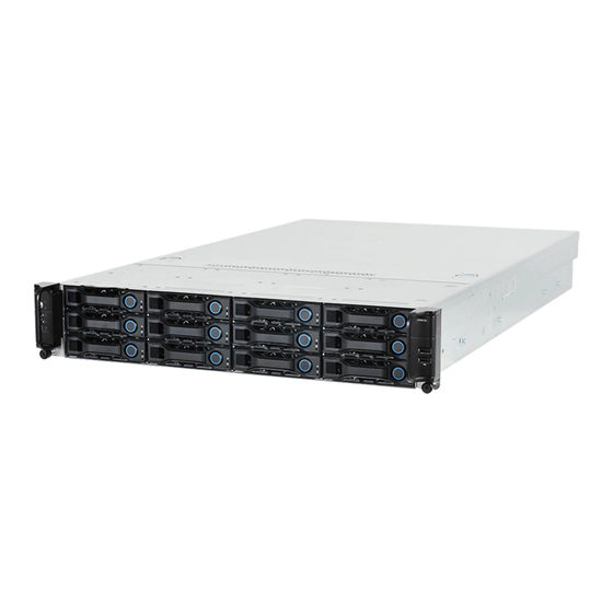
QuantaGrid Series
D51B-/D51BV-2U
Full-Featured Energy Efficient 2-Way Server
Energy Efficient 2-Socket GPU/ Xeon Phi™ Server
User's Guide
Version: 1.0
Table of
Contents
Previous
Page
Next
Page
1
2
3
4
5
Advertisement
Table of Contents
Need help?
Do you have a question about the D51BV-2U and is the answer not in the manual?
Ask a question
Questions and answers
Related Manuals for QUANTA D51BV-2U
Server QUANTA QuantaGrid Series User Manual
Versatile compact 2-socket server (138 pages)
Server QUANTA D51B-2U User Manual
Quantagrid series (65 pages)
Server QUANTA D51BP-1U User Manual
Quantagrid series energy efficient 2-socket server with extreme storage iop/s (34 pages)
Server QUANTA D51PC-1U User Manual
Versatile compact 2-socket server (138 pages)
Server quanta QSSC-S99K 2U User Manual
Multi-node system (177 pages)
Server Quanta S100-L11SL User Manual
Quanta 1u server user's guide (37 pages)
Server Quanta Stratos S810-X52L User Manual
Ultra dense high computing multi-node 2u server (42 pages)
Server QUANTA QSSC-980 User Manual
(138 pages)
Server QUANTA STRATOS S210 Series S210-X12RS Technical Manual
Ultra-socket high memory 1u rackmount server (272 pages)
Server QUANTA STRATOS S210 Series S210-X12MS Technical Manual
Two socket high performance & (223 pages)
Server QUANTA STRATOS S200 Series S200-X12TS Technical Manual
2-socket general purpose 1u server (245 pages)
Server QUANTA STRATOS S210 Series S210-X2A2J Technical Manual
Optimized 2-socket, 4-gpgpu 2u server (262 pages)
Server QUANTA S200-X12TS User Manual
S200 series 2-socket general purpose 1u server (53 pages)
Server Quanta QuantaGrid Q71L-4U User Manual
Powerful enterprise grade 4u 4-socket server with unprecedented ras and scalability (25 pages)
Server Quanta Rackgo X Series F03A Technical Manual
Superior serviceability 4 x compute node 2u server (162 pages)
Server QUANTA STRATOS S810 Series User Manual
Cluster-in-a-box server high density 2u shared storage (41 pages)
This manual is also suitable for:
D51b-2u
Quantagrid series
Table of Contents
Save PDF
Print
Rename the bookmark
Delete bookmark?
Delete from my manuals?
Login
Sign In
OR
Sign in with Facebook
Sign in with Google
Upload manual
Upload from disk
Upload from URL


Need help?
Do you have a question about the D51BV-2U and is the answer not in the manual?
Questions and answers