
Related Manuals for QUANTA QuantaGrid S31A-1U


Summary of Contents for QUANTA QuantaGrid S31A-1U
- Page 1 QuantaGrid Series S31A-1U Compact 1U Server with full feature User’s Guide Version: 1.0...
- Page 2 OPYRIGHT Copyright Copyright © 2015 Quanta Computer Inc. This publication, including all photographs, illus- trations and software, is protected under international copyright laws, with all rights reserved. Neither this guide, nor any of the material contained herein, may be reproduced without the express written consent of the manufacturer.
-
Page 3: Table Of Contents
ABLE OF ONTENT ABLE OF ONTENT About the System Introduction ............1-1 Package Contents . - Page 4 ABLE OF ONTENT Chipset Screen ........... 2-7 Server Management Screen.
- Page 5 ABLE OF ONTENT BMC Key Features and Functions........3-1 Power System .
- Page 6 ABLE OF ONTENT Server Information ..........3-16 FRU Information.
- Page 7 ABLE OF ONTENT BIOS Update ..........3-96 Log Out .
- Page 8 ONVENTIONS Conventions Several different typographic conventions are used throughout this manual. Refer to the following examples for common usage. Bold type face denotes menu items, buttons and application names. Italic type face denotes references to other sections, and the names of the folders, menus, programs, and files.
-
Page 9: Precautionary Measures
RECAUTIONARY EASURES Precautionary Measures Read all caution and safety statements in this document before performing any of the instructions. To reduce the risk of bodily injury, electrical shock, fire, and equipment dam- age, read and observe all warnings and precautions in this chapter before installing or maintaining your system. -
Page 10: Intended Application Uses
RECAUTIONARY EASURES Table 1: Warning and Cautions (Continued) The enclosure is designed to carry only the weight of the system sled. Do not use this equipment as a workspace. Do not place additional load onto any equipment in this system. Indicates two people are required to safely handle the system. -
Page 11: Equipment Handling Practices
RECAUTIONARY EASURES Equipment Handling Practices Reduce the risk of personal injury or equipment damage: Conform to local occupational health and safety requirements when moving and lifting equipment. Use mechanical assistance or other suitable assistance when moving and lifting equipment. -
Page 12: Rack Mount Warnings
RECAUTIONARY EASURES Rack Mount Warnings The following installation guidelines are required by UL for maintaining safety compliance when installing your system into a rack. The equipment rack must be anchored to an unmovable support to prevent it from tip- ping when your system or piece of equipment is extended from it. The equipment rack must be installed according to the rack manufacturer's instructions. -
Page 13: Cooling And Airflow
RECAUTIONARY EASURES Electrostatic Discharge (ESD) CAUTION! CAN DAMAGE DRIVES BOARDS AND OTHER PARTS E RECOMMEND THAT YOU PERFORM ALL PROCEDURES AT AN WORKSTATION F ONE IS NOT AVAILABLE PROVIDE SOME PROTECTION BY WEARING AN ANTI STATIC WRIST STRAP ATTACHED TO CHASSIS GROUND ANY UNPAINTED METAL SURFACE ON YOUR SERVER WHEN HANDLING PARTS... -
Page 14: General Information
RECAUTIONARY EASURES ified in this manual. Use of other products / components will void the UL listing and other regulatory approvals of the product and will most likely result in non-compliance with product regulations in the region(s) in which the product is sold. System power on/off: To remove power from system, you must remove the system from rack. - Page 15 RECAUTIONARY EASURES Assembly Safety Guidelines The power system in this product contains no user-serviceable parts. Refer servicing only to qualified personnel. The system is designed to operate in a typical office environment. Choose a site that is: Clean and free of airborne particles (other than normal room dust). ...
-
Page 16: Structure Of This Guide
RECAUTIONARY EASURES Structure of this guide Chapter 1: About the System “This section introduces the system, its different configuration(s) and the main features.” Chapter 2: BIOS “This section provides information regarding the BIOS architecture, BIOS update utility, server management, checkpoints, and error handling found in the sys- tem.”... -
Page 17: About The System
About the System Chapter 1 This section introduces the system, its different configuration(s) and the main features. -
Page 18: 1.1 Introduction
1.1 Introduction System Features The QuantaGrid S31A-1U with four 3.5” HDD is available in two models, a fixed PSU model and a redundant PSU model. The compact 1U server is built on the Intel® C236 chipset, featuring the Intel® Xeon® processor E3-1200 v5. - Page 19 BOUT THE YSTEM NTRODUCTION Table 1.1: System Specifications (Continued) PECIFICATIONS ESCRIPTION Onboard (Intel® C236): 2 mini-SAS HD connectors suppoting 8x SATA 6Gb/s ports Storage controller 2x M.2 connector supporting SATA or PCIe SSD Optional controller: Please refer to our Compatible Component List for more information LOM: ...
-
Page 20: 1.2 Package Contents
BOUT YOUR YSTEM ACKAGE ONTENTS 1.2 Package Contents (1) S31A-1U system (1) processor heat sink (1) power supply unit (1) power cord (optional) (1) utility CD (This Guide included) (1) rail kit Note: Note: For exact shipping contents, contact your sales representative. -
Page 21: 1.3 A Tour Of The System
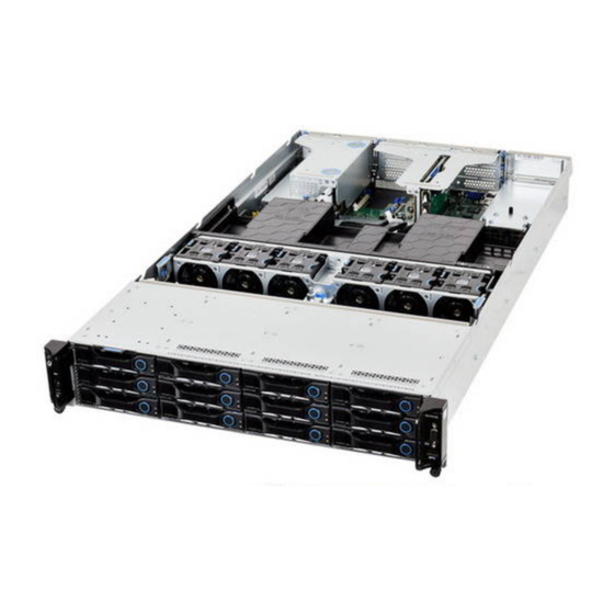
BOUT THE YSTEM OUR OF THE YSTEM 1.3 A Tour of the System System Overview The server is available as a redundant PSU (SKU1) and fixed PSU (SKU2) configuration. The redundant PSU SKU configuration system overview is displayed in the following image: Figure 1-1. - Page 22 BOUT THE YSTEM YSTEM VERVIEW The fixed PSU configuration system overview is displayed in the following image: Figure 1-2. Fixed PSU System (SKU2) Component Overview Table 2: Component Overview ESCRIPTION Fan module (3) System fan modules CPU socket LGA 1151 socket OCP mezz slot Support OCP mezzanine card, PCIe x8, Gen 3.0 ...
-
Page 23: System Front View
BOUT THE YSTEM YSTEM RONT System Front View Figure 1-3. System Front View Table 3: Front Panel View ESCRIPTION Front control panel See Front Control Panel LED on page 1-9 for further information. HDD bays 4 x 3.5” SAS/SATA HDD SSD tray 2 x SSD Front Control Panel (FCP) -
Page 24: System Rear View
BOUT THE YSTEM YSTEM Table 4: Front Control Panel Definition (Continued) ESCRIPTION Identification LED Activate ID LED to identify system ID button Toggles ID LED Power button Power on / off System Rear View Figure 1-5. System Rear View Table 5: System Rear View EATURE ESCRIPTION Upper: Redundant power supply unit. -
Page 25: System Rear I/O
BOUT THE YSTEM YSTEM System Rear I/O Figure 1-6. System Rear I/O Table 6: System Rear I/O Defintition ESCRIPTION ID button with LED Toggle the identification when pressing COM port DB9 port for debug or terminal concentrator Maximum display resolution: 1920x1200 32bpp@60Hz VGA connector (reduced blanking) USB ports... -
Page 26: Power Sub-System (Fixed Psu Sku)
LED S BOUT THE YSTEM TATUS EFINITIONS Table 7: Power Supply Units by Model AC I NPUT 2 x 400W high efficiency redundant PSU 100-240V AC 50/60Hz Power Sub-System (Fixed PSU SKU) Figure 1-8. Fixed PSU to Mainboard Module Description A fixed power supply unit is supplied in the system. -
Page 27: Lan Led
LED S BOUT THE YSTEM TATUS EFINITIONS Table 9: Front Control Panel LED Behavior (Continued) OLOR ONDITION ESCRIPTION Critical Failure: critical fan, voltage, temperature state. Blinking Non-Critical Failure: non-critical fan, voltage, temperature state, CPU thermal trip, DC off. Fault LED Amber SEL cleared Last pending warning or error has been de-asserted. -
Page 28: Bmc Management Port Led
LED S BOUT THE YSTEM TATUS EFINITIONS BMC Management Port LED The system mainboard includes GbE dedicated management port. The RJ45 connector has two built-in LEDs. See the following illustration and table for details. Activity Link PIN 1 Location Figure 1-11. RJ45 LAN Connector Table 11: RJ45 LED Description ONDITION CTIVITY... -
Page 29: Bios
BIOS Chapter 2 This section provides information regarding the BIOS architecture, BIOS update utility, server management, checkpoints, and error handling found in the system. -
Page 30: 2.1 Bios Setup Utility
The Keyboard Command Bar is located at the bottom right of the screen and con- mand Bar tinuously displays help for keyboard special keys and navigation keys. Entering BIOS Setup BIOS Setup is started by pressing <DEL> or <F2> during boot time when the OEM (Quanta) logo is displayed. -
Page 31: Keyboard Commands
BIOS EYBOARD OMMANDS When Quiet Boot is disabled, the message “press <DEL> or <F2> to enter setup” will be displayed on the diagnostics screen. Keyboard Commands The bottom right portion of the Setup screen provides a list of commands that are used to navigate through the Setup utility. - Page 32 BIOS EYBOARD OMMANDS Table 2: Keyboard Commands (Continued) PTION ESCRIPTION The minus key on the keypad is used to change the value of the cur- Change Value rent item to the previous value. This key scrolls through the values in the associated pick list without displaying the full list.
-
Page 33: Menu Selection Bar
BIOS ELECTION Menu Selection Bar The Menu Selection Bar is located at the top of the BIOS Setup Utility screen. It displays the major menu selections available to the user. By using the left and right arrow keys, the user can select the menus listed here. Server Platform Setup Utility Screens The sections below describe the screens available for the configuration of a server plat- form. -
Page 34: Main Screen
BIOS CREEN Main Screen Figure 2-1. Main Screen Table 3: Main Screen Description ETUP PTIONS OMMENTS Information only. Displays the BIOS Vendor BIOS Vendor. Information only. Displays the Core Version AMI BIOS Core version. Information only. Displays the Compliancy BIOS compliancy. Information only. -
Page 35: Advanced Screen
BIOS DVANCED CREEN Advanced Screen The Advanced screen provides an access point to configure several options. On this screen, the user selects the option that is to be configured. Configurations are performed on the selected screen, not directly on the Advanced screen. To access this screen from the Main screen, press the right arrow until the Advanced screen is chosen. -
Page 36: Chipset Screen
BIOS HIPSET CREEN Table 4: Advanced Screen Description (Continued) ETUP PTIONS OMMENTS Onboard Device Configuration Onboard Device Parameters iSCSI Configuration Configure the iSCSI Parameters Dynamic Chipset Screen The Chiptset screen provides an access point to configure several options. On this screen, the user selects the option that is to be configured. -
Page 37: Server Management Screen
BIOS ERVER ANAGEMENT CREEN Table 5: Chipset Screen Description (Continued) ETUP PTIONS OMMENTS System Agent (SA) Configuration System Agent (SA) Parameters PCH-IO Configuration PCH Parameters Server Management Screen The Server Management screen displays information of the BMC, and allows the user to configure desired settings. -
Page 38: Boot Options Screen
BIOS PTIONS CREEN Table 6: Server Management Screen Description (Continued) ETUP PTIONS OMMENTS [3 minutes] [4 minutes] FRB-2 Timer Enter value Between 3 to 6 min Not available if FRB2 Timer is dis- timeout for FRB-2 Timer Expiration value abled. [5 minutes] [6 minutes] Configure how the system... - Page 39 BIOS PTIONS CREEN If no boot devices are available – for example, both onboard LAN are disabled and no bootable device connected when Boot Mode is set to Legacy – the system will auto boot into BIOS setup menu. To access this screen from the Main screen, select Boot Options. Figure 2-5.
-
Page 40: Security Screen
BIOS ECURITY CREEN Table 7: Boot Options Screen Description (Continued) ETUP PTIONS OMMENTS [<Device String 1>] [<Device String 2>] Boot Option #1 Sets the system boot order … [Disabled] [<Device String 1>] [<Device String 2>] Boot Option #2 Sets the system boot order …... -
Page 41: Exit Screen
BIOS CREEN To access this screen from the Main screen, select the Security option. Figure 2-6. Security Screen Table 8: BIOS Screen Description ETUP PTIONS OMMENTS Administrator Password Set Administrator Password User Password Set User Password Secure Boot menu Customizable Secure Boot settings Exit Screen The Exit screen allows the user to choose to save or discard the configuration changes made on the other screens. - Page 42 BIOS CREEN Restore User Default Values is selected, the system is restored to the default values that the user saved earlier, instead of being restored to the factory defaults. Figure 2-7. Exit Screen Table 9: Exit Screen Description ETUP PTIONS OMMENTS Discard Changes Exit system setup without saving...
-
Page 43: Loading Bios Defaults
BIOS BIOS D OADING EFAULTS Table 9: Exit Screen Description (Continued) ETUP PTIONS OMMENTS [<Device String Boot with Device <Device String 6>] 6> Loading BIOS Defaults Different mechanisms exist for resetting the system configuration to the default values. When a request to reset the system configuration is detected, the BIOS loads the default system configuration values during the next POST. -
Page 44: 2.2 Bios Update Utility
BIOS BIOS U PDATE TILITY 2.2 BIOS Update Utility The flash ROM contains system initialization routines, the BIOS Setup Utility, and runtime support routines. The exact layout is subject to change, as determined by BIOS. The flash ROM also contains initialization code in compressed form for onboard peripherals, like SCSI, NIC and video controllers. -
Page 45: Bios Setting Utility
BIOS BIOS U PDATE TILITY Microcode updates. ME Firmware. BIOS Setting Utility Use AMISCE to import/export BIOS setting in Linux: 1. Export BIOS setting and generate script file: /o /s NVRAM.txt 2. Import BIOS setting with script file: /i /s NVRAM.txt BIOS Revision The BIOS revision is used to identify the BIOS image and BIOS phase. - Page 46 BIOS BIOS U PDATE TILITY Table 10: Terminology (Continued) Term Description Direct Memory Access. Direct Media Interface – connection from the processor to the PCH. DRAM Dynamic Random Access Memory, memory chips from which DIMMs are constructed. Driver Execution Environment. Component of Intel® Platform Innovation Framework for EFI architecture.
- Page 47 BIOS BIOS U PDATE TILITY Table 10: Terminology (Continued) Term Description Model Specific Register. Network Interface Card. Node Manager – now “Intel® Intelligent Power Node Manager”. Non-Maskable Interrupt. Original Equipment Manufacturer. Operating System. Platform Controller Hub. Peripheral Component Interconnect, or PCI Local Bus Standard – also called “Conven- tional PCI”.
-
Page 48: Clear Cmos
BIOS CMOS LEAR Table 10: Terminology (Continued) Term Description Stock Keeping Unit – indicates a specific marketing package, in this sense based around a server board configuration. SMBIOS System Management BIOS. System Management Interrupt. System Management Mode. Serial Over LAN. Serial Peripheral Interface, a serial data interface used for Flash memory. -
Page 49: 2.3 Server Management
BIOS ERVER ANAGEMENT 2.3 Server Management The BIOS supports many standard-based server management features and several propri- etary features. The Intelligent Platform Management Interface (IPMI) is an industry stan- dard and defines standardized, abstracted interfaces to platform management hardware. The BIOS implements many proprietary features that are allowed by the IPMI specification, but these features are outside the scope of the IPMI specification. -
Page 50: Reset
BIOS ONSOLE EDIRECTION Table 11: Keystroke Mappings (Continued) ANSI E SCAPE EQUENCE INDOWS LATFORM ESIGN <ESC>8 <ESC>9 <ESC>0 <ESC>! <ESC>@ Home <ESC>[<Shift>h <ESC>h <ESC>[<Shift>k <ESC>k <ESC>+ <ESC>- Page Up <ESC>? Page Down <ESC>/ Reset <ESC>R<ESC>r<ESC>R Standalone <Esc> Key for Headless Operation The Microsoft Headless Design Guidelines describes a specific implementation for the <Esc>... -
Page 51: Interface To Server Management (Optional)
BIOS BIOS S ETWORK UPPORT Interface to Server Management (Optional) If the BIOS determines that console redirection is enabled, it will read the current baud rate and pass this value to the appropriate management controller via the Intelligent Plat- form Management Bus (IPMB). Network BIOS Support PXE Boot The BIOS supports the EFI PXE implementation. - Page 52 BIOS HECKPOINTS Table 12: Checkpoint Range Description TATUS ESCRIPTION ANGE 0x01 – 0x0B SEC execution 0x0C – 0x0F SEC errors 0x10 – 0x2F PEI execution up to and including memory detection 0x30 – 0x4F PEI execution after memory detection 0x50 – 0x5F PEI errors 0x60 –...
- Page 53 BIOS HECKPOINTS PEI Phase Table 14: PEI Phase TATUS ESCRIPTION Progress Codes 0x10 PEI Core is started 0x11 Pre-memory CPU initialization is started 0x12 Pre-memory CPU initialization (CPU module specific) 0x13 Pre-memory CPU initialization (CPU module specific) 0x14 Pre-memory CPU initialization (CPU module specific) 0x15 Pre-memory North Bridge initialization is started 0x16...
-
Page 54: Dxe Phase
BIOS HECKPOINTS Table 14: PEI Phase (Continued) TATUS ESCRIPTION 0x3E Post-Memory South Bridge initialization (South Bridge module specific) 0x3F – 0x4E OEM post memory initialization codes 0x4F DXE IPL is started PEI Error Codes 0x50 Memory initialization error. Invalid memory type or incompatible memory speed 0x51 Memory initialization error. - Page 55 BIOS HECKPOINTS Table 15: DXE Phase (Continued) TATUS ESCRIPTION 0x62 Installation of the South Bridge Runtime Services 0x63 CPU DXE initialization is started 0x64 CPU DXE initialization (CPU module specific) 0x65 CPU DXE initialization (CPU module specific) 0x66 CPU DXE initialization (CPU module specific) 0x67 CPU DXE initialization (CPU module specific) 0x68...
- Page 56 BIOS HECKPOINTS Table 15: DXE Phase (Continued) TATUS ESCRIPTION 0x9A USB initialization is started 0x9B USB Reset 0x9C USB Detect 0x9D USB Enable 0x9E – 0x9F Reserved for future AMI codes 0xA0 IDE initialization is started 0xA1 IDE Reset 0xA2 IDE Detect 0xA3 IDE Enable...
-
Page 57: Acpi/Asl Checkpoints
BIOS HECKPOINTS Table 15: DXE Phase (Continued) TATUS ESCRIPTION 0xD4 PCI resource allocation error. Out of Resources 0xD5 No Space for Legacy Option ROM 0xD6 No Console Output Devices are found 0xD7 No Console Input Devices are found 0xD8 Invalid password 0xD9 Error loading Boot Option (LoadImage returned error) 0xDA... -
Page 58: Bmc
Chapter 3 This section provides information and key features of BMC (Baseboard Management Controller). -
Page 59: 3.1 Server Management Software
ERVER ANAGEMENT OFTWARE 3.1 Server Management Software Server System Overview In a server system, BMC is an independent system of the host server system. This indepen- dent system has its own processor and memory; the host system can be managed by the BMC system even if the host hardware or OS hangs or is unable to function. -
Page 60: Front Panel User Interface
RONT ANEL NTERFACE Front Panel User Interface The BMC provides control panel interface functionality including indicators (Fault/status and Identify LEDs) and buttons (Power/ID). Power Button The Power buttons allow to control the system status. ID Button The control panel Chassis Identify button toggles the state of the Chassis ID LED. If the ID LED is off, then a button press will turn the LED on (blinking). -
Page 61: Session And User
ERIAL Obtain System Event Log (SEL) entries Obtain Sensor Data Records (SDR) Set Platform Event Filtering (PEF) Set LAN configurations In addition, the BMC supports LAN alerting in the form of SNMP traps that conform to the IPMI Platform Event Trap (PET) format. -
Page 62: Bmc Firmware Update
BMC F IRMWARE PDATE All Platform Event Filter Table is default disabled. PEF Startup Delay and Last Processed Event tracking is not supported. PEF table lookup isn’t correlated to log SEL to SEL Repository. Serial Alerting is no support. ... -
Page 63: 3.2 Bmc Recovery
BMC R ECOVERY 3.2 BMC Recovery This section provides guidelines on BMC recovery process in DOS and Linux systems. Recovery Process in DOS System To recover BMC on a DOS system, do as follows: 1. Copy BMC firmware package to your USB key. 2. -
Page 64: 3.3 Smash
SMASH 3.3 SMASH Quanta SMASH is a tool that allows you to use Secure Shell (SSH) to login in the embedded Linux of BMC from remote terminal and gather information as well as give you control over things like power resets, power off. The basic structure is shown as below: Figure 3-1. -
Page 65: System Level Commands
SMASH Input command in Linux: ssh sysadmin@<Server IP> Figure 3-2. SMASH Activity Diagram Here provides you the commands about system level and BMC level. System Level Commands The system level commands provide you the information and power state control. Table 3.2: Targets and Verbs UPPORTED ERBS ELATED... - Page 66 SMASH Power-off system stop /SYS Power-reset system reset /SYS Display all system voltage show /SYS/voltage Display all system fan show /SYS/fan Display all system temperature show /SYS/temperature Display all system power supply show /SYS/powerSupply /SYS This command provides you the high-level status of the system chassis and main power subsystem.
- Page 67 SMASH /SYS/voltage This command returns a high level version of the system voltages health status. Table 3.4: /SYS/voltage ROPERTY ALID ALUE CCESS ESCRIPTION indicates the status not available /unknown (typically because system power is off) Sensor name list indicates the monitored parameters within normal operating ranges of voltage nonCritical nonCritical...
-
Page 68: Bmc Information
SMASH /SYS/powerSupply This command provides the specification of the Sensor Type sensor-specific event. Table 3.7: /SYS/powerSupply ROPERTY ALID ALUE CCESS ESCRIPTION Presence Detected Presence* indicates the Power Supply Presence detected Power Supply Fail- Power Supply Failure Detected ure Detected* Predictive Fail* indicates the Power Supply Failure detected Predictive Fail Sensor name list... - Page 69 SMASH show /SP Reset BMC reset /SP Set server identify LED to be off set /SP ServerIdentify=off Set server identify LED to be on set /SP ServerIdentify=on Set server identify LED to be blinking set /SP ServerIdentify=blinking Table 3.9: /SYS/fan ROPERTY ALID...
-
Page 70: Web Graphical User Interface (Gui) For Esms
(GUI) ESMS RAPHICAL NTERFACE 3.4 Web Graphical User Interface (GUI) for ESMS Using the Web GUI The BMC firmware features an embedded web server enabling users to connect to the BMC using a Web browser (e.g. Microsoft Internet Explorer). The Web GUI shows system information, system events, system status of managed servers, and other system-related information. -
Page 71: Dashboard
ASHBOARD Table 4: Default Username and Password IELD EFAULT Username qct.admin Password qct.admin After passing authentication, the following web page appears. Note: The default username and password are in lowercase characters. It is advised to change the admin password once you have logged in. Click the Help button on the right corner of the page for assistance, the Refresh button to refresh the page, or the Logout button to exit. -
Page 72: Device Information
Display current backplane firmware version. BMC NIC Display current used NIC. The maximum MAC address of system LAN port is 8. From Grantley plat- System MAC form, BMC supports to show LAN Card Type (LOM/OCP Mezzanine/ Quanta Mezzanine) for System MAC. 3-14... -
Page 73: Network Information
ASHBOARD Table 6: Device Information Page (Continued) ESCRIPTION BMC Date & Time The current time of BMC system. BMC Chipset This field shows BMC chipset type. Note: BMC Chipset type support list: (1) AST2300/AST2400: support virtual KVM function and related setting item. ... -
Page 74: Event Logs
ERVER NFORMATION Table 3-1: TATUS ICON ESCRIPTION Warning state Critical state If you click on , the sensor page for that particular sensor will be displayed. Event Logs A graphical representation of all events incurred by various sensors as well as occupied/ available space in logs. -
Page 75: Basic Information
FRU I NFORMATION To open the FRU Information Page, click on FRU Information on top menu. Select a FRU Device ID from the Basic Information section to view the details of the selected device. A screenshot of FRU Information page is shown as follows: Figure 3-7. -
Page 76: Product Information
FRU I NFORMATION Manufacture Date Time Board Manufacturer Board Product Name Board Serial Number Board Part Number FRU File ID Board Extra Product Information Product Information Area Format Version Language Manufacturer Name ... -
Page 77: Server Identify
FRU I NFORMATION Table 5: Component Information Page ESCRIPTION Displays the following information: CPU ID, Status, CPU Information Socket, Manufacturer, Model, Frequency Displays the following information: Memory ID, Status, Memory Information Socket, ... -
Page 78: Bios Post Code
FRU I NFORMATION Table 6: Server Identify Page (Continued) ESCRIPTION Perform Action Executes the selected Server Identify Operation. BIOS POST Code The page displays recent BIOS Port 80h POST code. Figure 3-10. BIOS POST Code Table 7: BIOS POST Code Page ESCRIPTION Current Codes Current BIOS Port 80h POST code... -
Page 79: Sensor Readings
FRU I NFORMATION The Server Health screenshot allows to select Sensor Readings or Event Log as shown in the following image: Figure 3-11. Server Health – Menu Sensor Readings In MegaRAC GUI, the Sensor Readings page displays all the sensor related information. To open the Sensor readings page, click Server Health >... - Page 80 FRU I NFORMATION you want to display in the list. Some examples of other sensors include Temperature Sen- sors, Fan Sensors, and Voltage Sensors etc. Select a particular sensor from the list. You can view the Thresholds for this sensor on the right hand side of the screen.
-
Page 81: Event Log
FRU I NFORMATION Live Widget The widget window can be turned On and Off for a selected sensor. Widget provides a dynamic representation of the readings for the sensor. The following image shows an example widget: Figure 3-13. Widget Window Note: Widgets are little gadgets, which provide real time information about a particular sensor. - Page 82 FRU I NFORMATION sensor type or sensor name filter options to view those specific events or you can also sort the list of entries by clicking on any of the column headers. To open the Event Log page, click Server Health > Event Log from the top menu. A sam- ple screenshot of the Event Log page is shown as follows.
- Page 83 FRU I NFORMATION Table 9: Event Log Page ESCRIPTION The category options: All Events, System Event Records, BIOS Generated Events, Event Log Category SMI Handler Events, System Management Software Events, System Software - OEM Events, ...
-
Page 84: Configuration Group
ONFIGURATION ROUP : Severity Unspecified Configuration Group Configuration Group page allows to access various configuration settings. A screenshot of the Configuration Group menu is shown in the following figure: Figure 3-15. Configuration Group Menu A detailed description of the Configuration menu is given in the following sections. Active Directory An active directory is a directory structure used on Microsoft Windows-based computers and servers to store information and data about networks and domains. - Page 85 ONFIGURATION ROUP To open Active Directory Settings page, click on Configuration > Active Directory from the main menu. A sample screenshot of Active Directory Settings Page is shown in the screenshot below. Figure 3-16. Active Directory Settings Page Table 10: Active Directory Settings Page ESCRIPTION This option is used to configure Active Directory Advanced Settings.
- Page 86 ONFIGURATION ROUP Procedure: Entering the details in Advanced Active Directory Settings Page 1. Click on Advanced Settings to open the Advanced Active Directory Settings Page. Figure 3-17. Advanced Active Directory Settings Page 2. In the Active Directory Settings page, select or unselect the Enable check box to enable or disable Active Directory Authentication respectively..
- Page 87 ONFIGURATION ROUP Note: Default Time out value: 120 seconds. Range from 15 to 300 allowed. 6. Configure IP addresses in Domain Controller Server Address1, Domain Control- ler Server Address2 & Domain Controller Server Address3. Note: IP address of Active Directory server: At least one Domain Controller Server Address must be configured.
-
Page 88: Dns
ONFIGURATION ROUP 5. Select the required options (KVM or VMedia) in the Extended Privilege. 6. Click Add to save the new role group and return to the Role Group List. 7. Click Cancel to cancel the settings and return to the Role Group List. To modify a Role Group 1. - Page 89 ONFIGURATION ROUP In DNS Server Settings page, you can click Configuration > DNS from the main menu. A DNS Server Settings Page is shown in the screenshot below. Figure 3-19. DNS Server Settings Page The fields of DNS Server Settings page are explained below. Table 11: DNS Server Settings Page ESCRIPTION OMAIN...
- Page 90 ONFIGURATION ROUP Table 11: DNS Server Settings Page (Continued) ESCRIPTION To enable/disable Register BMC. EGISTER TSIG Authentica- To enable/disable TSIG authentication while registering in DNS via tion Direct Dynamic DNS. Current TSIG Pri- The information of Current TSIG private file along with its up¬loaded TSIG vate File date/time will be displayed (read only).
- Page 91 ONFIGURATION ROUP 1. In Domain Name Service Configuration, Enable DNS Service. Check the option Enable to enable all the DNS Service Configurations. 2. Choose the Host Configuration either Automatic or Manual. Note: If you choose Automatic, you need not enter the Host Name and if you choose Manual, you need to enter the Host Name.
-
Page 92: Ldap/E-Directory
ONFIGURATION ROUP LDAP/E-Directory The Lightweight Directory Access Protocol (LDAP) is an application protocol for query- ing and modifying data of directory services implemented in Internet Protocol (IP) net- works. In MegaRAC GUI, LDAP is an Internet protocol that MegaRAC® card can use to authenticate users. - Page 93 ONFIGURATION ROUP Entering the details in Advanced LDAP/E-Directory Settings Page 1. In the LDAP Settings Page, click Advanced Settings. A sample screenshot of LDAP/E- Directory Settings page is given below. Figure 3-21. Advanced LDAP/E-Directory Settings 2. To enable/disable LDAP/E-Directory Authentication, check or uncheck the Enable checkbox respectively.
- Page 94 ONFIGURATION ROUP Note: Bind DN is a string of 4 to 64 alpha-numeric characters. It must start with an alphabetical character. Special Symbols like dot(.), comma(,), hyphen(-), underscore(_), equal-to(=) are allowed. Example: cn=manager, ou=login, dc=domain, dc=com . 8.
-
Page 95: Mouse Mode
ONFIGURATION ROUP 1. Select a blank row and click Add Role Group to open the Add Role Group Page as shown in the screenshot below from the LDAP/E-Directory Settings Page. Figure 3-22. Add Role Group Page 2. Enter the name that identifies the role group in the Role Group Name field. Note: ... - Page 96 ONFIGURATION ROUP menu. A sample screenshot of Mouse Mode Settings Page is shown in the screenshot below. Figure 3-23. Mouse Mode Settings Page The fields of Mouse Mode Settings page are explained below. Table 13: Mouse Mode Settings Page ESCRIPTION Absolute Mode The absolute position of the local mouse is sent to the server.
-
Page 97: Network
ONFIGURATION ROUP Note: Applicable for SLES Linux version SLES11. 2. Click Save button to save the changes made. 3. Click Reset to reset the modified changes. Network In MegaRAC GUI, the Network Settings Page is used to configure the network settings for the available LAN channels. - Page 98 ONFIGURATION ROUP Table 14: Network Settings Page ESCRIPTION LAN Interface Lists the LAN interfaces. LAN Settings To enable or disable the LAN Settings. This field displays the MAC Address of the device. This is a read only MAC Address field. This option lists the IPv4 configuration settings.
- Page 99 ONFIGURATION ROUP Table 15: Reserved IPv6 Address REFIX LLOCATION EFERENCE 0000::/8 Reserved by IETF [RFC4291] 0100::/8 Reserved by IETF [RFC4291] 0200::/7 Reserved by IETF [RFC4048] 0400::/6 Reserved by IETF [RFC4291] 0800::/5 Reserved by IETF [RFC4291] 1000::/4 Reserved by IETF [RFC4291] 4000::/3 Reserved by IETF [RFC4291]...
-
Page 100: Pef
ONFIGURATION ROUP 12. Click Reset if you want to reset the modified changes. Platform Event Filtering (PEF) provides a mechanism for configuring the BMC to take selected actions on event messages that it receives or has internally generated. These actions include operations such as system power-off, system reset, as well as triggering the generation of an alert. - Page 101 ONFIGURATION ROUP The fields of PEF Management – Event Filter Tab are explained below. This page contains the list of configured PEF’s. Table 16: PET Management - Event Filter ESCRIPTION PEF ID This field displays the ID for the newly configured PEF entry (read-only). Filter configuration Check box to enable the PEF settings.
- Page 102 ONFIGURATION ROUP Select any one of the Power action either Power down, Power reset or Power cycle from the drop down list Choose any one of the configured alert policy number from the drop down list. Note: Alert Policy has to be configured - under Configuration -> PEF -> Alert Policy. 5.
- Page 103 ONFIGURATION ROUP Note: Value ranges from 0 to 255. 8. In the Event Data 2 Configuration section, Event Data 2 AND Mask field is similar to Event Data 1 AND Mask. Event Data 2 Compare 1 & Event Data 2 Compare 2 fields are similar to Event Data ...
- Page 104 ONFIGURATION ROUP Table 17: PEF Management - Alert Policy ESCRIPTION Displays Policy entry number for the newly configured entry (read- Policy Entry # only). Policy Number Displays the Policy number of the configuration. Policy Configuration To enable or disable the policy settings. To choose any one of the Policy set values from the list.
- Page 105 ONFIGURATION ROUP 3. Policy Entry # is a read-only field. 4. Select the Policy Number from the list. 5. In the Policy Configuration field, check Enable if you wish to enable the policy set- tings. 6. In the Policy Set field, choose any of the Policy set from the list. 7.
- Page 106 ONFIGURATION ROUP PEF Management LAN Destination Page This page is used to configure the Event filter, Alert Policy and LAN destination. A sample screenshot of PEF Management LAN Destination Page is given below. Figure 3-29. PEF Management - LAN Destination The fields of PEF Management –...
- Page 107 ONFIGURATION ROUP Table 18: PEF Management - LAN Destination (Continued) ESCRIPTION These fields must be configured if e-mail alert is chosen as destination type with the user configured in FixedSubject-Format. If the selected user for mail alert is configured with AMI-Format then the Subject and message fields will be greyed out.
-
Page 108: Radius
ONFIGURATION ROUP 4. In the LAN Destination field, the destination for the newly configured entry is dis- played and this is a read-only field. 5. In the Destination Type field, select the one of the types. 6. In the Destination Address field, enter the destination address. Note: If Destination type is Email Alert, then give the email address that will receive the email. - Page 109 ONFIGURATION ROUP The fields of RADIUS Settings Page are explained below. Table 19: RADIUS Settings Page ESCRIPTION RADIUS Authentication Option to enable RADIUS authentication. The RADIUS Port number. Note: Port Default Port is 1812. Port value ranges from 1 to 65535. The IP address of RADIUS server.
-
Page 110: Remote Session
ONFIGURATION ROUP Remote Session In MegaRAC SP, use this page to configure virtual media configuration settings for the next redirection session. Encryption is disabled by default. To open Remote Session page, click Configuration > Remote Session from the main menu. A sample screenshot of Remote Session Page is shown in the screenshot below. Figure 3-32. -
Page 111: Smtp
ONFIGURATION ROUP Table 20: Remote Session Settings Page (Continued) ESCRIPTION Automatically OFF Local Monitor, When JViewer Enable/disable Automatically OFF Local Monitor, When JViewer Launches. Launches To save the current changes. Note: Save It will automatically close the existing remote redirection either KVM or Vir- tual media sessions, if any. - Page 112 ONFIGURATION ROUP To open SMTP Settings page, click Configuration > SMTP from the main menu. A sample screenshot of SMTP Settings Page is shown in the screenshot below. Figure 3-33. SMTP Settings Page The fields of SMTP Settings Page are explained below. Table 21: SMTP Settings Page ESCRIPTION LAN Channel Number...
- Page 113 ONFIGURATION ROUP Table 21: SMTP Settings Page (Continued) ESCRIPTION Enable/disable SMTP Authentication. Note: SMTP Server Authentication Types supported are: CRAM-MD5 SMTP Server requires Authentication LOGIN PLAIN If the SMTP server does not support any one of the above authentication types, the user will get an error message stating, "Authentication type is not supported by SMTP Server"...
-
Page 114: Sol
ONFIGURATION ROUP Note: The Server Address can be edited only when the SMTP Support option is enabled. 5. Enter the Port value in the specified field. 6. Enter the Server Address in the specified field. 7. Enable the check box SMTP Server requires Authentication if you want to authen- ticate SMTP Server. -
Page 115: Ssl
ONFIGURATION ROUP Table 22: SOL Settings Page ESCRIPTION Enable Serial over LAN Checked=Enabled; Unchecked=Disabled. Select the IPMI Serial over LAN minimum user privilege: Administrator Channel Privilege Level Limit Operator User Save Use this button to save your settings. Advanced SOL Settings Use this button to go to advanced SOL page. - Page 116 ONFIGURATION ROUP To open SSL Certificate Configuration page, click Configuration > SSL from the main menu. There are three tabs on this page. Upload SSL option is used to upload the certificate and private key file into the BMC. Generate SSL option is used to generate the SSL certificate based on configuration ...
- Page 117 ONFIGURATION ROUP Note: Upon successful upload, HTTPs service will get restarted to use the newly uploaded SSL certif- icate. Figure 3-37. SSL Certificate Configuration – Generate SSL The fields of SSL Certificate Configuration – Generate SSL tab are explained below. Table 25: SSL Certificate Configuration - Generate SSL ESCRIPTION Common name for which certificate is to be generated.
- Page 118 ONFIGURATION ROUP Table 25: SSL Certificate Configuration - Generate SSL (Continued) ESCRIPTION Validity of the certificate. Vaild for Value ranges from 1 to 3650 days. Key Length The key length bit value of the certificate. Generate To generate the new SSL certificate. Note: HTTPs service will get restarted, to use the newly generated SSL certificate.
- Page 119 ONFIGURATION ROUP Table 26: SSL Certificate Configuration – View SSL (Continued) ESCRIPTION This section describes the following Certificate Issuer information. Common Name (CN) Organization (O) Organization Unit (OU) Issued From City or Locality (L) State or Province (ST) ...
-
Page 120: User Management
ONFIGURATION ROUP Note: Once you Upload/Generate the certificates, only HTTPs service will get restarted. ® You can now access your Generic MegaRAC SP securely using the following format in ® your IP Address field from your Internet browser: https://<your MegaRAC SP’s IP address here>... - Page 121 ONFIGURATION ROUP Table 27: User Management Page (Continued) ESCRIPTION User Access To enable or disable the access privilege of the user. Network Privilege Displays the network access privilege of the user. SNMP Status Displays if the SNMP status for the user is Enabled or Disabled. E-mail ID Displays e-mail address of the user.
- Page 122 ONFIGURATION ROUP 3. In the Password and Confirm Password fields, enter and confirm your new pass- word. Note: Password must be at least 4 characters long. White space is not allowed. This field will not allow more than 20 characters if “20 Bytes” option is chosen. 4.
- Page 123 ONFIGURATION ROUP Fixed-Subject Format: This format displays the message according to user's setting. You must set the subject and message for email alert. 12. In the New SSK Key field, click Browse and select the SSH key file. Note: SSH key file should be of pub type.
-
Page 124: Virtual Media
ONFIGURATION ROUP Virtual Media In MegaRAC GUI, this page is to configure Virtual Media device settings. If you change the configuration of the virtual media in this page, it shows the appropriate device in the JViewer Vmedia dialog. For example, if you select two floppy devices in Configure Virtual Media page, then in JViewer >... -
Page 125: Services
ONFIGURATION ROUP Procedure: 1. Select the number of Floppy devices, CD/DVD devices and Hard disk devices from the dropdown list. Note: Maximum of two devices can be added in Floppy, CD/DVD and Hard disk drives. 2. Enable the Local Media Support if needed. 3. - Page 126 ONFIGURATION ROUP Table 29: Services (Continued) ESCRIPTION Interfaces It shows the interface in which service is running. This port is used to configure non secure port number for the service. - Web default port is 80 - KVM default port is 7578 - CD Media default port is 5120 - FD Media default port is 5122 - HD Media default port is 5123...
- Page 127 ONFIGURATION ROUP 2. This opens the Active Session screen (for example - Web Service screen) as shown in the screenshot below. Session ID: Displays the ID number of the active sessions. Session Type: Displays the type of the active sessions. IP Address: Displays the IP addresses that are already configured for the active sessions.
-
Page 128: Lan Port Settings
EMOTE ONTROL Note: Interfaces, Nonsecure port, Secure port, Time out and Maximum Sessions will not be active unless the current state is active. 5. Choose any one of the available interfaces from the Interface drop-down list. 6. Enter the Nonsecure port number in the Nonsecure Port field. 7. -
Page 129: Console Redirection
EMOTE ONTROL A sample screenshot of the Remote Control menu is given below. Figure 3-46. Remote Control Menu A detailed description of the menu items are given ahead Console Redirection The remote console application, which is started using the WebGUI, allows you to control your server's operating system remotely, using the screen, mouse, and keyboard, and to redirect local CD/DVD, Floppy diskette and Hard disk/USB thumb drives as if they were connected directly to the server. - Page 130 EMOTE ONTROL FC 9 - 32 bit FC 9 - 64 bit FC 10 - 32 bit FC 10 - 64 bit FC 12 - 32 bit FC 12 - 64 bit FC 13 - 32 bit ...
-
Page 131: Browser Settings
EMOTE ONTROL Browser Settings For Launching the KVM, pop-up block should be disabled. For Internet explorer, enable the download file options from the settings. Java Console This is an OS independent plug-in which can be used in Windows as well as Linux with the help of JRE. - Page 132 EMOTE ONTROL Video This menu contains the following sub menu items. Table 30: Video ESCRIPTION Pause redirection This option is used for pausing Console Redirection. This option is used to resume the Console Redirection when the session Resume Redirection is paused. This option can be used to update the display shown in the Console Refresh Video Redirection window.
- Page 133 Table 31: Keyboard (Continued) ESCRIPTION This menu item can be used to act as the right-side <WIN> key when in Right Windows Key Console Redirection. You can also decide how the key should be pressed: Hold Down or Press and Release. This menu item can be used to act as if you depressed the <CTRL>, Alt+Ctrl+Del <ALT>...
- Page 134 EMOTE ONTROL Table 31: Keyboard (Continued) ESCRIPTION Procedure: 1. Click Keyboard > Hot Keys > Add Hot Keys to show below snap- shot Add: used to add User Defined Macros Delete: used to delete User Defined Macros Close: used to close User Defined Macros window 2.
- Page 135 EMOTE ONTROL Mouse This menu contains the following sub menu items. Table 32: Mouse ESCRIPTION This option is used to display or hide the client mouse cursor in Java Show cursor Console. Mouse Calibration It is used to adjust the mouse calibration. ...
- Page 136 EMOTE ONTROL Media Figure 3-47. Virtual Media Table 34: Virtual Media ESCRIPTION This menu item can be used to start or stop the redirection of a physical floppy drive and floppy image types such as *.img. Floppy Key Media Note: Floppy Redirection is not an available feature on all versions of the Meg- aRAC®...
-
Page 137: Keyboard Layout
EMOTE ONTROL Keyboard Layout Table 35: Keyboard Layout ESCRIPTION This option is used to detect keyboard layout automatically. The lan- guages supported automatically are English – US, French – France, Auto Detect Spanish – Spain, German- Germany, Japanese- Japan. If the client and host languages are the same, then for all the languages other than Eng- lish mentioned above, you must select this option to avoid typo errors. - Page 138 EMOTE ONTROL 1. Click Video Record > Settings to open the settings page as shown in the screen- shot below. Figure 3-48. Video Record Settings Page 2. Enter the Video Length in seconds. 3. Browse and enter the location where you want the video to be saved. 4.
- Page 139 EMOTE ONTROL The Remote KVM console is only able to allow two users to login simultaneously. Regard- ing to KVM privilege, the first user has the greatest power to decide the second user access right. The second user wants to launch remote KVM if first user already login remote KVM, and second user needs to wait for first user permit in 30 seconds, then second user will get the waiting information as shown below.
-
Page 140: Server Power Control
EMOTE ONTROL Deny Access: Second user can not have any access right to access Keyboard, mouse, and Video function. Server Power Control This page allows you to view and control the power of your server. In Power Control and Status page, you can click Remote Control > Server Power Control from the main menu, and then there are more options to control server system. -
Page 141: Java Sol
EMOTE ONTROL Table 37: Server Power Control ESCRIPTION Reset Server This option will reboot the system without powering off (warm boot). Power off Server – Immediate This option will immediately power off the server. Power off Server – Orderly Shut- This option will initiate operating system shutdown prior to the shut- down down. - Page 142 EMOTE ONTROL Table 38: Server Power Control (Continued) ESCRIPTION Power off Server – Orderly Shut- This option will initiate operating system shutdown prior to the shut- down down. Power On Server This option will power on the server. Power Cycle Server This option will first power off, and then reboot the system (cold boot).
-
Page 143: Maintenance Group
AINTENANCE ROUP 4. Click Connect to open the SOL redirection window as shown in the screenshot below. Maintenance Group This group of pages allows you to do maintenance tasks on the device. The menu contains the following items: Preserve Configuration ... -
Page 144: Preserve Configuration
AINTENANCE ROUP Preserve Configuration This page allows the user to configure the preserve configuration items, which will be used by the Restore factory defaults to preserve the existing configuration without over- writing with default configuration. Figure 3-52. Preserve Configuration Page Item Verification Procedure 1. - Page 145 AINTENANCE ROUP Step 4: upgrade firmware Step 5: after Step 4, go to Step 2 and check if the event is still preserved (if preserved then PASS, else FAIL) 3. IPMI Step 1: Please add a new user by Web. Step 2: check if the user added Step 3: go to Web-UI to check “IPMI”...
-
Page 146: Restore Factory Defaults
AINTENANCE ROUP Step 3: go to Web-UI to check "KVM" to be preserved Step 4: upgrade firmware Step 5: after Step 4, go to Step 2 and check if the setting is still preserved (if preserved then PASS, else FAIL) 8. -
Page 147: Firmware Update
IRMWARE PDATE To open Restore Factory Defaults page, click Maintenance > Restore Factory Defaults from the main menu. A sample screenshot of Restore Factory Defaults Page is shown in the screenshot below. Figure 3-53. Restore Factory Defaults Page Procedure: Click Restore Factory to restore the factory defaults of the device firmware. Firmware Update This group of pages allows you to do Firmware Update on the device. - Page 148 IRMWARE PDATE option to preserve configuration will be presented. Enable it, if you wish to preserve con- figured settings through the upgrade. WARNING! Please note that after entering update mode widgets, other web pages and services will not work. All open widgets will be closed automatically. If upgrade process is cancelled in the mid- dle of the wizard, the device will be reset.
- Page 149 IRMWARE PDATE To process HPM Firmware Upgradation, select HPM option and click Continue to upgrade the current device firmware. The screenshot of HPM Firmware Update is as shown below. Note: All configuration items below will be preserved as default during the restore configuration operation.
- Page 150 IRMWARE PDATE Preserve Status: The status of the Preserve Configuration items. Procedure 1. To proceed HPM Firmware Update, click Continue. The Firmware update undergoes the following steps: a. Click Choose File to browse and select the Firmware image to flash and click Ok. Note: While creating HPM image with multiple components, Boot and App compo- nents should be placed at the end of the conf file.
- Page 151 IRMWARE PDATE This wizard takes you through the process of AMI based firmware upgrade. To process AMI Firmware Upgrade, select AMI option and click Continue to upgrade the current device firmware. The screenshot of AMI Firware Update is as shown below. Note: All configuration items below will be preserved as default during the restore configuration operation.
- Page 152 IRMWARE PDATE Procedure Note: To configure Protocol information, choose Protocol Configuration under Firmware Update menu. To configure Image to be booted from upon Reset, choose Dual Image Configuration under Firmware Update menu. 1. Check the option Preserve All Configuration to preserve all the listed configura- tions.
- Page 153 IRMWARE PDATE d. Browse and select the Firmware image to flash and click Upload. e. Verifying Firmware Image In Section Based Firmware Update, you can configure the firmware image for section based flashing. Check the required sections and click Proceed to update the firmware. If flashing is required for all images, select the option Full Flash .
-
Page 154: Bios Update
The device will reset if update is canceled. The device will also reset upon successful completion of firmware update. BIOS Update This page allow user to update BIOS image, but only works when DC is off. Please note the filename extension of BIOS image shall be *.bin. For example: BIOS3A22.bin. After BIOS update complete, system must perform AC cycle to take effect. - Page 155 RIVILEGE change BMC configuration, just to trigger Identify LED used to display where Server is. So it is expected behavior. After checked other Operator privilege command by IPMI 2.0 Specification, Chassis Control command (Power On/ Off) is also allowed. But in our code base, we raise Chassis Control com- mand to be Administrator to protect system.
-
Page 156: Regulatory And Compliance Information
Regulatory and Compliance Information Chapter 4 This section provides regulatory and compliance information applicable to this system. -
Page 157: 4.1 Electromagnetic Compatibility Notices
EGULATORY AND OMPLIANCE NFORMATION LECTROMAGNETIC OMPATIBILITY OTICES 4.1 Electromagnetic Compatibility Notices FCC Verification Statement (USA) This device complies with Part 15 of the FCC Rules. Operation is subject to the following two conditions: (1) this device may not cause harmful interference, and (2) this device must accept any interference received, including interference that may cause undesired operation. -
Page 158: Regulated Specified Components
Restriction of Hazardous Substances (RoHS) Compliance Quanta Computer Inc. has a system in place to restrict the use of banned substances in accordance with the European Directive 2011/65/EU. Compliance is based on declaration that materials banned in the RoHS Directive are either (1) below all applicable threshold limits or (2) an approved / pending RoHS exemption applies. -
Page 159: Product Regulatory Compliance Markings
EGULATORY AND OMPLIANCE NFORMATION RODUCT EGULATORY OMPLIANCE ARKINGS 4.2 Product Regulatory Compliance Mark- ings This product is marked with the following product certification markings: Table 1: Product Regulatory Compliance Markings EGULATORY OMPLIANCE EGION ARKING cULus Listing Mark USA / Canada CE Mark Europe This device complies with Part 15 of the FCC Rules.
Need help?
Do you have a question about the QuantaGrid S31A-1U and is the answer not in the manual?
Questions and answers