
Related Manuals for QUANTA STRATOS S210 Series S210-X2A2J


Summary of Contents for QUANTA STRATOS S210 Series S210-X2A2J
- Page 1 STRATOS S210 Series S210-X2A2J Optimized 2-Socket, 4-GPGPU 2U Server Technical Guide Document Version: 1.0.1...
-
Page 2: Table Of Contents
ABLE OF ONTENTS ABLE OF ONTENTS About the Server Introduction System Features ..............1-1 Specifications . - Page 3 ABLE OF ONTENTS Installing Hardware Safety Measures Hard Disk Drive Removing a Swappable HDD Assembly ........... .2-2 Installing a Swappable HDD Assembly .
- Page 4 ABLE OF ONTENTS General-purpose Graphics Processing Units 2-10 GPGPU Location Overview .............2-10 Screw Tension Specification .
- Page 5 ABLE OF ONTENTS Installing a PDB Air Duct ............. . .2-54 Removing a GPGPU3 Air Duct .
- Page 6 ABLE OF ONTENTS Power Distribution Board 2-69 Removing a PDB ..............2-69 Installing a PDB .
- Page 7 ABLE OF ONTENTS Runtime Error Logging Screen............3-15 SATA Controller Screen .
- Page 8 ABLE OF ONTENTS BIOS Update Utility 3-48 BIOS Update Utility ..............3-48 Recovery Mode .
- Page 9 ABLE OF ONTENTS Server Management Software Introduction ................4-1 BMC Key Features and Functions .
- Page 10 ABLE OF ONTENTS BMC Recovery Recovery Process in DOS System ............4-6 Recovery Process in Linux System .
- Page 11 ABLE OF ONTENTS FRU Information..............4-12 Server Component .
- Page 12 ABLE OF ONTENTS Remote Control ..............4-51 Console Redirection .
- Page 13 ABLE OF ONTENTS Protected RTC Jumper (J6C3)............5-5 ME Disable Jumper (J6B6) .
- Page 14 ABLE OF ONTENTS Installation and Assembly Safety Instructions Installation Assembly Safety Instructions Guidelines ................8-1 Safety Information Server Safety Information Safety Warnings and Cautions .
- Page 15 ABLE OF ONTENTS Regulatory and Compliance Information Product Regulatory Compliance Markings 10-1 Electromagnetic Compatibility Notices 10-2 FCC Verification Statement (USA)............10-2 Europe (CE Declaration of Conformity) .
- Page 16 ONVENTIONS Conventions Several different typographic conventions are used throughout this technical guide. Refer to the following examples for com- mon usage. Bold type face denotes menu items, buttons and application names. Italic type face denotes references to other sections, and the names of the folders, menus, programs, and files.
- Page 17 CRONYMS Acronyms EFINITION EFINITION A signal is deasserted when in the inactive state. Analog to Digital Active-low signal names have “_L” appended to the ACPI Advanced Configuration and Power Interface end of the signal mnemonic. Active-high signal names Deasserted have no “_L” suffix. To reduce confusion when referring Alerting Standard Forum to active-high and active-low signals, the terms one/ Active-high (positive true) signals are asserted when in...
- Page 18 CRONYMS EFINITION EFINITION IPMI Intelligent Platform Management Interface Unit of electrical resistance In-Target Probe Power Distribution Board 1024 bytes. Platform Event Filtering Keyboard Controller Style Platform Event Paging Keyboard, Video, Mouse PERR Parity Error Local Area Network Power-On Hours Liquid Crystal Display POST Power-On Self Test Lower Critical Threshold...
- Page 19 CRONYMS EFINITION Server Management Mode Server Management Software SNMP Simple Network Management Protocol Serial Over LAN UART Universal Asynchronous Receiver/Transmitter Upper Critical Threshold User Datagram Protocol UNCT Upper Non-Critical Threshold UNRT Upper Non-Recoverable Threshold Watchdog Timer Word 16-bit quantity...
-
Page 20: Important Safety Instructions
AFETY NFORMATION Safety Information Important Safety Instructions modems attached to the server before opening it. Otherwise, personal injury or equipment damage can result. Read all caution and safety statements in this document before Electrostatic discharge (ESD) and ESD protection: ESD can performing any of the instructions. - Page 21 AFETY NFORMATION...
-
Page 22: Revision History
HAPTER PDATES Copyright Disclaimer Copyright © 2014 Quanta Computer Inc. This publication, The information in this document is subject to change without including all photographs, illustrations and software, is pro- notice. The manufacturer makes no representations or warran- tected under international copyright laws, with all rights ties with respect to the contents hereof and specifically dis- reserved. - Page 23 About the Server Chapter 1...
-
Page 24: Introduction
BOUT THE ERVER NTRODUCTION 1.1. Introduction System Features ® The S210-X2A2J is a 2U high system, based on Intel Romley-EP platform.The platform supports high performance 8-core processors Sandy Bridge and Patsburg PCH. The Sandy Specifications Bridge processor has an integrated DDR3 memory controller (iMC) with four memory channels that support up to 3 ECC registered DIMMs or unbuffered DIMMs (ECC or non-ECC) per memory Specification... - Page 25 BOUT THE ERVER YSTEM EATURES Specification (Continued) Specification (Continued) PECIFICATION ESCRIPTION PECIFICATION ESCRIPTION HDD Backplane 1 to 1 Operating temperature: 10°C to 35°C (50°F to 95°F) PCIe Expansion Slot (4) PCIe x16 slots Non-operating temperature: -40°C to 70°C (- ...
-
Page 26: Package Contents
BOUT THE ERVER ACKAGE ONTENTS 1.2. Package Contents The following list includes the package components: 1x 2U server chassis 2x Processor heat sink 16x Dummy DIMM 2x Power supply 1x Power cord (optional) 1x Utility CD (Technical Guide included) ... -
Page 27: A Tour Of The System
BOUT THE ERVER OUR OF THE YSTEM 1.3. A Tour of the System System Overview System Component Overview General-purpose graphics processing unit (GPGPU)4 GPGPU2 GPGPU3 GPGPU1 Mainboard Power distribution board (PDB) air duct Chassis Control panel Hot-swappable HDD (x4) Fan module (x4) GPGPU3 air duct Mainboard air duct System Component Overview... -
Page 28: System Front View
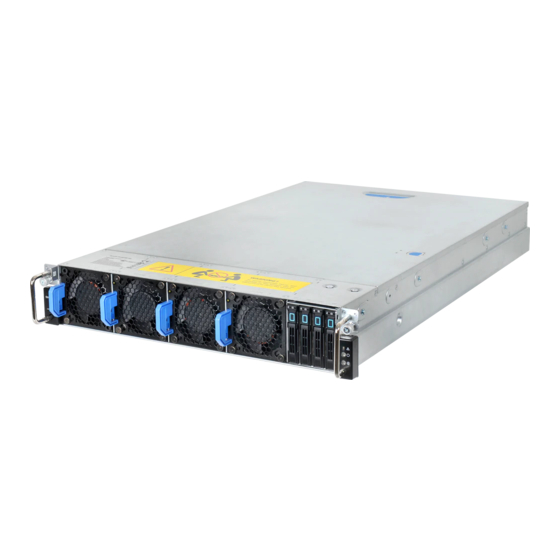
BOUT THE ERVER YSTEM RONT System Front View Control Panel System Front View Control Panel System Front View Control Panel Hot-swappable hard disk drives (x4) Front panel Fault/ status LED Fan module (x4) Power/ sleep button with LED ID button with LED... -
Page 29: System Rear View
BOUT THE ERVER YSTEM System Rear View I/O Ports on Rear Panel Mainboard I/O Ports System Rear View Mainboard I/O Ports System Rear View NIC1 LAN port The venting holes for GPU1 I/O ports NOTE: See I/O Ports on Rear Panel. NIC2 LAN port Power supply unit (x2) VGA port... -
Page 30: Led Status Definitions
LED S BOUT THE ERVER TATUS EFINITIONS LED Status Definitions Front Panel LED (Continued) OLOR ONDITION ESCRIPTION Front Control Panel System health error, reported by Amber Blink AC power off: system pow- ered off Fault/ Status AC power on: system pow- ... -
Page 31: Amber Blinking Identification
LED S BOUT THE ERVER TATUS EFINITIONS Amber Blinking Identification LAN LED The system mainboard has one I350 Ethernet controller and Amber Blinking Identification two 1GbE ports. Each RJ45 connector has two built-in LEDs. See the following illustration and table for details. ENSOR CTION Temperature sensor... -
Page 32: Hdd Led
LED S BOUT THE ERVER TATUS EFINITIONS HDD LED Activity LED Status/ fail LED Front HDD LED HDD LED TATUS HDD S TATE CTIVITY Slot empty Blinking when Drive online activity On 400 msec Blinking when Drive rebuilding activity Off 100 ... -
Page 33: Installing Hardware
Installing Hardware Chapter 2... -
Page 34: Safety Measures
NSTALLING ARDWARE AFETY EASURES 2.1. Safety Measures WARNING! WARNING! Wear a grounded wrist strap. If none are available, discharge Always ask for assistance to move or lift the system. any personal static electricity by touching the bare metal chassis of the server case, or the bare metal body of any other grounded device. -
Page 35: Hard Disk Drive
NSTALLING ARDWARE RIVE 2.2. Hard Disk Drive Removing a Swappable HDD 2. Pull the HDD tray handle open. Assembly WARNING! Do not operate the system without all hard drive trays inserted into the chassis. All hard drive bays must be occupied by either a hard drive or an empty hard drive tray. -
Page 36: Installing A Swappable Hdd Assembly
HDD A NSTALLING ARDWARE NSTALLING A WAPPABLE SSEMBLY Installing a Swappable HDD Removing an HDD Module Assembly Prerequisite: Remove the swappable HDD assembly. See 1. Inser the HDD assembly into the system. Make sure hard disk drive is fully inserted. 1. -
Page 37: Installing An Hdd Module
HDD M NSTALLING ARDWARE NSTALLING AN ODULE Installing an HDD Module 1. Align the screw holes on HDD module with the screw holes on the HDD tray, circuit board facing the HDD tray. 2. Install the HDD module into the HDD tray. 3. -
Page 38: Power Supply Unit
NSTALLING ARDWARE OWER UPPLY 2.3. Power Supply Unit Removing a PSU Note: Partial redundancy is supported on desigs with a throttling fea- ture to downgrade power consumption when a PSU is faulty or 1. Disconnect the power cord from the PSU. has been removed. -
Page 39: Installing A Psu
NSTALLING ARDWARE NSTALLING A Installing a PSU 1. Insert the PSU into the system until flush with the chassis. 2. Pull down the PSU handle. 3. Connect the power cord into the PSU. Installing PSU... -
Page 40: Fan
NSTALLING ARDWARE 2.4. Fan Removing a Swappable Fan Installing a Swappable Fan Assembly Assembly 1. Press the release latch. Prerequisite: Remove the top cover. See Opening the Top Cover . 2. Pull the fan assembly out of the system. CAUTION! N CASE OF A ROTOR OR FAN FAILURE REPLACE THE FAN MOD ... - Page 41 NSTALLING ARDWARE NSTALLING A WAPPABLE SSEMBLY Insert the fan assembly into the system until flush with the chas- sis. Installing Fan Assembly...
-
Page 42: Top Cover
NSTALLING ARDWARE OVER 2.5. Top Cover Removing a Top Cover Installing a Top Cover 1. Press the release button (A) and slide the top cover. 1. Place the top cover on the chassis. 2. Lift the top cover off the chassis. 2. -
Page 43: General-Purpose Graphics Processing Units
NSTALLING ARDWARE ENERAL PURPOSE RAPHICS ROCESSING NITS 2.6. General-purpose Graphics Processing Units GPGPU Location Overview Screw Tension Specification When securing the screws to the GPGPU module, make sure to follow the screw torque. See the information on illustrations next to a corresponding screw. GPGPU2 Removing a GPGPU1 Module GPGPU1... - Page 44 GPGPU1 M NSTALLING ARDWARE EMOVING A ODULE 2. Release the GPGPU1 assembly from the tabs and stand- M2075/M2090 SKU: off on the chassis. Standoff Removing GPGPU1 Assembly Removing Screws (M2075/M2090) 3. Remove the screw(s) securing the GPGPU1module to the assembly. 4.
- Page 45 GPGPU1 M NSTALLING ARDWARE EMOVING A ODULE K10/K20/K20X/K520 SKU: Xeon Phi™ SKU: Removing Screws (K10/K20/K20X/K520) Removing Screws (Xeon Phi™) 5. Place the GPGPU1 assembly on the surface, board side upwards. 6. Remove the screw(s) securing the GPGPU riser card to the assembly.
- Page 46 GPGPU1 M NSTALLING ARDWARE EMOVING A ODULE 7. Remove the GPGPU riser card. M2075/M2090 SKU: Removing GPGPU Riser Card Removing Screws (M2075/M2090) 8. Remove the screw(s) securing the GPGPU1 module to the assembly bracket(s). 9. Remove the bracket(s). 2-13...
- Page 47 GPGPU1 M NSTALLING ARDWARE EMOVING A ODULE K520/K10/K20/K20X SKU: Xeon Phi™ SKU: Removing Screws (K520/K10/K20/K20X SKU) Removing Screws (Xeon Phi™ SKU) If the GPGPU module is not intended to install, to complete the procedure, install a dummy bracket to the GPGPU bracket. See Installing a GPGPU Dummy Bracket .
-
Page 48: Installing A Gpgpu1 Module
GPGPU1 M NSTALLING ARDWARE NSTALLING A ODULE Installing a GPGPU1 Module 2. Secure the GPGPU riser card to the assembly with the screw(s). Prerequisite: Remove the top cover. See Opening the Top Cover . To install the GPGPU modue, make sure to remove the dummy bracket from the GPGPU bracket if present. - Page 49 GPGPU1 M NSTALLING ARDWARE NSTALLING A ODULE M2075/M2090 SKU: K520/K10/K20/K20X SKU: 5.0~5.5 kg/cm 5.0~5.5 kg/cm Installing Screws (K520/K10/K20/K20X) 6.6~7.2 kg/cm Installing Screws (M2075/M2090) 2-16...
- Page 50 GPGPU1 M NSTALLING ARDWARE NSTALLING A ODULE Xeon Phi™ SKU: M2075/M2090 SKU: 5.0~5.5 kg/cm 10~11 kg/cm 6.6~7.2 kg/cm 6.2~7.2 kg/cm 10~11 kg/cm Installing Screws (Xeon Phi™) Installing Screws (M2075/M2090) 5. Align the screw holes on GPGPU1 module with the scew holes on the assembly.
- Page 51 GPGPU1 M NSTALLING ARDWARE NSTALLING A ODULE K10/K20/K20X/K520 SKU: Xeon Phi™ SKU: 10~11 kg/cm 10~11 kg/cm 6.6~7.2 kg/cm Installing Screws (K10/K20/K20X/K520) 10~11 kg/cm Installing Screws (Xeon Phi™) 8. Flip the GPUGPU1 assembly 9. Align the screw and pin hole on the GPGPU1 assembly with the screw hole and pin on the chassis.
-
Page 52: Removing A Gpgpu2 Module
GPGPU2 M NSTALLING ARDWARE EMOVING A ODULE 12.Secure the GPGPU1 assembly to the chassis with the Prerequisite: screw(s). Remove the top cover. See Opening the Top Cover . 1. Remove the screw(s) securing the GPGPU2 assembly to the chassis. 2. Release the GPGPU2 assembly from the tabs on the chassis. - Page 53 GPGPU2 M NSTALLING ARDWARE EMOVING A ODULE 5. Disconnect the GPGPU2 module from the GPGPU riser K10/K20/K20X/K520 SKU: card. M2075/M2090 SKU: Removing Screws (K10/K20/K20X/K520) Removing Screws (M2075/M2090) 2-20...
- Page 54 GPGPU2 M NSTALLING ARDWARE EMOVING A ODULE Xeon Phi™ SKU: 7. Remove the GPGPU riser card. Removing GPGPU Riser Card Removing Screws (Xeon Phi™) 8. Remove the screw(s) securing the support bracket to the assembly. 6. Remove the screw(s) securing the GPGPU riser card to the assembly.
- Page 55 GPGPU2 M NSTALLING ARDWARE EMOVING A ODULE 10.Remove the screw(s) securing the GPGPU2 module to K520/K10/K20/K20X SKU: the assembly bracket(s). 11.Remove the bracket(s). M2075/M2090 SKU: Removing Screws (K520/K10/K20/K20X) Removing Screws (M2075/M2090) 2-22...
-
Page 56: Installing A Gpgpu2 Module
GPGPU2 M NSTALLING ARDWARE NSTALLING A ODULE Xeon Phi™ SKU: 1. Align the screw holes on the support bracket with the screw holes on the GPGPU2 assembly. CAUTION! GPGPU VOID DAMAGING THE MODULE AKE SURE NOT TO OVER LOAD THE SCREWS 2. - Page 57 GPGPU2 M NSTALLING ARDWARE NSTALLING A ODULE M2075/M2090 SKU: 10~11 kg/cm 5.0~5.5 kg/cm Installing GPGPU Riser Card 5. Align the screw holes on GPGPU2 assembly bracket with Installing Screws (M2075/M2090) the screw holes on the assembly. 6. Secure the brackets to the assembly with the screw(s). 2-24...
- Page 58 GPGPU2 M NSTALLING ARDWARE NSTALLING A ODULE K520/K10/K20/K20X SKU: Xeon Phi™ SKU: 5.0~5.5 kg/cm 6.6~7.2 kg/cm 6.6~7.2 kg/cm 6.6~7.2 kg/cm 6.6~7.2 kg/cm Installing Screws (K520/K10/K20/K20X) Installing Screws (Xeon Phi™) 7. Align the screw holes on GPGPU2 module with the scew holes on the assembly.
- Page 59 GPGPU2 M NSTALLING ARDWARE NSTALLING A ODULE M2075/M2090 SKU: K10/K20/K20X/K520 SKU: 10~11 kg/cm 10~11 kg/cm 6.6~7.2 kg/cm 6.6~7.2 kg/cm Installing Screws (K10/K20/K20X/K520) Installing Screws (M2075/M2090) 2-26...
- Page 60 GPGPU2 M NSTALLING ARDWARE NSTALLING A ODULE Xeon Phi™ SKU: 14.Secure the GPGPU2 assembly to the chassis with the screw(s). 10~11 kg/cm Guide pin Installing GPGPU2 Assembly Installing Screws (Xeon Phi™) 10.Flip the GPUGPU1 assembly 11.Align the screw and pin hole on the GPGPU2 assembly with the screw hole and pin on the chassis.
-
Page 61: Removing A Gpgpu3 Module
GPGPU3 M NSTALLING ARDWARE EMOVING A ODULE Removing a GPGPU3 Module 2. Release the GPGPU3 assembly from the tabs on the chassis. WARNING! Keep the dummy bracket installed together with the GPGPU bracket even if no GPGPU or MIC presented. The GPGPU3 module has three SKUs: M2075/M2090, Xeon Phi™, K520/K10/K20/K20X. - Page 62 GPGPU3 M NSTALLING ARDWARE EMOVING A ODULE M2075/M2090 SKU: K520/K10/K20/K20X SKU: Removing Screws (M2075/M2090) Removing Screws (K520/K10/K20/K20X) 2-29...
- Page 63 GPGPU3 M NSTALLING ARDWARE EMOVING A ODULE Xeon Phi™ SKU: 7. Remove the GPGPU riser card. Removing GPGPU Riser Card 8. Remove the screw(s) securing the GPGPU3 module to Removing Screws (Xeon Phi™) the assembly bracket(s). 5. Place the GPGPU3 assembly on the surface, board side 9.
- Page 64 GPGPU3 M NSTALLING ARDWARE EMOVING A ODULE M2075/M2090 SKU: K10/K20/K20X SKU: Removing Screws (M2075/M2090) Removing Screws (K10/K20/K20X) 2-31...
- Page 65 GPGPU3 M NSTALLING ARDWARE EMOVING A ODULE K520 SKU: Xeon Phi™ SKU: Removing Screws (Xeon Phi™) Removing Screws (K520) If the GPGPU module is not intended to install, to complete the procedure, install a dummy bracket to the GPGPU bracket. Installing a GPGPU Dummy Bracket .
-
Page 66: Installing A Gpgpu3 Module
GPGPU3 M NSTALLING ARDWARE NSTALLING A ODULE Installing a GPGPU3 Module Prerequisite: Remove the top cover. See Opening the Top Cover . To install the GPGPU modue, make sure to remove the dummy 10~11 kg/cm bracket from the GPGPU bracket if present. See Removing a GPGPU Dummy Bracket . - Page 67 GPGPU3 M NSTALLING ARDWARE NSTALLING A ODULE M2075/M2090 SKU: K10/K20/K20X SKU: 5.0~5.5 kg/cm 5.0~5.5 kg/cm 6.6~7.2 kg/cm 6.6~7.2 kg/cm Installing Screws (M2075/M2090) Installing Screws (K520/K10/K20/K20X) 2-34...
- Page 68 GPGPU3 M NSTALLING ARDWARE NSTALLING A ODULE K520 SKU: Xeon Phi™ SKU: 5.0~5.5 kg/cm 5.0~5.5 kg/cm 6.6~7.2 kg/cm 6.6~7.2 kg/cm 6.6~7.2 kg/cm Installing Screws (K520) Installing Screws (Xeon Phi™) 5. Align the screw holes on GPGPU3 module with the scew holes on the assembly.
- Page 69 GPGPU3 M NSTALLING ARDWARE NSTALLING A ODULE M2075/M2090 SKU: K520/K10/K20/K20X SKU: 10~11 kg/cm 10~11 kg/cm 10~11 kg/cm 10~11 kg/cm Installing Screws (M2075/M2090) Installing Screws (K520/K10/K20/K20X) 2-36...
- Page 70 GPGPU3 M NSTALLING ARDWARE NSTALLING A ODULE Xeon Phi™ SKU: 11.Secure the GPGPU3 assembly to the chassis with the screw(s). 10~11 kg/cm 10~11 kg/cm Guide pin Installing Screws (Xeon Phi™) Installing GPGPU3 Assembly 8. Flip the GPUGPU1 assembly 9. Align the screw and pin hole on the GPGPU3 assembly with the screw hole and pin on the chassis.
-
Page 71: Removing A Gpgpu4 Module
GPGPU4 M NSTALLING ARDWARE EMOVING A ODULE Removing a GPGPU4 Module 2. Release the GPGPU4 assembly from the tabs on the chassis. WARNING! Keep the dummy bracket installed together with the GPGPU bracket even if no GPGPU or MIC presented. The GPGPU4 module has three SKUs: M2075/M2090, Xeon Phi™, K520/K10/K20/K20X. - Page 72 GPGPU4 M NSTALLING ARDWARE EMOVING A ODULE M2075/M2090 SKU: K10/K20/K20X/K520 SKU: Removing Screws (M2075/M2090) Removing Screws (K10/K20/K20X/K520) 2-39...
- Page 73 GPGPU4 M NSTALLING ARDWARE EMOVING A ODULE Xeon Phi™ SKU: M2075/M2090 SKU: Removing Screws (M2075/M2090) Removing Screws (Xeon Phi™) 6. Remove the screw(s) securing the GPGPU4 module to the assembly bracket(s). 7. Remove the bracket(s). 2-40...
- Page 74 GPGPU4 M NSTALLING ARDWARE EMOVING A ODULE Xeon Phi™ SKU: 9. Remove the GPGPU riser card. Removing Screws (Xeon Phi™) Removing GPGPU Riser Card 8. Remove the screw(s) securing the GPGPU riser card to If the GPGPU module is not intended to install, to complete the the assembly.
-
Page 75: Installing A Gpgpu4 Module
GPGPU4 M NSTALLING ARDWARE NSTALLING A ODULE Installing a GPGPU4 Module 2. Secure the GPGPU riser card to the assembly with the screw(s). Prerequisite: 10~11 kg/cm Remove the top cover. See Opening the Top Cover . To install the GPGPU modue, make sure to remove the dummy bracket from the GPGPU bracket if present. - Page 76 GPGPU4 M NSTALLING ARDWARE NSTALLING A ODULE M2075/M2090 SKU: Xeon Phi™ SKU: 6.6~7.2 kg/cm 6.6~7.2 kg/cm 6.6~7.2 kg/cm 6.6~7.2 kg/cm 10~11 kg/cm Installing Screws (M2075/M2090) Installing Screws (Xeon Phi™) 5. Align the screw holes on GPGPU4 module with the scew holes on the assembly.
- Page 77 GPGPU4 M NSTALLING ARDWARE NSTALLING A ODULE M2075/M2090 SKU: K10/K20/K20X/K520SKU: 5.0~5.5 kg/cm 5.0~5.5 kg/cm 6.6~7.2 kg/cm 6.6~7.2 kg/cm Installing Screws (M2075/M2090) Installing Screws (K10/K20/K20X/K520) 2-44...
- Page 78 GPGPU4 M NSTALLING ARDWARE NSTALLING A ODULE Xeon Phi™ SKU: 11.Secure the GPGPU4 assembly to the chassis with the screw(s). 5.0~5.5 kg/cm Guide pin 10~11 kg/cm Installing GPGPU4 Assembly Installing Screws (Xeon Phi™) 8. Flip the GPUGPU1 assembly 9. Align the screw and pin hole on the GPGPU4 assembly with the screw hole and pin on the chassis.
-
Page 79: Gpgpu Dummy Bracket
GPGPU D NSTALLING ARDWARE UMMY RACKET 2.7. GPGPU Dummy Bracket Each GPGPU has a specific dummy bracket. 2. Remove the dummy bracket. Removing a GPGPU Dummy Bracket Prerequisite: Install GPGPU1, GPGPU2, GPGPU3, GPGPU4. See Installing a GPGPU1 Module, Installing a GPGPU2 Mod- ule, Installing a GPGPU3 Module, Installing a GPGPU4 Module. - Page 80 GPGPU D NSTALLING ARDWARE EMOVING A UMMY RACKET Removing GPGPU2 Dummy Bracket Removing GPGPU3 Dummy Bracket 2-47...
-
Page 81: Installing A Gpgpu Dummy Bracket
GPGPU D NSTALLING ARDWARE NSTALLING A UMMY RACKET Installing a GPGPU Dummy Bracket Prerequisite: Remove GPGPU1, GPGPU2, GPGPU3, GPGPU4. See Removing a GPGPU1 Module, Removing a GPGPU2 Module, Removing a GPGPU3 Module, Removing a GPGPU4 Module. 1. Align the screw holes on dummy bracket with the screw holes on GPGPU bracket. - Page 82 GPGPU D NSTALLING ARDWARE NSTALLING A UMMY RACKET 2. Secure the dummy bracket to the GPGPU bracket with the screw(s). Installing GPGPU2 Dummy Bracket Installing GPGPU1 Dummy Bracket 2-49...
- Page 83 GPGPU D NSTALLING ARDWARE NSTALLING A UMMY RACKET Installing GPGPU3 Dummy Bracket Installing GPGPU4 Dummy Bracket 2-50...
-
Page 84: Air Duct
NSTALLING ARDWARE 2.8. Air Duct Removing a Memory Air Duct 2. Repeat for the additional DIMM air duct. Left CAUTION! ENSURE ALL POWER IS DISCONNECTED FROM THE SYS- TEM BEFORE PROCEEDING. Prerequisite: Right Remove the top cover. See Opening the Top Cover . Remove the GPGPU3 assembly. -
Page 85: Installing A Memory Air Duct
NSTALLING ARDWARE NSTALLING A EMORY Installing a Memory Air Duct Left Prerequisite: Install the DIMM modules. Installing a Memory Module . Right WARNING! Air duct is needed for the proper cooling of the system. To pre- vent damage to the system, when installing the air duct, make sure the arrow on top of the air duct is directing to the rear panel of the mainboard module. -
Page 86: Installing A Mainboard Air Duct
NSTALLING ARDWARE NSTALLING A AINBOARD 2. Remove the air duct. 3. Slide the air duct until the release tab locks in place. Rear Release tab Release tab Slot Removing Mainboard Air Duct Installing Mainboard Air Duct Installing a Mainboard Air Duct Removing a PDB Air Duct CAUTION! CAUTION! -
Page 87: Installing A Pdb Air Duct
PDB A NSTALLING ARDWARE NSTALLING A Release the air duct from the guide pin on the chassis. 1. Aling the PDB air duct over PDB assembly, release tab facing the rear of the chassis. 3. Remove the air duct. 2. -
Page 88: Installing A Gpgpu3 Air Duct
GPGPU3 A NSTALLING ARDWARE NSTALLING A Prerequisite: CAUTION! Remove the top cover. See Removing a Top Cover . O AVOID DAMAGE DO NOT STRESS THE CABLE 1. Remove the screw(s) securing the air duct to the chassis. GPGPU VOID DAMAGING THE MODULE AKE SURE NOT TO ... -
Page 89: Memory Modules
NSTALLING ARDWARE EMORY ODULES 2.9. Memory Modules Memory Population Rules WARNING! Mainboard is supplied with all DIMM slots populated with dummy DIMMs for proper air flow. When installing and replac- ing memory modules, only remove those dummy DIMMs that are to be directly replaced. All DIMM slots must be occupied at all times by either a memory module or dummy DIMM. -
Page 90: Removing A Memory Module
NSTALLING ARDWARE EMOVING A EMORY ODULE CPU 1 Memory Module Population Rules (Continued) CPU 0 Memory Module Population Rules DIMM S DIMM S Q’ Q’ Removing a Memory Module Prerequisite: Remove the top cover. Removing a Top Cover. Remove the GPGPU3 assembly. See Removing a GPGPU3 Module. -
Page 91: Installing A Memory Module
NSTALLING ARDWARE NSTALLING A EMORY ODULE Installing a Memory Module 1. Press down on the two memory module slot levers (A). The memory module partially ejects. Push the memory module firmly into the memory module slot. The locking latches should automatically close over the edges of the memory board when fully inserted into the slot. -
Page 92: Memory Support List
NSTALLING ARDWARE EMORY UPPORT Memory Support List Note: 1: Supported DRAM densities are 1 GB, 2 GB, and 4 GB. Only 2 GB and 4 GB are validated by Intel. UDIMM Support 2: Command address timing is 1N for 1DPC and 2N for 2DPC 3: Romley-EP/EX platform does not support 3DPC when using ) &... - Page 93 NSTALLING ARDWARE EMORY UPPORT RDIMM Support (Continued) ) & PEED VOLTAGE VALIDATED BY SLOT PER CHANNEL ) & DIMM PER CHANNEL MEMORY ANKS PER DIMM CAPACITY PER & DATA WIDTH SLOTS PER CHANNEL (GB) DIMM 1.35V 1.5V 1.35V 1.5V 800, QRx8 1066 Note:...
-
Page 94: Processor Heat Sinks
NSTALLING ARDWARE ROCESSOR INKS 2.10. Processor Heat Sinks Note: S210-X2A2J system cooling capability can only support proces- sor with 1U thermal profile requirement, cannot support proces- sor with 2U thermal profile requirement. Removing a Heat Sink WARNING! The heatsink remains hot after the system has been powered down. -
Page 95: Installing A Heat Sink
NSTALLING ARDWARE NSTALLING A Installing a Heat Sink 1. Place the heat sink on the processor. Installing Heat Sink 2. Secure the heat sink with the captive screw(s) in the order shown. 3. Repeat for the additional heat sink. 2-62... -
Page 96: Processors
NSTALLING ARDWARE ROCESSORS 2.11. Processors Removing a Processor 2. Carefully press down and outwards on the left processor locking lever, pulling it fully open. CAUTION! WARNING! O NOT TRY TO FULLY OPEN THE LOCKING LEVERS TO PREVEN The processor remains hot after the system has been powered DAMAGE TO THE SYSTEM down. - Page 97 NSTALLING ARDWARE EMOVING A ROCESSOR 3. Press down on the right processor locking lever to lift the 4. Lift the processor out of the socket. processor cover part way and then lift the processor load plate to the fully open position. Removing Processor Opening Processor Cover CAUTION!
-
Page 98: Installing A Processor
NSTALLING ARDWARE NSTALLING A ROCESSOR Installing a Processor 2. Insert the processor into the socket, ensuring the four keys on the socket fit into the corresponding keys on the processor. Prerequisite: WARNING! Install the processor heat sink. See Installing a Heat Sink. The processor should fit easily into the socket. -
Page 99: Mainboard Module
NSTALLING ARDWARE AINBOARD ODULE 2.12. Mainboard Module Removing a Mainboard Module 1. Remove screw(s) securing the mainboard to the chassis. Prerequisite: Disconnect all cables from the mainboard. Remove the top cover. Removing a Top Cover . Remove the GPGPU3 assembly. See Removing a GPGPU3 Module . -
Page 100: Installing A Mainboard Module
NSTALLING ARDWARE NSTALLING A AINBOARD ODULE Installing a Mainboard Module 3. Lift mainboard at an angle to release the connectors from the slots (A) on rear panel. Prerequisite: Remove the top cover. See Opening the Top Cover . 1. Align the mainboard with the standoffs on the chassis. Removing Mainboard 4. - Page 101 NSTALLING ARDWARE NSTALLING A AINBOARD ODULE 4. Secure the mainboard to the chassis with the screw(s). Securing Screws 2-68...
-
Page 102: Power Distribution Board
NSTALLING ARDWARE OWER ISTRIBUTION OARD 2.13. Power Distribution Board Removing a PDB Installing a PDB Prerequisite: Prerequisite: Remove the top cover. See Opening the Top Cover . Remove the top cover. See Opening the Top Cover . 1. Remove the screw(s) securing the PDB to the chassis. 1. - Page 103 NSTALLING ARDWARE NSTALLING A 5. Secure the PDB to the chassis with the screw(s). PSU cage Front Installing PDB 2-70...
-
Page 104: Fan Board
NSTALLING ARDWARE OARD 2.14. Fan Board Removing a Fan Board 4. Remove the fan board. Prerequisite: Remove the top cover. See Opening the Top Cover . 1. Disconnect all the cables from the fan board. 2. Remove the screw(s) securing the fan board to the chas- sis. -
Page 105: Installing A Fan Board
NSTALLING ARDWARE NSTALLING A OARD Installing a Fan Board Prerequisite: Remove the top cover. See Opening the Top Cover . 1. Align the holes on fan board with the guide pins on chas- sis. 2. Install the fan board. 3. Secure the fan board to the chassis with the screw(s). Installing Fan Board 4. - Page 106 BIOS Chapter 3...
-
Page 107: Bios Setup Utility
BIOS BIOS S ETUP TILITY 3.1. BIOS Setup Utility Setup Page Layout The BIOS Setup utility is provided to perform system configura- tion changes and to display current settings and environment information. The BIOS Setup utility stores configuration settings in system The setup page layout is sectioned into functional areas. -
Page 108: Entering Bios Setup
BIOS BIOS S NTERING ETUP with a value field. This field contains user-selectable parame- BIOS Setup Page Layout (Continued) ters. Depending on the security option chosen and in effect by the password, a menu feature's value may or may not be UNCTIONAL ESCRIPTION changeable. - Page 109 BIOS EYBOARD OMMANDS Keyboard Commands (Continued) Keyboard Commands (Continued) PTION ESCRIPTION PTION ESCRIPTION The up arrow is used to select the previous Pressing <F8> causes the following to appear: Select value in a pick list, or the previous option in a ↑...
-
Page 110: Menu Selection Bar
BIOS ELECTION Menu Selection Bar Keyboard Commands (Continued) PTION ESCRIPTION Pressing <F10> causes the following message to appear: The Menu Selection Bar is located at the top of the BIOS Setup Utility screen. It displays the major menu selections available to the user. -
Page 111: Main Screen
BIOS CREEN Main Screen Information in the screen shots that is enclosed in brack- ets (< >) indicates text that varies, depending on the option(s) installed. For example <Current Date> is replaced by the actual current date. The Main screen is the screen that is first displayed when BIOS Setup is entered, unless an error has occurred. - Page 112 BIOS CREEN Main Screen Fields (Continued) Main Screen Fields ETUP PTIONS OMMENTS ETUP PTIONS OMMENTS Information only. Information only. Access Level Displays the BIOS Vendor Displays the BIOS Access Level. Vendor. Information only. Core Version Displays the AMI BIOS Core version. Information only.
-
Page 113: Advanced Screen
BIOS DVANCED CREEN Advanced Screen Advanced Screen ETUP PTIONS OMMENTS The Advanced screen provides an access point to configure PCI, PCI-X and PCI Subsys- several options. On this screen, the user selects the option that PCI Express Set- tem Settings is to be configured. -
Page 114: Pci Screen
BIOS DVANCED CREEN PCI Screen PCI Express Settings Screen pt o Setup Ut Copy g t (C) egat e ds, The PCI Screen provides fields to configure PCI add-in cards, Main Advanced Chipset Server Mgmt Boot Security Save & Exit the onboard NIC controllers, and video options. -
Page 115: Whea Support Screen
BIOS DVANCED CREEN WHEA Support Screen PCI Express Settings Fields (Continued) ETUP PTIONS OMMENTS pt o Setup Ut Copy g t (C) egat e ds, Set the ASPM Main Advanced Chipset Server Mgmt Boot Security Save & Exit Level: WHEA Support [Enabled] Enable or disable Windows [Disabled]... -
Page 116: Processor Configuration Screen
BIOS DVANCED CREEN Processor Configuration Screen Processor Configuration Fields ETUP PTIONS OMMENTS The Processor screen provides a place for the user to view the Socket 0 processor core frequency, system bus frequency, and enable or Socket specific CPU Infor- disable several processor options. The user can also select an CPU Information. - Page 117 BIOS DVANCED CREEN Processor Configuration Fields (Continued) Processor Configuration Fields (Continued) ETUP PTIONS OMMENTS ETUP PTIONS OMMENTS If Sandy bridge Enable the Mid populated Except 1 Hardware [Disabled] Level Cache (L2) core, enabling odd Prefetcher [Enabled] streamer [All] numbers of proces- prefetcher.
- Page 118 BIOS DVANCED CREEN Socket X CPU Information Screen Socket X CPU Information Fields (Continued) ETUP PTIONS OMMENTS pt o Setup Ut Copy g t (C) egat e ds, Main Advanced Chipset Server Mgmt Boot Security Save & Exit Information only. Max CPU Displays the Max Socket 0 CPU Information...
-
Page 119: Cpu Power Management Configuration
BIOS DVANCED CREEN CPU Power Management Configuration Socket X CPU Information Fields (Continued) Screen ETUP PTIONS OMMENTS Information only. pt o Setup Ut Copy g t (C) egat e ds, Displays the size of L1 Code Main Advanced Chipset Server Mgmt Boot Security Save &... - Page 120 BIOS DVANCED CREEN CPU Power Management Configuration Fields (Continued) CPU Power Management Configuration Fields (Continued) ETUP PTIONS OMMENTS ETUP PTIONS OMMENTS Only appears when Information only. [Disabled] Enable/Disable Factory long EIST Power Technology Displays the Fac- Intel SpeedStep. duration [Enabled] is set to [Custom].
-
Page 121: Runtime Error Logging Screen
BIOS DVANCED CREEN Runtime Error Logging Screen Runtime Error Logging Fields (Continued) ETUP PTIONS OMMENTS pt o Setup Ut Copy g t (C) egat e ds, Main Advanced Chipset Server Mgmt Boot Security Save & Exit Memory Enter the Memory Runtime Error Logging Support [Enabled] Enable/Disable Runtime... -
Page 122: Sata Controller Screen
BIOS DVANCED CREEN SATA Controller Screen SATA Controller Configuration Fields ETUP PTIONS OMMENTS The SATA Controller screen provides fields to configure SATA [Disabled] (1) Disabled. Select SATA Type hard disk drives. It also provides information on the hard disk SATA Mode [AHCI Mode] (2)AHCI Mode. -
Page 123: Usb Configuration Screen
BIOS DVANCED CREEN USB Configuration Screen USB Configuration Fields ETUP PTIONS OMMENTS The USB Configuration screen provides fields to configure the Information only. USB controller options. To access this screen from the Main Display all of the screen, select Advanced | USB Configuration. Devices: USB devices attached. -
Page 124: Super I/O Configuration Screen
BIOS DVANCED CREEN Super I/O Configuration Screen Super I/O Configuration Fields ETUP PTIONS OMMENTS The Serial Ports screen provides fields to configure the Serial Information only. Port [COM Port]. Super IO Display Super IO Chip Chip. To access this screen from the Main screen, select Advanced | Set Parameters of Super IO Configuration. -
Page 125: Onboard Device Configuration Screen
BIOS DVANCED CREEN Onboard Device Configuration Screen Serial Port Configuration Screen pt o Setup Ut Copy g t (C) egat e ds, pt o Setup Ut Copy g t (C) egat e ds, Main Advanced Chipset Server Mgmt Boot Security Save &... - Page 126 BIOS DVANCED CREEN Onboard Device Configuration Fields (Continued) Onboard Device Configuration Fields ETUP PTIONS OMMENTS ETUP PTIONS OMMENTS 1. Users have to 1. Users have to set controller to set controller to primary or sec- primary or sec- ondary in iSCSI ondary in iSCSI OPROM if user OPROM if user...
-
Page 127: Console Redirection Screen
BIOS DVANCED CREEN Console Redirection Screen Onboard Device Configuration Fields (Continued) ETUP PTIONS OMMENTS pt o Setup Ut Copy g t (C) egat e ds, InfiniBand Information only. Main Advanced Chipset Server Mgmt Boot Security Save & Exit Display InfiniBand Console Redirection Enable or Address MAC Address. - Page 128 BIOS DVANCED CREEN Console Redirection Settings Screen Console Redirection Fields (Continued) ETUP PTIONS OMMENTS pt o Setup Ut Copy g t (C) egat e ds, Main Advanced Chipset Server Mgmt Boot Security Save & Exit The settings spec- ify how the host COM0 Enable or Disable Serial Port Console Redirection Settings...
- Page 129 BIOS DVANCED CREEN Console Redirection Settings Fields (Continued) Console Redirection Settings Fields (Continued) ETUP PTIONS OMMENTS ETUP PTIONS OMMENTS Emulation : ANSI: A parity bit can be Extended ASCII sent with the data char set, VT100: bits to detect some ASCII char set.
-
Page 130: Chipset Screen
BIOS HIPSET CREEN Chipset Screen Console Redirection Settings Fields (Continued) ETUP PTIONS OMMENTS The Chipset screen provides an access point to configure sev- Flow control can eral options. On this screen, the user selects the option that is prevent data loss from buffer over- to be configured. -
Page 131: North Bridge Screen
BIOS HIPSET CREEN North Bridge Screen Chipset Fields ETUP PTIONS OMMENTS pt o Setup Ut Copy g t (C) egat e ds, Main Advanced Chipset Server Mgmt Boot Security Save & Exit North Bridge North Bridge Parameters. Intel(R) VT for Directed I/O Configuration Intel(R) VT for Directed Compatibility RID [Enabled]... - Page 132 BIOS HIPSET CREEN North Bridge Configuration Fields (Continued) North Bridge Configuration Fields (Continued) ETUP PTIONS OMMENTS ETUP PTIONS OMMENTS IIO emulate an old If unsupported version of Chipset memory mode is Compatibil- [Enabled] to avoid Windows selected. BIOS will ity RID reload driver prob- use “Independent”...
- Page 133 BIOS HIPSET CREEN Intel(R) VT-d Screen Intel(R) VT-d Screen pt o Setup Ut Copy g t (C) egat e ds, pt o Setup Ut Copy g t (C) egat e ds, Main Advanced Chipset Server Mgmt Boot Security Save & Exit Main Advanced Chipset...
-
Page 134: South Bridge Screen
BIOS HIPSET CREEN South Bridge Screen South Bridge Configuration Fields (Continued) ETUP PTIONS OMMENTS pt o Setup Ut Copy g t (C) egat e ds, Main Advanced Chipset Server Mgmt Boot Security Save & Exit SB Chipset Configura- Enable/Disable Patsburg PCH Information SCU devices. -
Page 135: Usb Configuration
BIOS HIPSET CREEN USB Configuration USB Configuration Fields (Continued) ETUP PTIONS OMMENTS pt o Setup Ut Copy g t (C) egat e ds, Main Advanced Chipset Server Mgmt Boot Security Save & Exit Disable the EHCI Controller would USB Configuration Enable/Disable ALL USB Devices disable all USB... -
Page 136: Me Subsystem Screen
BIOS HIPSET CREEN ME Subsystem Screen ME Subsystem Fields (Continued) ETUP PTIONS OMMENTS pt o Setup Ut Copy g t (C) egat e ds, Main Advanced Chipset Server Mgmt Boot Security Save & Exit Information only. ME Vendor Displays the ME ME Subsystem Help Label Intel ME Subsystem Configuration... -
Page 137: Server Management Screen
BIOS ERVER ANAGEMENT CREEN Server Management Screen Server Management Configuration Options ETUP OMMENTS The Server Management screen displays information of the Information only. BMC Self BMC and allows the user to configure desired settings. Displays theBMC Test Status Self Test Status. To access this screen from the Main screen, select Server Information only. - Page 138 BIOS ERVER ANAGEMENT CREEN Server Management Configuration (Continued) Server Management Configuration (Continued) Options Options ETUP OMMENTS ETUP OMMENTS If enabled, starts Press <Enter> to View FRU BIOS timer which view FRU informa- information can only be shut off tion. by Intel Manage- BMC net- Configure BMC ment Software...
-
Page 139: System Event Log Screen
BIOS ERVER ANAGEMENT CREEN System Event Log Screen System Event Log Fields (Continued) ETUP PTIONS OMMENTS pt o Setup Ut Copy g t (C) egat e ds, Main Advanced Chipset Server Mgmt Boot Security Save & Exit [Do Noth- Choose options for When SEL is ing] Enabling/Disabling Options... -
Page 140: Fru Information
Boot Security Save & Exit Information only. System Ver- Displays the Sys- FRU Information sion tem Version. System Manufacturer Quanta System Information only. System Product Name S210-X2A2J System Version Serial Num- Displays the Sys- System Serial Number tem Serial Number. -
Page 141: Bmc Network Configuration
BIOS ERVER ANAGEMENT CREEN BMC Network Configuration BMC Network Configuration (Continued) ETUP PTIONS OMMENTS pt o Setup Ut Copy g t (C) egat e ds, Main Advanced Chipset Server Mgmt Boot Security Save & Exit Select to configure LAN channel BMC network configuration Select to configure LAN channel [Do Noth-... -
Page 142: Boot Option Screen
BIOS PTION CREEN Boot Option Screen BMC Network Configuration (Continued) ETUP PTIONS OMMENTS The Boot Options screen displays any bootable media encoun- Disabled/Enabled tered during POST, and allows the user to configure desired IPv6 BMC LAN [Disabled] channel function. boot device. IPv6 Mode [Enabled] No Change option... - Page 143 BIOS PTION CREEN Boot Option Fields (Continued) Boot Option Fields ETUP PTIONS OMMENTS ETUP PTIONS OMMENTS Default priority : Number of sec- 1st Network: NIC1 Setup onds to wait for Default = 5. IPv4 Intel(R) I350 Prompt [<number>] setup activation Note Mix = 1.
-
Page 144: Network Device Bbs Priorities Screen
BIOS PTION CREEN Network Device BBS Priorities Screen Boot Option Fields (Continued) ETUP PTIONS OMMENTS pt o Setup Ut Copy g t (C) egat e ds, Specifies the Boot Boot USB CD/ Device Priority Only selectable NETWORK Device BBS Priorities Set Boot Priority. -
Page 145: Security Screen
BIOS ECURITY CREEN Security Screen Boot Option Fields (Continued) ETUP PTIONS OMMENTS The Security screen provides fields to enable and set the user [<Device and administrative password and to lockout the front panel but- String 1>] tons so they cannot be used. [<Device Sets the system 2nd Boot... - Page 146 BIOS ECURITY CREEN Secure Boot Screen Security Configuration Fields ETUP PTIONS OMMENTS pt o Setup Ut Copy g t (C) egat e ds, Security Administra- Set Setup Adminis- Platform Mode Setup Set Setup Adninistrator tor Password trator Password. Secure Boot Disabled Password Not available if...
- Page 147 BIOS ECURITY CREEN Image Execution Policy Screen Secure Boot Fields (Continued) ETUP PTIONS OMMENTS pt o Setup Ut Copy g t (C) egat e ds, Main Advanced Chipset Server Mgmt Boot Security Save & Exit Secure Boot flow control. Secure Internal FV [Always Execute] Image Execution Policy on...
- Page 148 BIOS ECURITY CREEN Image Execution Policy Fields (Continued) Image Execution Policy Fields (Continued) ETUP PTIONS OMMENTS ETUP PTIONS OMMENTS [Always Exe- [Always Exe- cute] cute] [Always [Always Deny] Deny] Image Execution Image Execution [Allow Exe- [Allow Exe- Policy per device Policy per device cute] cute]...
- Page 149 BIOS ECURITY CREEN Key Management Screen pt o Setup Ut Copy g t (C) egat e ds, Security Factory Default Key Provisioning [Disabled] Install Factory default Securs Boot Keys when System is in pt o Setup Ut Copy g t (C) egat e ds, Delete All Secure Boot Variables Setup Mode...
- Page 150 BIOS ECURITY CREEN Key Management Fields (Continued) Key Management Fields (Continued) ETUP PTIONS OMMENTS ETUP PTIONS OMMENTS Force System to Insert factory User Mode – install default Key(s) or Install All all Factory Default load a file format- Factory keys(PK, KEK, db, ted as 1.Efi Vari- Default Keys dbx).
-
Page 151: Exit Screen
BIOS CREEN Exit Screen Key Management Fields (Continued) ETUP PTIONS OMMENTS The Exit screen allows the user to choose to save or discard Insert factory the configuration changes made on the other screens. It also default Key(s) or load a file format- provides a method to restore the server to the factory defaults ted as 1.Efi Vari- or to save or restore a set of user defined default values. - Page 152 BIOS CREEN Exit Fields (Continued) Exit Fields ETUP PTIONS OMMENTS ETUP PTIONS OMMENTS [<Device Boot with Device Discard Exit system setup String 4>] <Device String 4>. Changes without saving any and Exit changes. [<Device Boot with Device String 5>] <Device String 5>. Save Reset the system Changes...
-
Page 153: Loading Bios Defaults
BIOS BIOS D OADING EFAULTS Loading BIOS Defaults Different mechanisms exist for resetting the system configura- tion to the default values. When a request to reset the system configuration is detected, the BIOS loads the default system configuration values during the next POST. The request to reset the system to the defaults can be sent in the following ways: A request to reset the system configuration can be gener- ... -
Page 154: Bios Update Utility
BIOS BIOS U PDATE TILITY 3.2. BIOS Update Utility The flash ROM contains system initialization routines, the BIOS Memory reference code. Setup Utility, and runtime support routines. The exact layout is Microcode updates. subject to change, as determined by BIOS. The flash ROM also contains initialization code in compressed form for onboard ME Firmware ... -
Page 155: Recovery Mode
BIOS ECOVERY Recovery Flow The system will automatically enter BIOS Setup menu and dis- play a Recovery page as follows: The BIOS has an embedded recovery technique in the 'boot pt o Setup Ut Copy g t (C) egat e ds, block'. -
Page 156: Clear Cmos
BIOS CMOS LEAR Clear CMOS 6. Set the BIOS recovery jumper back to default position and wait until the recovery process is completed. See Mainboard Jumpers and BIOS Recovery Completed . The following steps will load the BIOS defaults by jumber: pt o Setup Ut Copy g t (C) -
Page 157: Server Management
BIOS ERVER ANAGEMENT 3.3. Server Management Serial Configuration Settings The BIOS supports many standard-based server management features and several proprietary features. The Intelligent Plat- form Management Interface (IPMI) is an industry standard and For optimal configuration of Serial Over LAN or EMP see the defines standardized, abstracted interfaces to platform man- BMC Specification. -
Page 158: Limitations
BIOS PXE B Limitations Keystroke Mappings (Continued) ANSI E SCAPE INDOWS LATFORM ESIGN BIOS Console redirection terminates after an operating EQUENCE system has being loaded. The operating system is <ESC><Shift>or <ESC>3 responsible for continuing console redirection after that. <ESC><Shift>os <ESC>4 BIOS console redirection is a text console. -
Page 159: Checkpoints
BIOS HECKPOINTS the onboard controllers. The legacy PXE ROM is required to Checkpoint Ranges (Continued) boot a non-EFI operating system over the network. TATUS ESCRIPTION ANGE Checkpoints 0xD0 – 0xDF DXE errors 0xE0 – 0xE8 S3 Resume (PEI) 0xE9 – 0xEF S3 Resume errors (PEI) A checkpoint is either a byte or word value output to Debug 0xF0 –... -
Page 160: Pei Phase
BIOS HECKPOINTS SEC Phase (Continued) PEI Phase (Continued) TATUS ESCRIPTION TATUS ESCRIPTION 0x07 AP initialization after microcode loading 0x15 Pre-memory North Bridge initialization is started 0x08 North Bridge initialization after microcode loading Pre-Memory North Bridge initialization (North Bridge 0x16 module specific) 0x09 South Bridge initialization after microcode loading Pre-Memory North Bridge initialization (North Bridge... - Page 161 BIOS HECKPOINTS PEI Phase (Continued) PEI Phase (Continued) TATUS ESCRIPTION TATUS ESCRIPTION 0x31 Memory Installed 0x4F DXE IPL is started 0x32 CPU post-memory initialization is started PEI Error Codes 0x33 CPU post-memory initialization. Cache initialization Memory initialization error. Invalid memory type or 0x50 incompatible memory speed CPU post-memory initialization.
-
Page 162: Dxe Phase
BIOS HECKPOINTS PEI Phase (Continued) PEI Phase (Continued) TATUS ESCRIPTION TATUS ESCRIPTION 0xE1 S3 Boot Script execution 0xF9 Recovery capsule is not found 0xE2 Video repost 0xFA Invalid recovery capsule 0xE3 OS S3 wake vector call 0xFB – 0xFF Reserved for future AMI error codes 0xE4 –... - Page 163 BIOS HECKPOINTS DXE Phase (Continued) DXE Phase (Continued) TATUS TATUS ESCRIPTION ESCRIPTION 0x6C North Bridge DXE initialization (North Bridge module specific) 0x92 PCI Bus initialization is started 0x6D North Bridge DXE initialization (North Bridge module specific) 0x93 PCI Bus Hot Plug Controller Initialization 0x6E North Bridge DXE initialization (North Bridge module specific) 0x94...
- Page 164 BIOS HECKPOINTS DXE Phase (Continued) DXE Phase (Continued) TATUS TATUS ESCRIPTION ESCRIPTION 0xA6 SCSI Detect 0xB8 – Reserved for future AMI codes 0xBF 0xA7 SCSI Enable 0xC0 – OEM BDS initialization codes 0xA8 Setup Verifying Password 0xCF 0xA9 Start of Setup DXE Error Codes 0xAA Reserved for ASL (see ASL Status Codes section below)
-
Page 165: Acpi/Asl Checkpoints
Extra C BIOS HECKPOINT ANGES Checkpoint ACPI/ASL Checkpoints ACPI/ASL Checkpoints TATUS Checkpoint Ranges ESCRIPTION TATUS 0x01 System is entering S1 sleep state ESCRIPTION 0x02 System is entering S2 sleep state 0x05 SEC initialization before microcode loading 0x03 System is entering S3 sleep state 0x0A SEC initialization after microcode loading Pre-memory initialization codes... - Page 166 Chapter 4...
-
Page 167: Server Management Software
ERVER ANAGEMENT OFTWARE 4.1. Server Management Software Introduction Chassis management includes power control and a status report, front panel buttons and LED control. Watchdog and auto server restart and recovery. Supports multi-session users, and alert destination for This section introduces the Baseboard Management Controller ... -
Page 168: Front Panel User Interface
RONT ANEL NTERFACE Front Panel User Interface LEDs The following table contains information on Status, ID and The BMC provides control panel interface functionality including Heartbeat LED's indicators (Fault/status and Identify LEDs) and buttons (Power/ ID). Status LED, ID LED, and Heartbeat LED Power Button OLOR TATUS... -
Page 169: Lan Interface
LAN I NTERFACE LAN Interface Status LED Activity TATUS ESCRIPTION CTIVITY BMC LAN interface in AST2300 is assigned to shared NIC. IPMI Specification v2.0 defines how IPMI messages, encapsu- Temperature Non-critical / critical event asserted lated in RMCP/RMCP+ packet format, can be sent to and from Sensor the BMC. -
Page 170: Rmcp
ERIAL Serial Over LAN accounts can login simultaneously. The available user privilege levels are User, Operator, Administrator, OEM Proprietary, Call- back and No Access. BMC supports 1 IPMI (Spec v2.0) specific SOL session. BMC supports redirect data from UART interface. RMCP+ Time Sync Besides RMCP defined by DMTF, BMC also supports RMCP+... -
Page 171: Platform Event
LATFORM VENT Platform Event BMC Firmware Update Platform Event Filter The BMC will allow users to upgrade firmware image on follow- ing entities: The BMC implements selectable action on an event or LAN alerting base on event. By default, no any PEF entries or ... -
Page 172: Bmc Recovery
BMC R ECOVERY 4.2. BMC Recovery This section provides guidelines on BMC recovery process in The BMC recovery is complete. DOS, Linux, and Windows systems. Recovery Process in Windows Recovery Process in DOS System System To recover BMC on a DOS system, do as follows: To recover BMC on a Windows system, do as follows: 1. -
Page 173: Web Graphical User Interface (Gui) For Esms
(GUI) ESMS RAPHICAL NTERFACE 4.3. Web Graphical User Interface (GUI) for ESMS Using the Web GUI Login The BMC firmware features an embedded web server enabling Enter the IP address or URL (default DHCP\static IP address) users to connect to the BMC using a Web browser (e.g. Micro- into the address bar of the web browser. - Page 174 OGIN No Access privilege levels do not allow access through the Click the Help button on the right corner of the page for assis- BMC web GUI. tance, the Refresh button to refresh the page, or the Logout button to exit. Main Web Page Login Web Page Main Web Page...
-
Page 175: Dashboard
ASHBOARD Dashboard Device Information The Device Information displays the following information: In MegaRAC GUI, the Dashboard page displays the overall information on status of the device. Device Information Page To open the Dashboard page, click Dashboard from the main menu. A sample screenshot of the Dashboard page is as fol- ESCRIPTION lows: Firmware Revision... -
Page 176: Network Information
ASHBOARD Network Information Sensor Monitoring The Network Information of the device with the following fields Lists all the available sensors on the device. is shown in the following table. To edit the network Information, click Edit. The status column displays the state of the device as follows: Network Information TATUS ICON... -
Page 177: Event Logs
ERVER NFORMATION Event Logs The following screenshot displays the Server Information menu items: A graphical representation of all events incurred by various sen- sors as well as occupied/available space in logs. Server Information The Server Information Group consists of the following three items: FRU Information ... -
Page 178: Fru Information
FRU I NFORMATION FRU Information A brief description of the fields is given in the following sections. Basic Information In the MegaRAC GUI, the FRU Information Page displays the BMC FRU file information. The information displayed in this page is Basic Information, Common Header Information, Chas- Basic Information sis Information, Board Information and Product Information of the FRU device. -
Page 179: Server Component
FRU I NFORMATION Server Component Board Product Name Board Serial Number The Component Information page displays the CPU and mem- Board Part Number ory information. FRU File ID Board Extra Product Information Product Information Area Format Version ... -
Page 180: Server Identify
FRU I NFORMATION Server identify Component Information Page (Continued) ESCRIPTION The Server Identify page displays the indicator LED status. You Displays the following information: can select a Server Identify Operation to control the indicator Memory ID, LED. Status, Socket, ... -
Page 181: Server Health Group
FRU I NFORMATION Server Health Group Server Identify Page (Continued) ESCRIPTION The Server Health Group consists of the following three items: Server identify LED operation with the following options: Sensor Readings Server Identify Oper- ation Event Log ... - Page 182 FRU I NFORMATION screenshot of Sensor Readings page is shown in the following When a specific type of sensor is selected, on the right hand image: side of the screen will be displayed the Thresholds for the sen- sor. The total of six thresholds are available as follows: Lower Non-Recoverable (LNR) ...
-
Page 183: Event Log
FRU I NFORMATION Event Log ings for the sensor. The following image shows and example widget: In MegaRAC GUI, this page displays the list of event logs occurred by the different sensors on this device. Double click on a record to see the details of that entry. You can use the sensor type or sensor name filter options to view those specific events or you can also sort the list of entries by clicking on any of the column headers. -
Page 184: Configuration Group
ONFIGURATION ROUP Configuration Group Event Log Category ESCRIPTION Configuration Group page allows access to various configura- The type of filter listed. tion settings. A screenshot of the Configuration Group menu is Note: shown in the following figure: Once the Event Log category and Filter type are Filter Type selected, the list of events will be displayed with the Event ID, Time Stamp, Sensor Type, Sensor... - Page 185 ONFIGURATION ROUP This Active Directory Settings page in MegaRAC SP-X as Active Directory Settings Page (Continued) shown on the following figure, allows to Configure Active Direc- tory Server Settings. ESCRIPTION The name that identifies the role group in the To open Active Directory Settings page, click Configuration > Active Directory.
- Page 186 ONFIGURATION ROUP 6. Configure IP addresses in Domain Controller Server Procedure: Address1, Domain Controller Server Address2 & Entering the details in Advanced Active Directory Settings Page Domain Controller Server Address3. 1. Click on Advanced Settings to open the Advanced Note: Active Directory Settings Page.
-
Page 187: Dns
ONFIGURATION ROUP 9. In the Active Directory Settings Page, select a blank row 13.Click Add to save the new role group and return to the and click Add Role Group to open the Add Role group Role Group List. Page as shown in the screenshot below. 14.Click Cancel to cancel the settings and return to the Role Group List. - Page 188 ONFIGURATION ROUP To open DNS Server Settings page, click Configuration > DNS DNS Server Settings Page (Continued) from the main menu. A sample screenshot of DNS Server Set- tings Page is shown in the screenshot below. ESCRIPTION Register BMC Register BMC To enable/disable Register BMC.
-
Page 189: Ldap/E-Directory
ONFIGURATION ROUP Check the option Register BMC to register with this DNS Server Settings Page (Continued) DNS settings. ESCRIPTION 4. In the Domain name Configuration Settings, Specify the DNS (Domain Name System) server Select the domain settings from the dropdown list. address to be configured for the BMC. - Page 190 ONFIGURATION ROUP ® way to add, manage and authenticate MegaRAC card users. LDAP Settings Page This is done by passing login requests to your LDAP Server. This means that there is no need to define an additional authen- ESCRIPTION tication mechanism, when using the MegaRAC card. Since To configure LDAP Advanced Settings.
- Page 191 ONFIGURATION ROUP Note: Note: At login prompt, enter username to login as an LDAP group Searchbase is a string of 4 to 63 alpha-numeric characters. member. It must start with an alphabetical character. Special Symbols like dot(.), comma(,), hyphen(-), under- ...
- Page 192 ONFIGURATION ROUP 16.In the LDAP Settings Page, select the row that you wish to delete and click Delete Role Group. Note: Role Group Name is a string of 255 alpha-numeric charac- ters. Special symbols hyphen and underscore are allowed. ...
-
Page 193: Mouse Mode
ONFIGURATION ROUP Mouse Mode Mouse Mode Settings Page (Continued) ESCRIPTION In MegaRAC GUI, Redirection Console handles mouse emula- Relative mode sends the calculated relative tion from local window to remote screen in either of two meth- Relative Mode mouse position displacement to the server. ods. -
Page 194: Network
ONFIGURATION ROUP Network Network Settings Page ESCRIPTION In MegaRAC GUI, the Network Settings Page is used to config- LAN Interface Lists the LAN interfaces. ure the network settings for the available LAN channels. LAN Settings To enable or disable the LAN Settings. To open Network Settings page, click Configuration >... - Page 195 ONFIGURATION ROUP Network Settings Page (Continued) Network Settings Page (Continued) ESCRIPTION ESCRIPTION This option lists the following IPv6 configuration It lists the VLAN configuration settings. settings. VLAN Settings: To enable/disable the VLAN IPv6 Settings: This option is to enable the support for selected interface.
-
Page 196: Pef
ONFIGURATION ROUP 6. If the IPv6 setting is enabled, enable or disable the option agement Settings Page is shown in the screen shot below along with an explanation of each of the tabs. Use DHCP for obtaining the IP address automatically. 7. - Page 197 ONFIGURATION ROUP The fields of PEF Management – Event Filter Tab are explained screenshot of Add Event Filter Page is in seen the below. screenshot below. This page contains the list of configured PEF’s. PET Management - Event Filter ESCRIPTION This field displays the ID for the newly config- PEF ID ured PEF entry (read-only).
- Page 198 ONFIGURATION ROUP Event Filter Action is a mandatory field and checked by 10.In the Event filter list, click Delete to delete the existing fil- default, which enable PEF Alert action (read-only). ter. Select any one of the Power action either Power down, ...
- Page 199 ONFIGURATION ROUP PEF Management - Alert Policy (Continued) PEF Management - Alert Policy ESCRIPTION ESCRIPTION To choose a particular destination from the con- Displays Policy entry number for the newly con- Policy Entry # figured destination list. figured entry (read-only). Note: Policy Number Displays the Policy number of the configuration.
- Page 200 ONFIGURATION ROUP 2. Select the slot and click Modify to open the Add Alert 9. In the Alert String field, enable the check box if the Alert Policy Entry Page as shown in the screenshot below. policy entry is Event Specific. 10.In the Alert String Key field, choose any one value that is used to look up the Alert String to send for this Alert Pol- icy entry.
- Page 201 ONFIGURATION ROUP PEF Management LAN Destination Page PEF Management - LAN Destination (Continued) ESCRIPTION This page is used to configure the Event filter, Alert Policy and LAN destination. A sample screenshot of PEF Management Destination type can be either an SNMP Trap or an Email alert.
-
Page 202: Radius
ONFIGURATION ROUP 1. In the LAN Destination Tab, choose the slot to be config- 7. In the Subject field, enter the subject. ured. This should be the same slot that you have selected 8. In the Message field, enter the message. in the Alert Policy Entry- Destination Selector field. - Page 203 ONFIGURATION ROUP To open RADIUS Settings page, click Configuration > RADIUS RADIUS Settings Page (Continued) from the main menu. A sample screenshot of RADIUS Settings Page is shown in the screenshot below. ESCRIPTION The Time out value in seconds. Note: Time Out Default Timeout value is 3seconds.
-
Page 204: Remote Session
ONFIGURATION ROUP 2. Enter the port number in the Port Number field. The fields of Remote Session Settings Page are explained below. 3. Enter the time out value in seconds in the Time out field. 4. Enter the address of the server in the Server Address Remote Session Settings Page field. -
Page 205: Smtp
ONFIGURATION ROUP 3. In Virtual media Attach mode, select Auto Attach or To open SMTP Settings page, click Configuration > SMTP Attach from the dropdown list as required. from the main menu. A sample screenshot of SMTP Settings Page is shown in the screenshot below. 4. - Page 206 ONFIGURATION ROUP SMTP Settings Page (Continued) SMTP Settings Page (Continued) ESCRIPTION ESCRIPTION Primary SMTP Server Lists the Primary SMTP Server configuration. The username to access SMTP Accounts. The 'IP address' of the SMTP Server. It is a man- Note: datory field. User Name can be of length 4 to 64 alpha- ...
-
Page 207: Sol
ONFIGURATION ROUP 2. Enter the Sender Address in the specified field. 3. Enter the Machine Name in the specified field. Here, you can configure the Serial over LAN settings, select or 4. In Primary SMTP Server, enter the Server Address in change values for each attribute and click the Save button to the specified field. -
Page 208: Ssl
ONFIGURATION ROUP SOL Settings Page SOL Advanced Settings ESCRIPTION ESCRIPTION Enable Serial over The amount of the time that the BMC will wait Checked=Enabled; Unchecked=Disabled. Character Accumu- before transmitting a partial SOL character data late Interval package. 1-based 5ms increments. This value Select the IPMI Serial over LAN minimum user must be less than 255. - Page 209 ONFIGURATION ROUP Upload SSL option is used to upload the certificate and SSL Certificate Configuration - Upload SSL (Continued) private key file into the BMC. ESCRIPTION Generate SSL option is used to generate the SSL certifi- New Certificate Certificate file should be of pem type cate based on configuration details.
- Page 210 ONFIGURATION ROUP The fields of SSL Certificate Configuration – Generate SSL tab SSL Certificate Configuration - Generate SSL (Continued) are explained below. ESCRIPTION Country code of the organization (mandatory). SSL Certificate Configuration - Generate SSL Country (C) Only two characters are allowed. ...
- Page 211 ONFIGURATION ROUP SSL Certificate Configuration – View SSL Note: HTTPs service will get restarted, to use the newly generated ESCRIPTION SSL certificate. This section displays the basic information about the uploaded SSL certificate. It displays the fol- lowing fields. Version ...
- Page 212 ONFIGURATION ROUP The City or Locality of the organization SSL Certificate Configuration – View SSL (Continued) The State or Province of the organization ESCRIPTION The Country of the organization This section display the information about the certificate issuer. The email address of the organization.
-
Page 213: User Management
ONFIGURATION ROUP User Management User Management Page (Continued) ESCRIPTION In MegaRAC GUI, the User Management page allows you to User Name Displays the name of the user. view the current list of user slots for the server. You can add a new user and modify or delete the existing users. - Page 214 ONFIGURATION ROUP 1. To add a new user, select a free slot and click Add User. This opens the Add User screen as shown in the screen- Note: shot below. White space is not allowed. This field will not allow more than 20 characters. ...
- Page 215 ONFIGURATION ROUP 10.In the Email ID field, enter the email ID of the user. If the 14.Select an existing user from the list and click Modify user forgets the password, the new password will be User. This opens the Add User screen as shown in the mailed to the configured email address.
-
Page 216: Virtual Media
ONFIGURATION ROUP Configure Virtual Media Devices Note: There is a list of reserved users which cannot be added / modi- ESCRIPTION fied as BMC users. Please Refer “MEGARAC SP-X Platform Porting Guide” section “Changing the Configurations in PMC The number of floppy devices that support for Floppy devices File->... -
Page 217: Remote Control
EMOTE ONTROL Console Redirection Note: If there are two device panels for each device, and when you click the Connect button, then the redirected device panel will The remote console application, which is started using the be disabled. WebGUI, allows you to control your server's operating system remotely, using the screen, mouse, and keyboard, and to redi- Remote Control rect local CD/DVD, Floppy diskette and Hard disk/USB thumb... -
Page 218: Browser Settings
EMOTE ONTROL OpenSuse 11.2 -32 OpenSuse 11.2 OpenSuse 11.2 -64 OpenSuse 10.x FC 9 - 32 Ubuntu 8.10 FC 9 - 64 Ubuntu 9.10 FC 10 - 32 Ubuntu 11.04 FC 10 - 64 ... - Page 219 EMOTE ONTROL Video 2. Open Remote Control > Console Redirection Page and click Java Console. This menu contains the following sub menu items. This will download the .jnlp file from the BMC. Video To open the .jnlp file, use the appropriate JRE version (Javaws) ESCRIPTION The Console Redirection window opens when the downloading is done.
- Page 220 EMOTE ONTROL Keyboard ESCRIPTION This menu item can be used to act as the right- Hold Right Ctrl Key side <CTRL> key when in Console Redirection. This menu item can be used to act as the right- Hold Right Alt Key side <ALT>...
-
Page 221: Keyboard Layout
EMOTE ONTROL Keyboard Layout Virtual Media (Continued) ESCRIPTION Keyboard Layout This menu item can be used to start or stop the CD/DVD Media redirection of a physical DVD/CD-ROM drive ESCRIPTION and cd image types such as iso. This option is used to detect keyboard layout This menu item can be used to start or stop the automatically. - Page 222 EMOTE ONTROL 1. Click Video Record > Settings to open the settings page Video Record as shown in the screenshot below. ESCRIPTION To view this menu option you must download the Java Media FrameWork (JMF). It can be down- loaded from the link Important http://www.oracle.com/technetwork/java/javase/ download-142937.html...
-
Page 223: Server Power Control
EMOTE ONTROL Active Users screenshot of Power Control and Status page is shown in the screenshot below. Click this option to displays the active users and their system IP address. Help Jviewer: Displays the copyright and version information Quick Buttons The lower right of Console Redirection windows displays all the Power Control and Status Page quick buttons. -
Page 224: Maintenance Group
AINTENANCE ROUP Maintenance Group Server Power Control (Continued) ESCRIPTION This group of pages allows you to do maintenance tasks on the Click this option to perform the selected opera- Perform Action device. The menu contains the following items: tion. BMC update Procedure: ... -
Page 225: Bmc Firmware Update
AINTENANCE ROUP BMC Firmware Update To open Firmware Update page, click Maintenance > BMC Firmware Update from the main menu. A sample screenshot of Firmware Update Page is shown in the screenshot below. In MegaRAC GUI, this wizard takes you through the process of firmware up gradation. -
Page 226: Bios Update
AINTENANCE ROUP BIOS Update 5. Flashing firmware image. 6. Resetting Device. This page allow user to update BIOS image, but only works Note: when DC is off. Please note the filename extension of BIOS You can now follow the instructions presented in the subse- image shall be bin. -
Page 227: Preserve Configuration
AINTENANCE ROUP Preserve Configuration Restore Factory Defaults This page allows the user to configure the preserve configura- In MegaRAC GUI, this option is used to restore the factory tion items, which will be used by the Restore factory defaults to defaults of the device firmware. -
Page 228: Log Out
Log Out User Privilege (Continued) IPMI RIVILEGE ASSOCIATION BETWEEN To log out of the MegaRAC GUI, click the logout link on the top GUI P RIVILEGE right corner of the screen. DMINIST PERATO RATOR User Privilege View DNS View Network View PEF User Privilege IPMI... -
Page 229: Jumpers And Connectors
Jumpers and Connectors Chapter 5... -
Page 230: Mainboard Connectors And Jumpers
UMPERS AND ONNECTORS AINBOARD ONNECTORS AND UMPERS 5.1. Mainboard Connectors and Jumpers Mainboard Connectors and LEDs Mainboard Connectors and LEDs (Continued) OCATION ONNECTOR This section provides information on basic connectors and PCIe x16 riser slot 2 (J1C1) LEDs on system mainboard. IB act/link LED (x2) (DS1A9, DS1A10) IB port (J2A1) USB 2.0 port (x2) (J3A1) -
Page 231: Vga Video Connector (J4A1)
UMPERS AND ONNECTORS AINBOARD ONNECTORS AND VGA Video Connector (J4A1) VGA Video Connector IGNAL CRT_DDCDATA CRT_HSYNC CRT_VSYNC CRT_DDCCLK Rear USB Connector (J3A1) VGA Video Connector Rear USB Connector VGA Video Connector IGNAL IGNAL IGNAL P5v_Aux_Usb_Rear P5v_Aux_Usb_Rear CRT_RED Usb2_P1_Rear0_Dn Usb2_P6_Rear0_Dn CRT_GREEN Usb2_P1_Rear0_Dp Usb2_P6_Rear0_Dp CRT_BLUE... -
Page 232: Nic1 Connector (Ja5A2)
UMPERS AND ONNECTORS AINBOARD ONNECTORS AND NIC1 Connector (JA5A2) NIC2 Connector (JA5A1) NIC1 Connector NIC2 Connector IGNAL IGNAL LED_NIC_LINK0_1000_R_N LED_NIC_LINK1_1000_R_N LED_NIC_LINK0_100_N LED_NIC_LINK1_100_N NIC_0_0_DP NIC_1_0_DP NIC_0_0_DN NIC_1_0_DN NIC_0_1_DP NIC_1_1_DP NIC_0_1_DN NIC_1_1_DN NIC_0_CT1 NIC_1_CT1 NIC_0_CT2 NIC_1_CT2 NIC_0_2_DP NIC_1_2_DP NIC_0_2_DN NIC_1_2_DN NIC_0_3_DP NIC_1_3_DP NIC_0_3_DN NIC_1_3_DN LED_NIC_LINK0_LNKUP_N... -
Page 233: Mainboard Jumpers
UMPERS AND ONNECTORS AINBOARD UMPERS Mainboard Jumpers Mainboard Jumpers UMPER ESCRIPTION This section provides an overview and configuration of the test Serial debug COM port for BMC and J6B1 (BMC_COM_SW) and debug jumpers. BIOS Password Clear Jumper (J6B3) CPU0 The user can set this 3-pin jumper to clear the password. PCH's INTRUDER_N pin should be strapped LOW when the pass- word needs to be reset. -
Page 234: Protected Rtc Jumper (J6C3)
UMPERS AND ONNECTORS AINBOARD UMPERS ME Disable Jumper (J6B6) BIOS Recovery Jumper UMPER When this 3-pin jumper is set, it will bypass ME and sets the ME ODE OF PERATION OSITION FW in recovery mode, which enables the user to update ME FW code when necessary. -
Page 235: Serial Com Sw Jumper (J6B1)
UMPERS AND ONNECTORS AINBOARD UMPERS BMC Disable Jumper UMPER ODE OF PERATION OSITION BMC GPIO [1] is pulled BMC disable SERIAL COM SW Jumper (J6B1) Serial COM port provides debug function for BIOS and BMC. SERIAL COM SW Jumper UMPER ODE OF PERATION OSITION... -
Page 236: Rail Kit Assembly
Rail Kit Assembly Chapter 6... -
Page 237: Installing The Rack Brackets
SSEMBLY SSEMBLY 6.1. Rail Kit Assembly Installing the Rack Brackets CAUTION! HEN INSTALLING RAILS IN A SQUARE HOLE RACK IT IS IMPORTANT TO ENSURE THAT THE SQUARE PEG SLIDES THROUGH THE SQUARE HOLES Note: The rail length is as follows: CAUTION! 24”... - Page 238 SSEMBLY NSTALLING THE RACKETS 1. Push on the latch release buttons on the end piece mid- 3. Repeat steps 1 to 2 to position and seat the front end points to open the rail latches. piece on the vertical flange. Note: To remove the rails, pull on the latch release button on the end piece midpoint and unseat each rail.
-
Page 239: Installing The System Into The Rack
SSEMBLY NSTALLING THE YSTEM NTO THE Installing the System Into the Note: Rack Make sure the latch release mechanism is engaged correctly. WARNING! Whenever you need to lift the system, get others to assist you. To avoid injury, do not attempt to lift the system by yourself. 1. -
Page 240: Troubleshooting
Troubleshooting Chapter 7... -
Page 241: Server Boot Issue Topics
ROUBLESHOOTING ROUBLESHOOTING 7.1. Troubleshooting Server Boot Issue Topics System does not Boot after Initial Installation System does not Boot after initial installation: Power Cord Not Plugged In Power Cord Not Plugged In If the power supply cable is not plugged into the chassis power Processor Issues ... -
Page 242: Memory Issues
ROUBLESHOOTING ERVER SSUE OPICS Power Supply, Chassis and Fan Issues Ensure that the power supply fan is running. Ensure that the air intakes for the fans are unobstructed. Ensure that the chassis and power supply is appropriate for system requirement. -
Page 243: System Does Not Boot After Configuration Changes
ROUBLESHOOTING ERVER SSUE OPICS System does not boot after Configu- Electrical Short or Overload ration Changes Remove non-essential items such as extra controller cards (e.g SAS 6G Mezz/B, 10G Mezz/B) or HDD devices to check for Hardware Changes shorts and overloads. If the system boots correctly, there may be a short or overload If the system does not boot after making changes to hardware associated with one of the components. -
Page 244: Installation Problems
ROUBLESHOOTING ERVER SSUE OPICS Installation Problems If you cannot access the BIOS Setup Utility, clear the CMOS by performing the following steps: Perform the following checks if you are troubleshooting an 1. Power down the server. Do not unplug the power cord. installation problem: 2. - Page 245 Installation and Assembly Safety Instructions Chapter 8...
-
Page 246: Installation Assembly Safety Instructions
NSTALLATION AND SSEMBLY AFETY NSTRUCTIONS NSTALLATION SSEMBLY AFETY NSTRUCTIONS 8.1. Installation Assembly Safety Instructions Guidelines The power supply in this product contains no user-serviceable parts. Refer servicing only to qualified personnel. Do not attempt to modify or use the supplied AC power cord if it is not the exact type required. A product with more than one power supply will have a separate AC power cord for each supply. - Page 247 NSTALLATION AND SSEMBLY AFETY NSTRUCTIONS UIDELINES SAFETY STEPS: Whenever you remove the chassis covers to access the inside of the system, follow these steps: 1. Turn off all peripheral devices connected to the system. 2. Turn off the system by pressing the power button. 3.
- Page 248 NSTALLATION AND SSEMBLY AFETY NSTRUCTIONS UIDELINES WARNING! The server system is safety certified as rack-mounted equipment for use in a server room or computer room, using the customer rack kit. The rail racks are designed to carry only the weight of the server system. Do not place additional load ...
-
Page 249: Safety Information
Safety Information Chapter 9... -
Page 250: Server Safety Information
AFETY NFORMATION ERVER AFETY NFORMATION 9.1. Server Safety Information Safety Warnings and Cautions To reduce the risk of bodily injury, electrical shock, fire, and equipment damage, read this document and observe all warn- ings and precautions in this guide before installing or maintain- ing your server product. -
Page 251: Intended Application Uses
AFETY NFORMATION NTENDED PPLICATION Intended Application Uses Indicates do not touch fan blades, may result in injury. This product was evaluated as Information Technology Equip- ment (ITE), which may be installed in offices, schools, computer Indicates to unplug all AC power cord(s) to discon- rooms, and similar commercial type locations. -
Page 252: Site Selection
AFETY NFORMATION ELECTION Site Selection Equipment Handling Practices The system is designed to operate in a typical office environ- Reduce the risk of personal injury or equipment damage: ment. Choose a site that is: Conform to local occupational health and safety require- ... -
Page 253: Power And Electrical Warnings
AFETY NFORMATION OWER AND LECTRICAL ARNINGS Power and Electrical Warnings CAUTION! HEN REPLACING A HOT PLUG POWER SUPPLY UNPLUG THE POWER CORD TO THE POWER SUPPLY BEING REPLACED BEFORE REMOVING IT FROM THE SERVER CAUTION! HE POWER BUTTON INDICATED BY THE STAND BY POWER MARK , DOES NOT COMPLETELY TURN OFF THE SYSTEM... -
Page 254: System Access Warnings
AFETY NFORMATION YSTEM CCESS ARNINGS System Access Warnings CAUTION! HE POWER SUPPLY CORD ARE THE MAIN DISCONNECT DEVICE TO POWER HE SOCKET OUTLET MUST BE NEAR THE EQUIPMENT AND READILY ACCESSIBLE FOR DISCONNECTION CAUTION! O AVOID PERSONAL INJURY OR PROPERTY DAMAGE THE FOLLOW ING SAFETY INSTRUCTIONS APPLY WHENEVER ACCESSING THE CAUTION! -
Page 255: Rack Mount Warnings
AFETY NFORMATION OUNT ARNINGS You are responsible for installing a main power disconnect for CAUTION! the entire rack unit. This main disconnect must be readily NLESS YOU ARE ADDING OR REMOVING A HOT PLUG COMPONENT accessible, and it must be labeled as controlling power to the ALLOW THE SYSTEM TO COOL BEFORE OPENING THE COVERS entire unit, not just to the server(s). -
Page 256: Electrostatic Discharge (Esd)
(ESD) AFETY NFORMATION LECTROSTATIC ISCHARGE Other Hazards Reliable Earthing - Reliable earthing of rack-mounted equip- ment should be maintained. Particular attention should be given to supply connections other Battery Replacement than direct connections to the branch circuit (e.g. use of power strips). -
Page 257: Cooling And Airflow
AFETY NFORMATION THER AZARDS Cooling and Airflow CAUTION! AREFULLY ROUTE CABLES AS DIRECTED TO MINIMIZE AIRFLOW BLOCKAGE AND COOLING PROBLEMS OR PROPER COOLING AND AIRFLOW OPERATE THE SYSTEM ONLY WITH THE CHASSIS COVERS INSTALLED PERATING THE SYSTEM WITHOUT THE COVERS IN PLACE CAN DAMAGE SYSTEM PARTS O INSTALL THE COVERS Check first to make sure you have not left loose tools or... -
Page 258: Regulatory And Compliance Information
Regulatory and Compliance Infor- mation Chapter 10... -
Page 259: Product Regulatory Compliance Markings
EGULATORY AND OMPLIANCE NFORMATION RODUCT EGULATORY OMPLIANCE ARKINGS 10.1. Product Regulatory Compliance Markings This product is marked with the following product certification Product Regulatory Compliance Markings (Continued) markings: Product Regulatory Compliance Markings BSMI Certifi- cation Num- R43039 EGULATORY Taiwan EGION ARKING ber &... -
Page 260: Electromagnetic Compatibility Notices
EGULATORY AND OMPLIANCE NFORMATION LECTROMAGNETIC OMPATIBILITY OTICES 10.2. Electromagnetic Compatibility Notices FCC Verification Statement Connect the equipment to an outlet on a circuit other than the one to which the receiver is connected. (USA) Consult the dealer or an experienced radio/TV technician ... -
Page 261: Europe (Ce Declaration Of Conformity)
(CE D EGULATORY AND OMPLIANCE NFORMATION UROPE ECLARATION OF ONFORMITY Europe (CE Declaration of Con- BSMI (Taiwan) formity) The BSMI Certification Marking and EMC warning is located on the outside rear area of the product This product has been tested in accordance too, and complies with the Low Voltage Directive (2006/95/EC) and EMC Directive (2004/108/EC). -
Page 262: Restriction Of Hazardous Substances (Rohs) Compliance
/ or stances (RoHS) Compliance take-back. ® Quanta Computer Inc. has a system in place to restrict the use of banned substances in accordance with the European Direc- tive 2011/65/EU. Compliance is based on declaration that mate-...
Need help?
Do you have a question about the STRATOS S210 Series S210-X2A2J and is the answer not in the manual?
Questions and answers