
Related Manuals for QUANTA STRATOS S810 Series


Summary of Contents for QUANTA STRATOS S810 Series
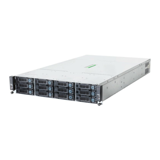
- Page 1 STRATOS S810 Series S810-X52LR Cluster-in-a-box Server High density 2U Shared Storage User's Guide Document Version: 1.0...
- Page 2 ONVENTIONS Conventions Several different typographic conventions are used throughout this manual. Refer to the following examples for common usage. Bold type face denotes menu items, buttons and application names. Italic type face denotes references to other sections, and the names of the folders, menus, programs, and files. <Enter>...
- Page 3 CRONYMS Acronyms EFINITION EFINITION A signal is deasserted when in the inactive state. Analog to Digital Active-low signal names have “_L” appended to the ACPI Advanced Configuration and Power Interface end of the signal mnemonic. Active-high signal names Deasserted have no “_L” suffix. To reduce confusion when referring Alerting Standard Forum to active-high and active-low signals, the terms one/ Active-high (positive true) signals are asserted when in...
- Page 4 CRONYMS EFINITION EFINITION IPMI Intelligent Platform Management Interface Unit of electrical resistance In-Target Probe Power Distribution Board 1024 bytes. Platform Event Filtering Keyboard Controller Style Platform Event Paging Keyboard, Video, Mouse PERR Parity Error Local Area Network Power-On Hours Liquid Crystal Display POST Power-On Self Test Lower Critical Threshold...
- Page 5 CRONYMS EFINITION Server Management Mode Server Management Software SNMP Simple Network Management Protocol Serial Over LAN UART Universal Asynchronous Receiver/Transmitter Upper Critical Threshold User Datagram Protocol UNCT Upper Non-Critical Threshold UNRT Upper Non-Recoverable Threshold Watchdog Timer Word 16-bit quantity...
-
Page 6: Important Safety Instructions
AFETY NFORMATION Safety Information Important Safety Instructions Hazardous conditions, devices and cables: Hazardous elec- trical conditions may be present on power, telephone, and com- munication cables. Turn off the server and disconnect the power cord, telecommunications systems, networks, and Read all caution and safety statements in this document before modems attached to the server before opening it. - Page 7 AFETY NFORMATION with the pliers, never the wide sides. Gripping the wide sides can damage the contacts inside the jumper, causing intermittent problems with the function controlled by that jumper. Take care to grip with, but not squeeze, the pliers or other tool used to remove a jumper, or the pins on the board may bend or break.
-
Page 8: Revision History
HAPTER PDATES Copyright Disclaimer Copyright © 2014 Quanta Computer Inc. This publication, The information in this document is subject to change without including all photographs, illustrations and software, is pro- notice. The manufacturer makes no representations or warran- tected under international copyright laws, with all rights ties with respect to the contents hereof and specifically dis- reserved. -
Page 9: About The Server
About the Server Chapter 1... - Page 10 BOUT THE ERVER NTRODUCTION 1.1. Introduction This manual is written for system technicians who are responsi- Configuration 1: ble for troubleshooting, upgrading, and repairing the server (1) PCIe x16 G3 slot for PCIe x8 riser card (supporting chassis. This document provides an overview of the hardware (1) mezzanine card and (1) PCIe low profile card) and features of the chassis, troubleshooting information, and (1) PCIe x16 G3 slot for expander linking board.
-
Page 11: Specifications
BOUT THE ERVER YSTEM EATURES Specifications SAS Controller LSI SAS controller Form Factor Quanta LSISAS 2008 mezzanine card (optional) X5 (2U chassis) Memory Net Weight 22.5kg (49.38lb) (16) DDR3 800/1066/1333/1600 MHz per node Chassis Size (L x W x H) Storage 774.7 mm x 447.0 mm x 87.3 mm... - Page 12 BOUT THE ERVER YSTEM EATURES (1) PCIe x16 G3 slot for PCIe x8 riser card supporting (1) (1) Quanta 10Gb SFP+ dual port mezzanine card expander linking board and (1) PCIe low profile card(*) (optional) (*) The internal boot disk will interfere with 3rd PCIe slot.
- Page 13 BOUT THE ERVER YSTEM EATURES Trusted Platform Module (TPM) Restriction of Hazardous Substances (RoHS) Intel Node Management Support System Management IPMI v2.0 Compliant, on board "KVM over IP" support...
-
Page 14: Package Contents
BOUT THE ERVER ACKAGE ONTENTS 1.2. Package Contents Package Contents Overview (Continued) ITEM EPE Cap Bottom CPU Heat Sinks Expander Kit Assembly EPE Cap Top Chassis Package Contents Overview Package Contents Overview ITEM Rail Kit Expander Kit Internal HDD Brackets... -
Page 15: A Tour Of The System
BOUT THE ERVER OUR OF THE YSTEM 1.3. A Tour of the System The following illustrations show the major component parts of Component Overview these two variants. ITEM DESCRIPTION System Sled (2) Mainboard sleds (2) Power supply units Chassis (1) X5-type system chassis HDD Assem- (12) Hot swappable 3.5”... -
Page 16: System Front View
BOUT THE ERVER YSTEM RONT System Front View Node Control Panels Node Front Panel Features System Front View System Front View FEATURE DESCRIPTION Front Panel (2) node control system HDD Bays 2.5” or 3.5” HDDs supported Node Front Panel Features Node Front Panel Features EATURE UNCTION... -
Page 17: System Rear View
BOUT THE ERVER YSTEM Node Front Panel Features (Continued) System Rear View Configuration 1 EATURE UNCTION FEATURE DESCRIPTION NODE 1 MB module 2 Mainboard (MB) module 2 NODE 1 module ID LED control ID Button PSU (top) Top power supply unit (PSU) NODE 2 MB module 1 Mainboard (MB) module 1... - Page 18 (2) Connection for USB devices System I/O Features Configuration 1 ICON EATURE ESCRIPTION Mini SAS port Connection for SAS device PCIe slot Slot for PCIe card Slot for Quanta made mezzanine Mezzanine slot card Power button with System power button with LED...
- Page 19 BOUT THE ERVER YSTEM Configuration 2 System I/O Features Configuration 2 (Continued) ICON EATURE ESCRIPTION Management port Management LAN access (BMC) COM Port Connection for COM devices VGA Port Connection for a monitor ID LED System identification LED USB Port (2) Connection for USB devices PCIe slot Slot for PCIe card...
-
Page 20: Power Subsystem
BOUT THE ERVER OWER YSTEM Power Sub-System Cooling Sub-System Fans may spin for some time after the system has been pow- ered off. Allow time for the fans to stop rotating before handling TOP PSU system components. MB 2 MB 1 BOTTOM PSU PSU to Mainboard Module Description WARNING! -
Page 21: Led Status Definitions
LED S BOUT THE ERVER TATUS EFINITIONS LED Status Definitions Control Panel LED LAN LED The system mainboard has one I350 or 82599EN (optional) Ethernet controller and two 1 GbE or one 10 GbE (optional) ports. Each RJ45 connector has two built-in LEDs. See the fol- lowing illustration and table for details. - Page 22 LED S BOUT THE ERVER TATUS EFINITIONS HDD LED Status Definitions (Continued) Control Panel LED Definitions HDD S TATUS CTIVITY EATURE UNCTION TATUS ESCRIPTION Blinking when activ- Green LED: Drive Rebuilding DC on NODE 1 Power Button On: 150 msec Green LED: Drive Failed DC off...
-
Page 23: Installation And Assembly Safety Instructions
Installation and Assembly Safety Instructions Chapter 2... -
Page 24: Installation Assembly Safety Instructions
NSTALLATION AND SSEMBLY AFETY NSTRUCTIONS NSTALLATION SSEMBLY AFETY NSTRUCTIONS 2.1. Installation Assembly Safety Instructions Guidelines The power supply in this product contains no user-serviceable parts. Refer servicing only to qualified personnel. Do not attempt to modify or use the supplied AC power cord if it is not the exact type required. A product with more than one power supply will have a separate AC power cord for each supply. - Page 25 NSTALLATION AND SSEMBLY AFETY NSTRUCTIONS UIDELINES SAFETY STEPS: Whenever you remove the chassis covers to access the inside of the system, follow these steps: 1. Turn off all peripheral devices connected to the system. 2. Turn off the system by pressing the power button. 3.
- Page 26 NSTALLATION AND SSEMBLY AFETY NSTRUCTIONS UIDELINES The system is designed to operate in a typical office environment. Choose a site that is: Clean and free of airborne particles (other than normal room dust). Well ventilated and away from sources of heat including direct sunlight. ...
-
Page 27: Safety Information
Safety Information Chapter 3... -
Page 28: Server Safety Information
AFETY NFORMATION ERVER AFETY NFORMATION 3.1. Server Safety Information Safety Warnings and Cautions To reduce the risk of bodily injury, electrical shock, fire, and equipment damage, read this document and observe all warn- ings and precautions in this guide before installing or maintain- ing your server product. -
Page 29: Intended Application Uses
AFETY NFORMATION NTENDED PPLICATION Intended Application Uses Indicates do not touch fan blades, may result in injury. This product was evaluated as Information Technology Equip- ment (ITE), which may be installed in offices, schools, computer Indicates to unplug all AC power cord(s) to discon- rooms, and similar commercial type locations. -
Page 30: Site Selection
AFETY NFORMATION ELECTION Site Selection Equipment Handling Practices The system is designed to operate in a typical office environ- Reduce the risk of personal injury or equipment damage: ment. Choose a site that is: Conform to local occupational health and safety require- ... -
Page 31: Power And Electrical Warnings
AFETY NFORMATION OWER AND LECTRICAL ARNINGS Power and Electrical Warnings CAUTION! HEN REPLACING A HOT PLUG POWER SUPPLY UNPLUG THE POWER CORD TO THE POWER SUPPLY BEING REPLACED BEFORE REMOVING IT FROM THE SERVER CAUTION! HE POWER BUTTON INDICATED BY THE STAND BY POWER MARK , DOES NOT CAUTION! -
Page 32: System Access Warnings
AFETY NFORMATION YSTEM CCESS ARNINGS System Access Warnings CAUTION! HE POWER SUPPLY CORD ARE THE MAIN DISCONNECT DEVICE TO POWER HE SOCKET OUTLET MUST BE NEAR THE EQUIPMENT AND READILY ACCESSIBLE FOR DISCONNECTION CAUTION! O AVOID PERSONAL INJURY OR PROPERTY DAMAGE THE FOLLOW ING SAFETY INSTRUCTIONS APPLY WHENEVER ACCESSING THE CAUTION! -
Page 33: Rack Mount Warnings
AFETY NFORMATION OUNT ARNINGS You are responsible for installing a main power disconnect for CAUTION! the entire rack unit. This main disconnect must be readily NLESS YOU ARE ADDING OR REMOVING A HOT PLUG COMPONENT accessible, and it must be labeled as controlling power to the ALLOW THE SYSTEM TO COOL BEFORE OPENING THE COVERS entire unit, not just to the server(s). -
Page 34: Other Hazards
(ESD) AFETY NFORMATION LECTROSTATIC ISCHARGE Other Hazards Reliable Earthing - Reliable earthing of rack-mounted equip- ment should be maintained. Particular attention should be given to supply connections other Battery Replacement than direct connections to the branch circuit (e.g. use of power strips). -
Page 35: Cooling And Airflow
AFETY NFORMATION THER AZARDS Cooling and Airflow CAUTION! AREFULLY ROUTE CABLES AS DIRECTED TO MINIMIZE AIRFLOW BLOCKAGE AND COOLING PROBLEMS OR PROPER COOLING AND AIRFLOW OPERATE THE SYSTEM ONLY WITH THE CHASSIS COVERS INSTALLED PERATING THE SYSTEM WITHOUT THE COVERS IN PLACE CAN DAMAGE SYSTEM PARTS O INSTALL THE COVERS Check first to make sure you have not left loose tools or... -
Page 36: Regulatory And Compliance Information
Regulatory and Compliance Infor- mation Chapter 4... -
Page 37: Electromagnetic Compatibility Notices
EGULATORY AND OMPLIANCE NFORMATION LECTROMAGNETIC OMPATIBILITY OTICES 4.1. Electromagnetic Compatibility Notices FCC Verification Statement Connect the equipment to an outlet on a circuit other than the one to which the receiver is connected. (USA) Consult the dealer or an experienced radio/TV technician ... -
Page 38: Europe (Ce Declaration Of Conformity)
(CE D EGULATORY AND OMPLIANCE NFORMATION UROPE ECLARATION OF ONFORMITY Europe (CE Declaration of Con- BSMI (Taiwan) formity) The BSMI Certification Marking and EMC warning is located on the outside rear area of the product This product has been tested in accordance too, and complies with the Low Voltage Directive (73/23/EEC) and EMC Directive (89/336/EEC). -
Page 39: Restriction Of Hazardous Sub- Stances (Rohs) Compliance
/ or stances (RoHS) Compliance take-back. ® Quanta Computer Inc. has a system in place to restrict the use of banned substances in accordance with the European Direc- tive 2002/95/EC. Compliance is based on declaration that... -
Page 40: Product Regulatory Compliance Markings
EGULATORY AND OMPLIANCE NFORMATION RODUCT EGULATORY OMPLIANCE ARKINGS 4.2. Product Regulatory Compliance Markings This product is marked with the following product certification Product Regulatory Compliance Markings (Continued) markings: Product Regulatory Compliance Markings BSMI Certifi- cation Num- R43039 EGULATORY Taiwan EGION ARKING ber &...
Need help?
Do you have a question about the STRATOS S810 Series and is the answer not in the manual?
Questions and answers