Sign In
Upload
Manuals
Brands
INVT Manuals
Inverter
Goodrive600 Series
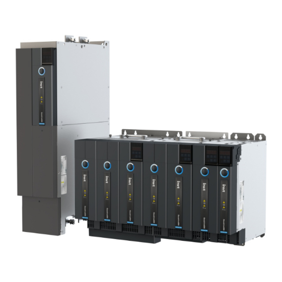
INVT Goodrive600 Series Drives Manuals
Manuals and User Guides for INVT Goodrive600 Series Drives. We have
2
INVT Goodrive600 Series Drives manuals available for free PDF download: Operation Manual
INVT Goodrive600 Series Operation Manual (424 pages)
High-perfomance Multifunction VFD
Brand:
INVT
| Category:
Inverter
| Size: 17 MB
Table of Contents
Preface
2
Table of Contents
3
Safety Precautions
9
What this Chapter Contains
9
Safety Definition
9
Warning
9
Safety Guidelines
10
Delivery and Installation
10
Commissioning and Running
11
Maintenance and Component Replacement
11
Disposal
12
Quick Startup
13
What this Chapter Contains
13
Unpacking Inspection
13
Checking before Use
13
Environment Checking
13
Checking after Installation
14
Basic Commissioning
14
Product Overview
15
What this Chapter Contains
15
Basic Principles
15
Specifications
17
Product Nameplate
19
Model Designation Code
20
Product Ratings
21
Structure
22
Installation
24
What this Chapter Contains
24
System Model Selection
24
Model Selection Flowchart
25
Load and Motor Selection
25
Inverter Unit Selection
25
Rectifier Unit Selection
25
Combined Arrangement
26
Mechanical Installation
28
Installation Environment
28
Installation Direction
29
Installation Method
29
Installation Backplane Design Requirements
30
Installation Space and Heat Dissipation
31
Bus Bar Connection
33
Bus Terminal Installation
35
Grounding Aluminum Bar Installation
36
AC Terminal Cover Disassembly and Assembly
36
Standard Wiring of the Main Circuit
37
Wiring Diagram of the Main Circuit
37
Terminal Diagram of the Main Circuit
38
Wiring Procedure
39
Safety Capacitor Jumper
40
Standard Wiring of the Control Circuit
41
Control Circuit Wiring Diagram of the Rectifier Unit
41
Control Circuit Terminal Diagram of the Rectifier Unit
41
Control Circuit Terminal Description of the Rectifier Unit
42
DIP Switch Function Description of the Rectifier Unit
43
Control Circuit Wiring Diagram of the Inverter Unit
44
Control Circuit Terminal Diagram of the Inverter Unit
45
Control Circuit Terminal Description of the Inverter Unit
45
DIP Switch Function Description of the Inverter Unit
47
Control Circuit Wiring Description
47
Wiring Protection
50
Protecting the VFD and Input Power Cable in Case of Short Circuit
50
Protecting the Motor and Motor Cable in Case of Short Circuit
51
Protecting the Motor against Thermal Overload
51
Bypass Connection
51
Basic Operation Guidelines
52
What this Chapter Contains
52
Keypad Introduction
52
Keypad Display
53
Displaying Stopped-State Parameters
53
Displaying Running-State Parameters
53
Displaying Fault Information
54
Editing Function Codes
54
Operating the VFD through the Keypad
54
Modifying the Function Codes of the Rectifier Unit
54
Setting the Password for the Rectifier/Inverter Unit
55
Viewing Rectifier/Inverter Unit Status
55
Rectifier Unit Basic Functions
55
Basic Information
55
Basic Function Parameter Settings
55
Start/Stop Control
57
Rectifier-Inverter Interaction
57
Protection against Networking Communication Faults
59
Digital Input
60
Relay Output
62
Communication Networking
63
Inverter Unit Basic Functions
63
What this Section Describes
63
Common Commissioning Procedure of the Inverter Unit
63
Vector Control
66
Space Voltage Vector Control Mode
71
Torque Control
77
Motor Parameter Autotuning
80
Start/Stop Control
85
Frequency Setting
88
Analog Input
91
Analog Output
92
Motor Temperature Detection
96
Digital Input
99
Digital Output
104
Simple PLC
108
Multi-Step Speed Running
109
PID Control
111
Run at Wobbling Frequency
115
Master/Slave Control
117
Commissioning Procedures for Closed-Loop Control, Position Control and Spindle Positioning
118
Fault Handling
123
Workshop Introduction
125
Communication Networking
126
What this Chapter Contains
126
Standard Communication Interfaces
126
Modbus Networking
126
Network Topology
126
RTU Mode
127
RTU Command Code and Communication Data
130
Data Address Definition
133
Fieldbus Scale
136
Error Message Response
137
Read/Write Operation Examples
138
Related Parameters
142
Canopen Bus Networking
144
Network Topology
144
Networking Description
145
Related Parameters
145
Canopen Protocol Introduction
148
Canopen Packet Format
148
NMT Command
149
NMT Node Guarding
150
Heartbeat Packet (Heartbeat Producer)
150
Start Packet (NMT Boot-Up)
151
Synchronous Packet Object (SYNC)
151
Emergency Packet Object (EMCY)
151
Service Data Object (SDO)
153
Process Data Object (PDO)
155
PROFIBUS-DP-To-Canopen Networking
164
PROFIBUS-DP Communication Protocol Introduction
164
Communication Packet Structure
165
Baud Rate and Communication Distance
165
Network Topology
166
Communication Performance
166
Commissioning Procedure
166
Related Parameters
179
PROFINET-To-Canopen Networking
187
PROFINET Communication Protocol Introduction
187
Communication Packet Structure
188
Network Topology
195
Communication Performance
196
Commissioning Procedure
197
Related Parameters
210
PROFIBUS-DP Bus Networking
218
Communication Packet Structure
218
Network Topology
219
Communication Performance
219
Commissioning Procedure
219
Related Parameters
221
PROFINET Bus Networking
225
Communication Packet Structure
225
Network Topology
225
Communication Performance
226
Commissioning Procedure
226
Related Parameters
228
Function Parameter List
236
What this Chapter Contains
236
Rectifier Function Parameter List
237
Inverter Function Parameter List
254
Troubleshooting
350
What this Chapter Contains
350
Indications of Alarms and Faults
350
Fault Reset
350
Rectifier Fault Reset
350
Inverter Fault Reset
350
Fault History
350
Faults and Solutions
350
Rectifier Faults and Solutions
350
Inverter Faults and Solutions
354
Other Status
360
Analysis on Common Faults
361
Motor Fails to Work
361
Motor Vibrates
362
Overvoltage
362
Undervoltage
363
Motor Overheating
363
Inverter Unit Overheating
364
Motor Stalls During ACC
364
Overcurrent
365
Countermeasures on Common Interference
365
Interference on Meter Switches and Sensors
365
Interference on Rs485/Canopen Communication
366
Failure to Stop and Indicator Shimmering Due to Motor Cable Coupling
367
Leakage Current and Interference on RCD
367
Live Device Chassis
368
Maintenance
369
Advertisement
INVT Goodrive600 Series Operation Manual (54 pages)
Brand:
INVT
| Category:
Controller
| Size: 1 MB
Table of Contents
Safety Precautions
2
Table of Contents
3
Product Confirmation
4
Product Overview
5
Basic Information
5
Model Description
5
Expansion Card Function Description
6
Secondary Development Platform
9
Auto Station Introduction
9
PLC Program Download Interface
9
How to Edit Programs on the Auto Station
10
Auto Station Programming Interfaces
14
Importing and Exporting Interfaces
14
Interfaces for Digital Inputs and Outputs
16
Interfaces for Control Commands and Function Commands
19
Interfaces for Setting Function Parameters
22
Interfaces for Viewing Function Parameters and VFD Status
24
PLC Card User-Defined Fault (10 Designed Currently) Interface
28
Interface for Writing Data
29
Interfaces for Monitoring PLC Card Data
30
RUN/STOP Switch and PLC Card Running Status
30
Dp/Canopen/Pn Communication Channel
32
Programming Cases
37
Appendix A D Elements for Exchange between the PLC Card and VFD
38
Appendix B List of Function Codes (in Group P27)
51
Advertisement
Related Products
INVT Goodrive3000 GD3000-01-090G-12
INVT Goodrive3000 GD3000-01-315G-12
INVT Goodrive3000 GD3000-01-500G-12
INVT Goodrive3000 GD3000-11-090G-12
INVT Goodrive3000 GD3000-11-110G-12
INVT Goodrive3000 GD3000-11-400G-12
INVT Goodrive170-PV Series
INVT Goodrive30 VFD Series
INVT Goodrive3000 GD3000-11-500G-12
INVT Goodrive3000 GD3000-11-630G-12
INVT Categories
Inverter
DC Drives
Servo Drives
Controller
UPS
More INVT Manuals
Login
Sign In
OR
Sign in with Facebook
Sign in with Google
Upload manual
Upload from disk
Upload from URL