
Subscribe to Our Youtube Channel
Related Manuals for probst POWERPLAN PP


Summary of Contents for probst POWERPLAN PP
- Page 1 51300001 POWERPLAN PP Screeding Machine Operating Instructions Translation of original operating instructions POWERPLAN PP Screeding Machine 5130.0011...
- Page 2 Bitte beachten Sie, dass das Produkt ohne vorliegende Betriebsanleitung in Landessprache nicht eingesetzt / in Betrieb gesetzt werden darf. Sollten Sie mit der Lieferung des Produkts keine Betriebsanleitung in Ihrer Landessprache erhalten haben, kontaktieren Sie uns bitte. In Länder der EU / EFTA senden wir Ihnen diese kostenlos nach.
-
Page 3: Table Of Contents
Operating Instructions 1 Contents Contents ................................. 2 EC-Declaration of Conformity ..........................5 Safety ..................................6 Information on these operating instructions ....................6 Hazard classification ............................6 The structure of the safety information provided in this manual ..............6 Description of symbols and warning signs ..................... 7 Overview of hazard symbols and information signs .................. - Page 4 Operating Instructions 5.2.2 Overview of the engine compartment ..................... 32 Daily inspections ............................. 33 5.3.1 Checking the fuel level ..........................33 5.3.2 Checking the engine oil level ........................34 5.3.3 Checking the hydraulic fluid level ......................35 5.3.4 Checking the coolant level ........................35 5.3.5 Cleaning the air filter ..........................
- Page 5 If the machine is not used for a longer period of time ................69 6.6.2 Disposal ..............................69 Repairing faults .............................. 70 Duty of inspection ............................72 Information on the type plate ........................73 6.10 Information on hiring out PROBST machinery ..................... 73 4 / 73...
-
Page 6: Ec-Declaration Of Conformity
DIN EN 60204-1 (IEC 60204-1) Safety of machinery – Electrical equipment of machines. Part 1: General requirements Authorised person for documentation: Name: J. Holderied Address: Probst GmbH; Gottlieb-Daimler-Str. 6; 71729 Erdmannhausen; Germany Signature, the undersigned: Erdmannhausen, 05.02.2020......................(Eric Wilhelm, Managing Director) -
Page 7: Safety
Operating Instructions Safety Safety Information on these operating instructions These operating instructions contain important information on how to properly and safely operate the screeding machine POWER PLAN PP and are intended for the following persons: • The machine owner • Assistants •... -
Page 8: Description Of Symbols And Warning Signs
Operating Instructions Safety Description of symbols and warning signs These operating instructions may contain any of the following symbols. Danger Failure to implement the measures needed to avoid this danger can lead to death, injury or damage. Dangerous electric voltage Failure to implement the measures needed to avoid this danger can lead to death, injury or damage as a result of high voltage. -
Page 9: Overview Of Hazard Symbols And Information Signs
Operating Instructions Safety Overview of hazard symbols and information signs 8 / 73... - Page 10 Operating Instructions Safety Designation Order number Specialist testing inspection plate 2904.0056 Type plate Attachment points for lifting gear 2904.0370 Joystick operating diagram 2904.0487 Main switch operating diagram 2904.0484 Driving direction front 2904.0552 / 2904.0553 Risk of crushing 2904.0220 (50 mm) Crawler chain tension information 2904.0554 Keep at a safe distance from the machine...
-
Page 11: Maintaining/Caring For Safety Symbols And Information Signs
• Meet the same requirements as assistants and operating personnel. • Have received corresponding training from Probst or a person authorised by Probst for performing the maintenance and inspection work described in these operating instructions. Personal safety Risk of personal injury and damage to property The machine must only be operated and maintained by qualified personnel! Failure to do so can lead to personal injury and damage to property. -
Page 12: Personal Safety Equipment
Operating Instructions Safety 3.7.1 Personal safety equipment Risk of personal injury Failure to wear corresponding personal safety equipment when working with/on the machine can lead to injury and damage to health. • Personnel must wear the corresponding personal safety equipment specified under the national regulations for the respective type of work they are performing. -
Page 13: Accident Prevention
Operating Instructions Safety All personnel must wear a face shield Failure to wear the required face shield can lead to face injuries. All personnel must wear a dusk mask Failure to wear the required dusk mask can cause damage to health. All personnel must wear breathing protection Failure to wear the required breathing protection can cause damage to health. -
Page 14: Hazard Zone
Operating Instructions Safety Hazard zone Risk of personal injury Operating the machine incorrectly can lead to injury and death. • When operating the machine and while its engine is running, only the operator and no more than one assistant are permitted inside the machine’s hazard zone. •... -
Page 15: Hydraulic Pipes And Connections
Operating Instructions Safety slopes, there is a risk that the machine may tip over. • Slopes with an incline of up to 12 % must only be descendent with an empty hopper and pointing straight forwards, and ascended pointing backwards. •... -
Page 16: Driving Mode
Operating Instructions Safety 3.11.1 Driving mode • To use driving mode, switch the machine to driving setting 0 or I. See “Driving settings and driving mode”. • Always leave the front chute down when using driving mode. • Always check the load bearing capacity of bridges, basement ceilings and roofs before driving onto them. •... - Page 17 Operating Instructions Safety building structures or the machine can lead to injury and even death. • Determine the safety distances to structures and observe them. 16 / 73...
-
Page 18: Maintenance
• Do not place any metal objects or tools onto the battery. • Only use original Probst spare parts and approved operating fluids. Failure to do so will void the warranty. • In winter, only fuel the machine using winter diesel. -
Page 19: Hydraulic Hoses And Pipes
Operating Instructions Safety Risk of personal injury Engine oil and hydraulic fluid can become hot and cause serious burns. • Unless stated otherwise, only perform maintenance and inspection work when the machine components are cool. • Always wear corresponding personal protective equipment such as acid-resistant gloves. Risk of personal injury Rotating parts can cause injuries. -
Page 20: Loading And Transporting The Machine
Operating Instructions Safety 3.16 Loading and transporting the machine. • Check the machine’s loading dimensions. • Check the transport vehicle’s permissible axle loads, wheel loads and permissible total load. • Take note of the dimensions and load bearing capacities of roads and bridges, as well as their overhead and side clearances. -
Page 21: General
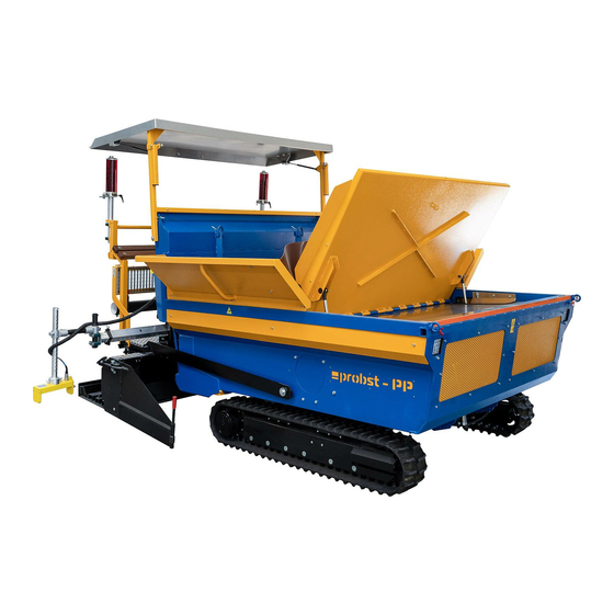
Operating Instructions General information General Correct use The Screeding Machine POWER PLAN PP is designed for creating a sub-base using different bedding materials. This could, for example, be aggregates and sand with grain sizes of 0-56 mm (#) or earth-moist concrete. Depending on the sub-base requirements, the sub-base’s height can be measured by ultrasound or laser. -
Page 22: Incorrect Use
The manufacturer does not accept warranty claims that arise from incorrect use, incorrect operation, insufficient maintenance or the use of unapproved operating fluids. Failure to use original Probst spare parts will void the warranty. When ordering spare parts or making claims under the warranty and/or for all other enquiries, please always state the machine type, machine number and year of manufacture. -
Page 23: Overview And Structure
Operating Instructions General information Overview and structure Smoothing board See “Raising/lowering the smoothing board” Holder for levelling board, shovel, etc. Measuring bar (folded) See “Overview of safety symbols and information signs”. Holder for MOBA laser receiver See separate operating tips in the section on “Laying and connecting the cable for the laser receiver”. -
Page 24: Training
Operating Instructions General information Main board See separate operating tips in the “Creating the sub-base” section. Tilt sensors The tilt sensors are used for detecting heights when using the ultrasound and laser technology. Fold open the measuring bar (1) by pulling it in the direction of the arrow. -
Page 25: Technical Data
Operating Instructions General information Technical data Model: POWER PLAN PP Drive power: 18,5 kW (25,2 HP) Engine: Diesel engine V1505-E4-B Please refer to the engine (KUBOTA) and combined cooler’s (EMMEGI) operating manuals for their technical data Cylinder capacity: 1.498 cm³ Equivalent permanent sound level LpA: 82 dB[A] Vibration values:... -
Page 26: Dimensions
Operating Instructions General information 4.7.1 Dimensions Total length 3665 mm Total height 2623 mm Height of the front chute when open 2089 mm Height up to the driver’s cab 1930 mm Height up to the hopper 1172 mm Opening angle of the front chute 60°... - Page 27 Operating Instructions General information Width of front chute 2090 mm Height up to the driver’s cab step 521 mm Width of the main board 2050 mm Width of the main board when extended with 2 extension boards 2750 mm Width of the main board when extended with 2 extension boards and 2 3450 mm smoothing boards Width with chutes folded out at the side...
-
Page 28: Operating The Machine
Operating Instructions Operating the machine Operating the machine Risk of personal injury and damage to property Failure to observe the instructions in the introductory sections of these instructions can lead to injury and damage. • The information provided in the “Safety” and “General information” sections in particular must be observed. -
Page 29: Driver's Cab
Operating Instructions Operating the machine Driver’s cab 5.1.1 Overview of the driver’s cab Joystick (for driving forwards, backwards and sideways) See “Steering”. See “MOBA control unit”. MOBA control unit Operating equipment and indicators See “Operating equipment and indicators”. EMERGENCY STOP button (3 x) Manual control unit See “Manual control unit”. - Page 30 Operating Instructions Operating the machine 5.1.2 Operating equipment and indicators Raise the smoothing board on the left Fuel indicator Oil pressure control light → See “Oil pressure control light”. Preignition indicator → See “Starting the engine”. Battery control light→ See “Battery control light”. Operating hours indicator Raise the smoothing board on the right Lower the smoothing board on the right...
- Page 31 Operating Instructions Operating the machine 5.1.3 Manual control unit The manual control unit can be fastened to the magnetic plates on both the right and left side of the driver’s cab. EMERGENCY STOP button Open/close the right hopper flap Direction correction for “Automatic”...
-
Page 32: Engine Compartment
Operating Instructions Operating the machine Engine compartment 5.2.1 Opening the engine hood Risk of personal injury Because of the weight of the front chute, there is a risk of injury when manually opening the engine hood. • The front chute must only be opened partway and with the help of another person. Opening the engine hood hydraulically Open the front chute (1). -
Page 33: Overview Of The Engine Compartment
Operating Instructions Operating the machine 5.2.2 Overview of the engine compartment Battery See “Maintaining the battery”. Main switch See “Main switch”. Dipstick for checking the oil level See “Checking the oil level”. Air filter See “Cleaning the air filter”. Throttle valve for adjusting the damper speed for the front See “Adjusting the damper speed for the front chute”. -
Page 34: Daily Inspections
Operating Instructions Operating the machine Daily inspections 5.3.1 Checking the fuel level Risk of damage to property The use of fuels that do not comply with the requirements of the European standard EN 590 can lead to increased wear and damage the engine. Do not use any of the following fuels: •... -
Page 35: Checking The Engine Oil Level
Operating Instructions Operating the machine 5.3.2 Checking the engine oil level Park the machine on level ground, switch it off and leave to cool for around 5 minutes. Open the engine hood. See “Opening the engine hood”. Pull out the dipstick (1) and clean with a lint-free, clean cloth. -
Page 36: Checking The Hydraulic Fluid Level
Operating Instructions Operating the machine 5.3.3 Checking the hydraulic fluid level Park the machine on level ground. Open the engine hood. See “Opening the engine hood”. Check the hydraulic fluid level at the fluid level indicator (1). Fluid level in the middle: Ideal fluid level. -
Page 37: Cleaning The Air Filter
Operating Instructions Operating the machine Park the machine on level ground. Open the engine hood. See “Opening the engine hood”. Carefully unscrew the cap (1) and allow the excess pressure to escape. 4. Carefully continue unscrewing the cap (1) and remove. If the coolant reaches up to the bottom lip of the filler pipe, the cooler contains sufficient cooler. - Page 38 Operating Instructions Operating the machine 4. Pull out the air filter (4). Blow dry, compressed air (max. 5 bar) into the inside of the air filter (4) until there is no longer any dust coming out of it. 6. Check each of the paper profiles for tears and holes using a suitable flashlight.
-
Page 39: Checking The Accelerator
Operating Instructions Operating the machine 5.3.6 Checking the accelerator Move the accelerator (1) to the left and right dead stop. The accelerator (1) must be easy to move. Before starting the machine 5.4.1 Main switch Risk of accident Failure to use the machine correctly and appropriately can lead to accidents - as can its use by authorized persons. -
Page 40: Operation
Operating Instructions Operating the machine Switching off the main switch Turn the lever (2) anticlockwise until it is in position (3) and remove. Switching on the main switch Insert the lever in position (3) and turn clockwise. 4. Flip back the headlight (1). Operation 5.5.1 Inspections to be performed before starting the engine... - Page 41 Operating Instructions Operating the machine Battery control light The battery control light (1) must be illuminated when the ignition switch is ① set to I. See the section on “Starting the engine“. When the engine is running, this control light must extinguish. If it does not, there is a fault.
-
Page 42: Starting The Engine
Operating Instructions Operating the machine Operating hours indicator To observe the specified operating-hour ① based maintenance intervals, they must be regularly checked at the operating hours indicator (1). 5.5.2 Starting the engine Risk of personal injury Sudden machine movements can lead to injuries. •... -
Page 43: Controlling Engine Speed
Operating Instructions Operating the machine If the machine is in automatic mode, it will make a signal sound. Push the toggle switch (2) down. 6. Push the toggle switch (2) up. The Screeding Machine POWER PLAN PP is now ready to be driven. Risk of damage to property If the warning lights fail to extinguish, there is a fault. -
Page 44: Adjusting The Damper Speed For The Front Chute
Operating Instructions Operating the machine 5.5.4 Adjusting the damper speed for the front chute Depending on the operating method and operator’s speed, the damper speed of the front chute can either be increased or reduced. Throttle valve (1) = Raises the front chute. Throttle valve (2) = Lowers the front chute. - Page 45 Operating Instructions Operating the machine Manual driving mode ① Switch toggle switch (1) to 0. Automatic driving mode Switch toggle switch (1) to 0. Switch toggle switch (2) to I. Switch toggle switch (4) on the manual control unit on. See “Manual control unit”.
-
Page 46: Starting To Drive
Operating Instructions Operating the machine 5.5.6 Starting to drive Risk of accident Lack of attention when starting to drive the machine in driving mode can lead to accidents. • In the event of danger, warn people accordingly using hand signals. •... -
Page 47: Fitting/Removing The Smoothing And Spreading Board
Operating Instructions Operating the machine Undo the wing screw (1). Pull out the chain guide (2) to the required length. Let the chain (3) drop. 4. Tighten the wing screw (1). 5.5.8 Fitting/removing the smoothing and spreading board The smoothing and spreading board can be attached on the left and right side of the machine. Fitting the boards Put the spreading board (1) into position and lock the fasteners (2). -
Page 48: Adjusting The Adjustable Panels
Operating Instructions Operating the machine 5.5.9 Adjusting the adjustable panels The adjustable panels are located on the left and right side of the machine. Pull out the lock bolt (1) and turn. Move the adjustable panel (2) into the required position. A detailed description of how the adjustable panel can be adjusted during operation can be found in the... -
Page 49: Switching The Machine Off
Operating Instructions Operating the machine 5.5.11 Switching the machine off Park the machine on solid and even ground. If parked on an incline, protect the machine from moving. Fully lower the smoothing board. See “Raising/lowering the smoothing board” 4. Switch off the engine. Switch off the electrical system at the main switch. -
Page 50: Preparing The Machine For Transport
Operating Instructions Operating the machine 5.6.2 Preparing the machine for transport Completely empty the hopper. Collapse the adjustable panels. See “Adjusting the adjustable panels”. Fold up the sideway extensions of the chutes. 4. Take down the smoothing and spreading board. See “Fitting the smoothing and spreading board”. -
Page 51: Loading And Transporting The Machine
Operating Instructions Operating the machine 5.6.4 Loading and transporting the machine. Risk of accident If the machine is driven onto the transport vehicle pointing forward and the angle of the ramps is too step, there is a risk of accidents. •... - Page 52 Operating Instructions Operating the machine Lashing eyes Risk of accident Failure to tie down the machine can lead to accidents. • Tie down the machine at the specified lashing eyes to prevent it from sliding around on the platform and from tilting over. Tie the machine to the 4 lashing eyes (1) using chain tensionrs or tension elts.
-
Page 53: Lifting The Machine
Failure to lift the machine without or without suitable lifting gear can lead to injury and damage. • The machine must only be lifted with suitable and adequately dimensioned lifting gear at the lifting eyes described below. Suitable lifting gear can be obtained and ordered from Probst. • The stated chain lengths must be observed. •... -
Page 54: Maintenance And Care
Only use original spare parts and approved operating fluids. Failure to do so will void the warranty. • Probst only accepts warranty claims if the machine has been maintained as specified. See the enclosed maintenance record. Always include a copy of the maintenance record when making a claim under warranty. -
Page 55: Maintenance Intervals
Operating Instructions Maintenance and care Maintenance intervals Mechanical components Maintenance interval Maintenance work to be performed First inspection after 50 ● Check all fastening screws and retighten if necessary. Observe the tightening torques. operating hours Every 50 operating hours • Retighten all fastening screws. -
Page 56: Maintenance Plan
Operating Instructions Maintenance and care Maintenance plan Regular maintenance operations Also the service intervals of the separate operating manual for the engine (KUBOTA), the combination cooler (EMMEGI) and the crawler undercarriage (TFW) must absolutely be observed. Maintenance work Before each After the first Every Every... -
Page 57: Cleaning
Operating Instructions Maintenance and care Cleaning Risk of personal injury Cleaning the machine when it is at operating temperature can lead to serious injury. • Only clean the machine with the engine switched off and once all components have cooled down. -
Page 58: Dry-Cleaning With Compressed Air
Operating Instructions Maintenance and care 6.3.1 Dry-cleaning with compressed air Only dry-clean the machine with compressed air if it is only lightly soiled with dry dust. 6.3.2 Cleaning the machine with water and detergents If the machine is only lightly soiled with dust, oil and fuel: •... -
Page 59: Lubricating
Operating Instructions Maintenance and care Lubricating • For maintenance intervals, see “Maintenance plan”. • Thoroughly clean the lubrication points. • Keep adding lubricant until it starts to exit from the relevant openings. See “Technical data” for information on operating fluids and filling capacities. 58 / 73... -
Page 60: Maintenance Work
Changing the engine oil and oil filter The first oil and oil filter change is due after the first 50 operating hours and must be performed by Probst customer services. Thereafter, the oil and oil filter must be changed every 200 operating hours. -
Page 61: Maintaining The Crawler Tracks
Operating Instructions Maintenance and care Open the engine hood. See “Opening the engine hood”. Press onto the v-belt (1) with your thumb. The v-belt should give by about 7-9 mm (A) when pressed down. If necessary, get the v-belt tensioned by customer services. - Page 62 Operating Instructions Maintenance and care Figure A1 Tensioning/loosening the crawler chain Loosening Unscrew the cover panel (1). Keep unscrewing the valve (2) until lubricant starts to exit. Allow lubricant to exit until (A) has reached the correct dimensions. 4. Tighten the valve (2). Tightening torque 40-60 Nm.
-
Page 63: Maintaining The Battery
Operating Instructions Maintenance and care 6.5.7 Maintaining the battery Risk of personal injury Battery fumes, which are created in particular when charging batteries, are explosive and can therefore lead to injuries. • Keep the battery away from sparks and open flames. •... - Page 64 Operating Instructions Maintenance and care Connecting and disconnecting the battery Risk of personal injury There is a risk of short circuiting and sparking when connecting and disconnecting the battery. • Only connect and disconnect the battery if the electrical system has been switched off at the main switch.
- Page 65 Operating Instructions Maintenance and care Charging the battery Risk of personal injury and damage to property Failure to properly charge empty or frozen batteries can lead to injury and damage. • Empty batteries can already start to freeze at temperatures of -10 °C. •...
- Page 66 Operating Instructions Maintenance and care Open the engine hood. See “Opening the engine hood”. Remove the protective cap from the positive terminal. Connect the positive lead (1) to the positive terminal on the second battery. 4. Connect the positive lead (1) to the positive terminal (2).
-
Page 67: Changing Fuses
Operating Instructions Maintenance and care 6.5.8 Changing fuses Risk of damage to property Faulty fuses can cause damage to the electrical system. • Repair the fault that damaged the fuse. • Replace the fuse immediately and make sure that the new fuse has the right amps. •... - Page 68 Operating Instructions Maintenance and care Fuse assignment diagram Consumer Fuse rating Top terminal box Control voltage (ignition switch) 25 A Glow plugs 25 A Control voltage (downstream of ignition switch) 25 A Starter motor 25 A Lifting magnet 7.5 A Diesel pump 7.5 A Lights...
-
Page 69: Changing Light Bulbs
Operating Instructions Maintenance and care 6.5.9 Changing light bulbs Risk of personal injury and damage to property Light bulbs and lamp holders become hot when the lights are switched on. They can cause burns if touched and can ignite flammable objects. •... -
Page 70: If The Machine Is Not Used For A Longer Period Of Time / Disposing Of The Machine
Operating Instructions Maintenance and care If the machine is not used for a longer period of time / disposing of the machine 6.6.1 If the machine is not used for a longer period of time If the machine will not be used for more than 2 months: •... -
Page 71: Repairing Faults
Operating Instructions Maintenance and care Repairing faults Risk of personal injury and damage to property Faults can lead to injury and damage. • If there is a fault, stop the machine as quickly as possible and make it safe. • Establish the cause of the fault and repair it immediately. - Page 72 Operating Instructions Maintenance and care Fault Cause Remedy manual control unit is set to unit to “Automatic”. See “Drive settings and STOP. driving mode”. • ● Hydraulic pump makes Contact customer services. Hydraulic pump defective. noises. • ● Hydraulic system too hot. Check the hydraulic fluid level and top up if Hydraulic fluid level too low.
-
Page 73: Duty Of Inspection
This inspection must be documented in writing. • Probst recommends attaching the specialist testing inspection plate in a clearly visible place on the machine once the inspection has been completed and any faults repaired. See “Overview of safety symbols and information signs”. Label 1. -
Page 74: Information On The Type Plate
6.10 Information on hiring out PROBST machinery All PROBST machinery must be supplied with the associated original operating instructions if hired out. If the instruction manual’s language differs from the language of the relevant country of use, the original operating instructions must be translated into the relevant language and the translation supplied with the machinery. - Page 76 2749 Zusatzpaket (nicht im Standard enthalten) additional packet (not include in the standard) 2202 Zusatzpaket (nicht im Standard enthalten Art. Nr.: 41300109 - Rundumleuchte, gelb, turning light, yellow additional packet (not include in the standard) 2090 Art. Nr.: 41300004 - Fahrerschutzdach, driver protection roof Zusatzpaket (nicht im Standard enthalten) additional packet (not include in the standard) Art.
- Page 77 Ansichten ohne Zusatzpakete 3613 view without additional packet 2749 2090 2202 1900 1564 404,5 3450 Seitenansicht Heckansicht Frontansicht side view rear view front view Technische Spezifikationen: technical specifications: Technische Spezifikationen / Technische Spezifikationen / technical specifications: Hydraulik: Antrieb Fahrschiffe hydraulic: drive crawler chassis technical specifications: Power Plan: Tandem- Axialkolbenverstellpumpe...
- Page 78 3x NOT-STOP- TASTER / NOT-STOP pushbutton Bedien- Anzeigelemente / operator control- display elements MOBA- Controller / MOBA- Controller Arbeitsscheinwerfer / working headlights Motordrehzahlgulierung / engine speed regulation Hauptbohle / Bedienerstand / main plank / user-standing Fahr- Bedienhebel / moving-use lever Umschalthebel Bohle Schwimmstellung / Bohle anheben Lift the reversing lever plank floating position / board Handbediengerät / manual control device...
- Page 79 Allgemeintoleranzen nach DIN ISO 2768c Oberflächen nach DIN ISO 1302 allgemeiner Biegehalbmesser = Blechstärke Bei Änderungen Rücksprache mit TB ! Maßstab: 1:15 Gewicht: Oberflächen- Format 1:20 2433,3 kg behandlung Schutzvermerk nach DIN 34 beachten! Nachdruck nur mit unserer Genehmigung! Datum Name Benennung Flächenfertiger Power Plan...
- Page 81 41300109 41300004 siehe separate Liste see separate list 41300005 20060001 33100105 41300006 30300243 siehe separate Liste see separate list siehe Hydraulikschaltplan see circuit diagramm 41300079 41300207 siehe separate Liste see separate list 41300026 siehe separate Liste see separate list 41300106 41300061 siehe separate Liste siehe separate Liste...
- Page 82 41300068 41300069 21650001 20040004 41300073 20020012 20540024 21600014 20400003 20100016 20000060 21730009 20400003 20100015 20400002 20540033 21070062 21070015 20450006 20000016 20100017 20440006 33100114 20440006 20000069 © all rights reserved conform to ISO 16016 Datum Name Benennung Fahrerschutzdach, abklappbar, Erst. 17.3.2011 M.Kaltenbach demontierbar für Flächen- Gepr.
- Page 83 24030022 24030022 © all rights reserved conform to ISO 16016 Datum Name Benennung Laser-Kit Erst. 25.2.2011 M.Kaltenbach Laser-Empfänger-Ergänzung Gepr. 18.7.2017 I.Krasnikov für Flächenfertiger PP Artikelnummer/Zeichnungsnummer Blatt E41300006 Zust. Urspr. Ers. f. Ers. d.
- Page 84 20060023 33503252 20530003 41300039 41300040 33503251 33510001 20200001 D (1 : 2) C (1 : 2) 41300041 41300046 21610013 21610014 33100106 20100014 31600017 21610014 33100106 20540040 21050149 21050148 41300050 © all rights reserved conform to ISO 16016 20060016 Datum Name Benennung Vormontage von kompletter Abzieheinheit Erst.
- Page 85 41300199 41300038 41300198 41300037 20000065 20100017 41300095 20400058 41300197 20100017 22210006 siehe Hydraulikschaltplan see hydraulic circuit diagram 41300094 33100105 20540018 20000027 41300113 30300243 © all rights reserved conform to ISO 16016 Datum Name Benennung Vormontage von kompletter Abzieheinheit Erst. 8.3.2011 M.Kaltenbach für Flächenfertiger PP 41300094...
- Page 86 20020064 21050149 20020052 20020009 21070009 21050101 41300055 G (1 : 5) 20000048 41300211 20090049 21050146 E (1 : 5) 20540010 20000004 10100384 41300033 41300036 20030011 F (1 : 5) © all rights reserved conform to ISO 16016 Datum Name Benennung 41300034 Vormontage von kompletter Abzieheinheit Erst.
- Page 87 I (1 : 5) 20000028 20100017 20100019 H (1 : 5) 20000009 20450007 20440010 20400002 33100108 33503261 33504031 41300051 33100113 20400004 20000067 33100110 41300030 41300048 33100107 20440010 20000010 20480002 20000095 20540033 20000066 20400004 J (1 : 5) 33100105 21050054 30300242 20440005 21050117 20000061...
- Page 88 20040004 21600005 33503228 33100117 20040005 20530012 41300009 33503228 30320136 41300052 20000126 21060002 33100013 20540024 41300020 20440005 20100017 20440006 41300017 33100116 20440006 20000067 20100017 41300008 20400004 20000017 20000126 20400003 20000073 41300015 20400004 41300010 21060002 © all rights reserved conform to ISO 16016 Datum Name Benennung...
- Page 89 21600005 33100117 20530012 41300013 30320136 20040004 20440006 20000067 20040004 33100116 41300017 20000126 20440006 20000073 21060002 20100017 33100013 41300024 33503228 20540024 20400004 41300017 20400004 20100017 20000126 41300011 20000126 21060002 41300016 41300018 41300052 © all rights reserved conform to ISO 16016 Datum Name Benennung Vormontage von kompletter Abzieheinheit...
- Page 90 20400011 22160056 20400039 30300021 20530014 22210073 Bei Änderungen Rücksprache TB ! Gewicht: 7,8 kg Schutzvermerk nach DIN 34 beachten! Nachdruck nur mit unserer Genehmigung! Benennung Datum Name HD-Zylinder vormontiert für Erst. 24.2.2011 M.Kaltenbach Bunkerklappe an Flächen- Gepr. fertiger PP Blatt Artikelnummer/Zeichnungsnummer E41300106 Kunde:...
- Page 91 41300099 33504030 41300097 41300098 20400002 20000009 41300027 41300032 20000002 20400001 20100014 20190026 20040021 41500034 33503542 20040043 20450005 20000009 41300107 siehe separate Liste 41300038 see separate list 20440004 24300018 33700708 20100016 27230009 20000002 41300060 20040003 20400001 33700541 41300067 siehe separate Liste 41300105 see separate list ©...
- Page 92 41300031 20190010 20000018 20450006 41300062 41300107 41300206 siehe separate Liste see separate list K (1 : 6) 41300058 siehe separate Liste see separate list 41500489 26110110 20000013 33503528 20000009 36390010 20400002 20400002 20100015 20000012 20450005 20440004 33500064 20000013 20450005 20440006 25000006 20450007 25050001...
- Page 93 41300078 41300077 siehe separate Liste see separate list Bei Änderungen Rücksprache TB ! Gewicht: 33,2 kg Schutzvermerk nach DIN 34 beachten! Nachdruck nur mit unserer Genehmigung! Benennung Datum Name Komplette Elektrik zu Flächen- Erst. 30.7.2014 M.Kaltenbach fertiger PP Gepr. 30.7.2014 M.Kaltenbach bestehend aus: Blatt...
- Page 94 24030015 24110152 24300003 (ab Fgst. Nr.: PP 143) 24110159 24300005 24300004 24030016 24110152 (ab Fgst. Nr.: PP 143) 24110159 24110071 24110071 24110124 24110071 24900014 26990004 Bei Änderungen Rücksprache TB ! Gewicht: 18,0 kg Schutzvermerk nach DIN 34 beachten! Nachdruck nur mit unserer Genehmigung! Benennung Datum Name...
- Page 95 21600016 41300066 24110117 siehe Hydraulikschaltplan see circuit diagramm Art. Nr.: 41900119 (Standard PP) Art. Nr.: 41900118 (PP mit Außenrüttler) Bei Änderungen Rücksprache TB ! Gewicht: 4,2 kg Schutzvermerk nach DIN 34 beachten! Nachdruck nur mit unserer Genehmigung! Benennung Datum Name Vorsteuereinheit, vormontiert Erst.
- Page 96 41500536 26990011 20000018 20400003 22100007 33250007 21550011 20400003 41500550 41500487 26900035 siehe Hydraulikschaltplan see circuit diagramm 22100005 21570001 © all rights reserved conform to ISO 16016 Datum Name Benennung Hydrauliktank,vormontiert, Erst. 30.8.2011 M.Kaltenbach für Flächenfertiger PP Gepr. 18.7.2017 I.Krasnikov Artikelnummer/Zeichnungsnummer Blatt E41300058 Zust.
- Page 97 41500578 26100036 siehe separate Liste 20450006 see separate list 20000011 20000017 20000119 20450006 20450006 20000011 21050079 41300042 20100015 21070001 20000301 26130002 20450006 21050079 20000059 26920020 20440019 21050079 20460015 20000011 20100015 20020121 20000011 10100191 20000006 20000017 22600056 siehe Hydraulikschaltplan 20000049 20000301 see circuit diagramm 21050058 20450006...
- Page 98 41300104 21200017 20020146 20020050 21200015 © all rights reserved conform to ISO 16016 Datum Name Benennung Fahrwerk vormontiert für Erst. 25.2.2011 M.Kaltenbach Flächenfertiger PP Gepr. 18.7.2017 I.Krasnikov A (1 : 5) Artikelnummer/Zeichnungsnummer Blatt E41300026 Zust. Urspr. Ers. f. Ers. d.
- Page 100 Bedienungs - Operating and Instructions de service maintenance et entretien Wartungsanweisung instructions Ersatzteilliste Spare parts list Catalogue de pièces Serie - Nr. 1354-17 Serial - nr. N° de série Fahrantrieb Typ Track drive type Engrenage de chenille 702C2K - MAG 26VP- 4 702C2K - MAG 26VP- 4 702C2K - MAG 26VP- 4 Bauklasse 1.7 - 2.7...
- Page 101 BEDIENUNGSANLEITUNG OPERATING INSTRUCTIONS INSTRUCTION DE SERVICE TFW - FAHRTECHNIK AG Taf. Fig. Bedienung Operation Utilisation Plan. Bedienungs - Informationen Operating instructions Instructions de entretien 00.10.010 Aufbau, Benennung Construction and naming Safety Construction et dénomination 00.10.040 measures Mesures de sécurité Sicherheitsmaßnahmen 00.10.080 Prevention of accidents Prévention des accidents...
- Page 102 BEDIENUNGSANLEITUNG OPERATING INSTRUCTIONS INSTRUCTION DE SERVICE TFW - FAHRTECHNIK AG Mit allen zur Bedienung First familiarise yourself with Pour se familiariser avec notwendigen Informationen all the information you need toutes les informations vertraut machen to operate the equipment nécessaires pair l'utilisation •...
- Page 103 BEDIENUNGSANLEITUNG OPERATING INSTRUCTIONS INSTRUCTION DE SERVICE TFW - FAHRTECHNIK AG Aufbau, Benennung Construction, naming and Construction, dénomination und Verwendungszweck purpose of the undercarriage et finalité du train de chenille des Raupenfahrwerkes © Copyright by TFW - Fahrtechnik Serie - Nr. Serial - nr.
- Page 104 BEDIENUNGSANLEITUNG OPERATING INSTRUCTIONS INSTRUCTION DE SERVICE TFW - FAHRTECHNIK AG Sicherheitsmaßnahmen Safety measures for Mesures de sécurité pour general use of the track l'emploi général des trains beim allgemeinen Einsatz chains des chenilles von Raupenfahrwerken © Copyright by TFW - Fahrtechnik •...
- Page 105 BEDIENUNGSANLEITUNG OPERATING INSTRUCTIONS INSTRUCTION DE SERVICE TFW - FAHRTECHNIK AG Unfallverhütungs- Safety measures Mesures pour Massnahmen beim Einsatz when working lévitation des von Raupenfahrwerken with crawler machines accidents • Unachtsamkeit ist die häufigste • Lack of attention is the main ac- •...
- Page 106 BEDIENUNGSANLEITUNG OPERATING INSTRUCTIONS INSTRUCTION DE SERVICE TFW - FAHRTECHNIK AG Vorsichtsmaßnahmen Safety measures Mesures de sécurité beim Einsatz von when working with dans l'emploi des Gummiraupenbänder rubber tracks bandes en caoutchouc • Vermeiden Sie das Überfahren • Avoid passing over sharp mate- •...
- Page 107 BEDIENUNGSANLEITUNG OPERATING INSTRUCTIONS INSTRUCTION DE SERVICE TFW - FAHRTECHNIK AG Kippgefahr beim Fahren There is a risk of overturning Risque de renversement an Hängen beachten when travelling on slopes en cas conduite sur pentes Parken an Hängen Parking on slopes Arrêt sur pentes ©...
- Page 108 BEDIENUNGSANLEITUNG OPERATING INSTRUCTIONS INSTRUCTION DE SERVICE TFW - FAHRTECHNIK AG Aufladen des Gerätes Loading on to transport Charge d'une machine mit Raupenfahrwerk machine with crawler tracks sur chenilles © Copyright by TFW - Fahrtechnik • • Ramps width to be at least •...
- Page 109 BEDIENUNGSANLEITUNG OPERATING INSTRUCTIONS INSTRUCTION DE SERVICE TFW - FAHRTECHNIK AG Transport des Gerätes Machine- / vehicle Transport de la machine mit Raupenfahrwerk Transport sur chenilles • Maximale Höhe (A): je nach • Maximum height (A): depends • Hauteur max. (A): selon la Transportstellung des Gerätes, on machine' s transport posi- position de transport et...
- Page 110 BEDIENUNGSANLEITUNG OPERATING INSTRUCTIONS INSTRUCTION DE SERVICE TFW - FAHRTECHNIK AG Abladen des Gerätes Unloading of a machine Décharge d'une mit Raupenfahrwerk with crawler tracks machine sur chenilles © Copyright by TFW - Fahrtechnik • Ladeflächen und Rampen wie • Secure surfaces and ramps as •...
- Page 111 BEDIENUNGSANLEITUNG OPERATING INSTRUCTIONS INSTRUCTION DE SERVICE TFW - FAHRTECHNIK AG Sicherheitsanweisungen Safety instructions Instructions de Sécurité Standsicherheit Ensure stability Stabilité • Erst die Wartungsanweisung • First read the maintenance • Lire les instructions avant de lesen, dann die Wartungsarbeit instructions, then perform réaliser les travaux.
- Page 112 BEDIENUNGSANLEITUNG OPERATING INSTRUCTIONS INSTRUCTION DE SERVICE TFW - FAHRTECHNIK AG Raupenkette / Raupenband Checking rubber - or steel Contrôle de la Spannung kontrollieren crawler tension chaîne / bande In den ersten 50, und Check after the first 50 and then remière inspection Chaque p ...
- Page 113 BEDIENUNGSANLEITUNG OPERATING INSTRUCTIONS INSTRUCTION DE SERVICE TFW - FAHRTECHNIK AG Raupenkette / Raupenband Loosening Detensionner la lockern crawler track chaîne / bande © Copyright by TFW - Fahrtechnik • Deckel (1) abschrauben. • Unscrew cover (1). • Dévisser couvercle (1). •...
- Page 114 BEDIENUNGSANLEITUNG OPERATING INSTRUCTIONS INSTRUCTION DE SERVICE TFW - FAHRTECHNIK AG Raupenkette / Raupenband Tension rubber - or steel Comment tensionner la spannen crawler track chaîne / bande ou caoutchouc © Copyright by TFW - Fahrtechnik • Deckel (1) abschrauben. • Unscrew cover (1). •...
- Page 115 BEDIENUNGSANLEITUNG OPERATING INSTRUCTIONS INSTRUCTION DE SERVICE TFW - FAHRTECHNIK AG Federspannpaket Tension unit Dispositif de serrage Kontroll - und check up and Instructions de contrôle Wartungs - Informationen maintenance instructions et entretien. Spannrichtung Tension Range Direction de tension © Copyright by TFW - Fahrtechnik •...
- Page 116 BEDIENUNGSANLEITUNG OPERATING INSTRUCTIONS INSTRUCTION DE SERVICE TFW - FAHRTECHNIK AG Ölstand kontrollieren Check oil level Contrôler niveau d'huile alle 250 Betriebsstunden every 250 operating hours. chaque 250 heures de travail Füllhöhe Level Niveau • Verschluss-Schraube (2) • Unscrew plug (2). •...
- Page 117 BEDIENUNGSANLEITUNG OPERATING INSTRUCTIONS INSTRUCTION DE SERVICE TFW - FAHRTECHNIK AG Fahrantrieb Ölwechsel Travel gear renewing oil Echange d'huile engrenage planétaire chaque 1000 heures alle 1000 Betriebsstunden every 1000 operating hours Protégez l'environnement Umweltschutz beachten Protect environment • Spätestens jedoch nach •...
- Page 118 BEDIENUNGSANLEITUNG OPERATING INSTRUCTIONS INSTRUCTION DE SERVICE TFW - FAHRTECHNIK AG Schraubensitz Checking firm seating Contrôler kontrollieren of screws serrage des vis © Copyright by TFW - Fahrtechnik • Befestigungsschrauben der bei- • Check attachment for both drive • Contrôler les vis (7) des deux den Antriebskränze (7) kon- sprockets (7): jante dentée:...
- Page 119 ERSATZTEILLISTE SPARE PARTS LIST CATALOGUE DE PIECES TFW-FAHRTECHNIK AG Ersatzteilliste Spare parts list Catalogue de pièces © Copyright by TFW - Fahrtechnik • Bestellbeispiel: • Specimen order: • Exemple de commande: • (Bildtafel 17.30.003, Pos. N° 8) • (Fig. No.17.30.003,Pos. No° 8) •...
- Page 120 ERSATZTEILLISTE SPARE PARTS LIST CATALOGUE DE PIECES TFW-FAHRTECHNIK AG BEST. NR. BENENNUNG DESCRIPTION DESIGNATION BEMERKUNG ORD. NO. REMARK, REMARQUE 1220.113 FAHRWERK UNDERCARRIAGE TRACTION A CHENILLE POS.1 - 3 KOMPLETT COMPLETE COMPLET RAUPENFAHRWERK TRACK ASSEMBLY TRACTION A CHENILLE BONFIGLIOLI 17.30.003 /1 6 - ROLLIG 6 - ROLLER TYPE 6 - POULIE TYPE...
- Page 121 ERSATZTEILLISTE SPARE PARTS LIST CATALOGUE DE PIECES TFW-FAHRTECHNIK AG BEST. NR. BENENNUNG DESCRIPTION DESIGNATION BEMERKUNG ORD. NO. REMARK, REMARQUE 1171.061 FAHRSCHIFF TRACK SIDEFRAME TRACTION A CHENILLE POS. 1 - 17 KOMPLETT LINKS COMPLETE LEFT COMPLETE GAUCHE 1171.062 FAHRSCHIFF TRACK SIDEFRAME TRACTION A CHENILLE POS.
- Page 122 BEDIENUNGSANLEITUNG OPERATING INSTRUCTIONS INSTRUCTION DE SERVICE TFW - FAHRTECHNIK AG © Copyright by TFW - Fahrtechnik Best. NR. BENENNUNG DESCRIPTION DESIGNATION BEMERKUNG ORD. NO. REMARK, REMARQUE 1002.010 LAUFROLLE KPL. ROLLER CPL. POULIE COMPLETE REF. 1001.02 POS. 1 - 7 1002.600 DECKSCHEIBE WASHER RONDELLE...
- Page 123 ERSATZTEILLISTE SPARE PARTS LIST CATALOGUE DE PIECES TFW-FAHRTECHNIK AG © Copyright by TFW - Fahrtechnik BEST. NR. BENENNUNG DESCRIPTION DESIGNATION BEMERKUNG ORD. NO. REMARK, REMARQUE 1004.010 LEITRAD IDLER ROUE DE GUIDAGE POS. 1 - 9 1019.502 SPANNHUELSE ADAPTOR SLEEVE DOUILLE DE SERRAGE 10 x 50 1004.500 LAGERBOCK...
- Page 124 ERSATZTEILLISTE SPARE PARTS LIST CATALOGUE DE PIECES TFW-FAHRTECHNIK AG © Copyright by TFW - Fahrtechnik BEST. NR. BENENNUNG DESCRIPTION DESIGNATION BEMERKUNG ORD. NO. REMARK, REMARQUE 1135.004 SPANNPAKET KPL. ADJUSTING DISPOSITIV DE SERRAGE Kl. 1.7 / Pos. 1 - 8 DEVICE 1018.606 SICH.
- Page 125 ERSATZTEILLISTE SPARE PARTS LIST CATALOGUE DE PIECES TFW-FAHRTECHNIK AG POS. BEST. NR. BENENNUNG DESCRIPTION DESIGNATION BEMERKUNG ORD. NO. REMARK, REMARQUE 1007.135 FAHRANTRIEB KPL. TRACK GEAR CPL. ENGRENAGE PLANETAIRE POS. 1 - 3 WITH AVEC HYDRAULIK-MOTOR HYDRAULIC MOTOR MOTEUR HYDRAULIQUE AND COUNTER BALANCE VALVE SECTION DE SOUPAPE FAHR - BREMSVENTIL...
- Page 126 ERSATZTEILLISTE SPARE PARTS LIST CATALOGUE DE PIECES TFW-FAHRTECHNIK AG © Copyright by TFW - Fahrtechnik BEST. Nr. BENENNUNG DESCRIPTION DESIGNATION BEMERKUNG ORD. NO. REMARK, REMARQUE 1130.413 FRONT RECHTS 1130.415 FRONT RIGHT 1130.417 FRONT DROITE 1130.410 NORMALE RIJRICHTING (RECHTS) 1130.414 FRONT LINKS 1130.416 FRONT LEFT 1130.418...
- Page 127 BEDIENUNGSANLEITUNG OPERATING INSTRUCTIONS INSTRUCTION DE SERVICE TFW - FAHRTECHNIK AG Gewichte, Masse und Weights, dimensions and Poids, dimensions Leistungsdaten performance data et prestations G GB Gewicht Weight Poids Max. Einsatzgewicht Max. operating weight Le poids opérationnel max. 6000 Unterwagen kpl. Undercarriage complete Chariot complet 1 Gummiraupenband...
- Page 128 BEDIENUNGSANLEITUNG OPERATING INSTRUCTIONS INSTRUCTION DE SERVICE TFW - FAHRTECHNIK AG Hydrauliköl, Schmiermittel Huile hydraulique et Engrenage Hydraulic oil, lubricating oil und Einsatztemperatur Température d'utilisation operating temperature G GB Getriebeöl Travel gear oil Engrenage planet. huile Kennzeichnung Identification Identification API - GL 5 API - GL 5 API - GL 5 MIL - L - 2105 B...
- Page 129 EG-Einbauerklärung für unvollständige Maschinen (Maschinenrichtlinie 2006/42/EG, Anhang II, sub. B) - Fahrtechnik AG Hersteller: Adresse: Speerstrasse 26, CH-8853 Lachen / Schweiz Name der Person, welche bevollmächtigt ist, die relevanten technischen Unterlagen zusammenzustellen: Frei Theodor, Speerstrasse 26, CH-8853 Lachen / Schweiz Wir erklären hiermit, dass für die unvollständige Maschine Raupenfahrschiffe und Raupenfahrwerke Beschreibung:...
- Page 130 Montageanleitung nach Anhang VI (EG-RL 2006/42/EG) Bei der Montage der bei der Montage des Fahrwerkes müssen alle fachlich und technisch geltenden Vorschriften eingehalten unvollständigen Maschine werden. alle Verbindungen mittels Schweißen oder Schrauben, etc. " Raupenfahrwerk müssen nach den allgemein geltenden Vorschriften ausge- führt werden.
- Page 131 Sicherheitsmaßnahmen beim allgemeinen Einsatz von Raupenfahrwerken (EG-RL 2006/42/EG) bevor Sie den Motor starten machen Sie einen Kontrollgang um das ganze Gerät herum Bei der Inbetriebnahme bevor Sie den Motor starten vergewissern Sie sich, von einem dass sich auch niemand in der Servicegrube unter dem Gerät aufhält Gerät mit einem niemals den Motor starten, wenn sich jemand unter...
- Page 132 BEDIENUNGS - OPERATING AND INSTRUCTIONS DE UND WARTUNGS - MAINTENANCE SERVICE ANWEISUNG INSTRUCTIONS ET ENTRETIEN © Copyright by TFW - Fahrtechnik Switzerland Vorsichtsmassnah- Safety measures Mesures de sécurité men beim Einsatz when working dans l'emploi des von Gummiraupen with rubber tracks chenilles caoutchouc Verschleiss Wear and...
- Page 133 BEDIENUNGSANLEITUNG OPERATING INSTRUCTIONS INSTRUCTION DE SERVICE - FAHRTECHNIK AG Verschleiss und Wear and damages Usure et Dommages Schäden an Gummiraupen of rubber crawlers des Bandes en Caoutchouc Fig. 2 Fig. 1 Fig. 1 Casse des fils d'acier Fig. 1 Bruch der Stahllitzen Fig.
- Page 134 BEDIENUNGSANLEITUNG OPERATING INSTRUCTIONS INSTRUCTION DE SERVICE - FAHRTECHNIK AG Verschleiss und Wear and damages Usure et Dommages Schäden an Gummiraupen of rubber crawlers des Bandes en Caoutchouc Fig. 4 Fig. 3 Fig. 3 Usure et coupages Fig. 3 Verschleiss und Risse Fig.
- Page 135 BEDIENUNGSANLEITUNG OPERATING INSTRUCTIONS INSTRUCTION DE SERVICE - FAHRTECHNIK AG Verschleiss und Wear and damages Usure et Dommages Schäden an Gummiraupen of rubber crawlers des Bandes en Caoutchouc Fig. 6 Fig. 5 Fig. 5 Déchirures externes en Fig. 5 Äußere Risse in Fig.
- Page 136 BEDIENUNGSANLEITUNG OPERATING INSTRUCTIONS INSTRUCTION DE SERVICE - FAHRTECHNIK AG Verschleiss und Wear and damages Usure et Dommages Schäden an Gummiraupen of rubber crawlers des Bandes en Caoutchouc Fig. 8 Fig. 7 Fig. 7 Risse auf der Innenseite Fig. 7 Tears on inside near to the Fig.
- Page 137 BEDIENUNGSANLEITUNG OPERATING INSTRUCTIONS INSTRUCTION DE SERVICE - FAHRTECHNIK AG Verschleiss und Wear and damages Usure et Dommages Schäden an Gummiraupen of rubber crawlers des Bandes en Caoutchouc Fig. 10 INTERCHANGEABLE TYPE CONVENTIONAL TYPE Fig. 9 Fig. 9 / 10 Raupenband Fig.
- Page 138 ISO 9001:2008...
- Page 140 D1005-E4 · D1105-E4 MODELS D1305-E4 · V1505-E4 1ABABAAAP1500 1J095-8916-1...
- Page 141 California Proposition 65 WARNING Engine exhaust, some of its constituents, certain vehicle components and fluids, contain or emit chemicals known to the State of California to cause cancer and birth defects or other reproductive harm.
- Page 142 FOREWORD FOREWORD You are now the proud owner of a KUBOTA Engine. This engine is a product of KUBOTA quality engineering and manufacturing. It is made of fi ne materials and under a rigid quality control system. It will give you long, satisfactory service.
- Page 143 CONTENTS SAFE OPERATION ....................1 SERVICING OF THE ENGINE .................. 1 NAMES OF PARTS ....................2 PRE-OPERATION CHECK..................3 BREAK-IN ......................3 DAILY CHECK ....................... 3 OPERATING THE ENGINE..................4 STARTING THE ENGINE(NORMAL) ..............4 COLD WEATHER STARTING ................5 STOPPING THE ENGINE..................
- Page 144 CONTENTS ELECTRIC WIRING ..................... 21 ELECTRIC WIRING ..................... 21 FAN BELT ......................21 Adjusting Fan Belt Tension ....................21 CARRIAGE AND STORAGE ................... 22 CARRIAGE......................22 STORAGE......................22 TROUBLESHOOTING..................... 23 SPECIFICATIONS ....................25 WIRING DIAGRAMS ....................27...
-
Page 145: Safe Operation
SAFE OPERATION SAFE OPERATION Careful operation is your best assurance against an accident. Read and understand this section carefully before operating the engine. All operators, no matter how much experience they may have, should read this and other related manuals before operating the engine or any equipment attached to it. - Page 146 SAFE OPERATION 3. CHECK BEFORE STARTING & OPERATING THE ENGINE A Be sure to inspect the engine before operation. Do not operate the engine if there is something wrong with it. Repair it immediately. A Ensure all guards and shields are in place before operating the engine.
- Page 147 SAFE OPERATION 6. EXHAUST GASES & FIRE PREVENTION A Engine exhaust fumes can be very harmful if allowed to accumulate. Be sure to run the engine in a well ventilated location and where there are no people or livestock near the engine. A The exhaust gas from the muffler is very hot.
- Page 148 SAFE OPERATION 8. CAUTIONS AGAINST BURNS & BATTERY EXPLOSION A To avoid burns, be cautious of hot components, e.g. muffler, muffler cover, radiator, hoses, engine body, coolants, engine oil, etc. during operation and after the engine has been shut off. A DO NOT remove the radiator cap while the engine is running or immediately after stopping.
- Page 149 SAFE OPERATION 10. ANTI-FREEZE & DISPOSAL OF FLUIDS A Anti-freeze contains poison. Wear rubber gloves to avoid personal injury. In case of contact with skin, wash it off immediately. A DO NOT mix different types of Anti-freeze. The mixture can produce a chemical reaction causing harmful substances.
- Page 150 SAFE OPERATION A Replace fuel pipes and lubricant pipes with their hose clamps every 2 years or earlier whether they are damaged or not. They are made of rubber and age gradually. A When servicing is performed together by two or more persons, take care to perform all work safely.
-
Page 151: Servicing Of The Engine
SERVICING OF THE ENGINE SERVICING OF THE ENGINE Your dealer is interested in your new engine and has the desire to help you get the most value from it. After reading this manual thoroughly, you will find that you can do some of the regular maintenance yourself. However, when in need of parts or major service, be sure to see your KUBOTA dealer. -
Page 152: Names Of Parts
NAMES OF PARTS NAMES OF PARTS 1ABABAAAP149A (1) Intake manifold (10) Oil filler plug (2) Speed control lever (11) Exhaust manifold (3) Engine stop lever (12) Alternator (4) Injection pump (13) Starter (5) Fuel feed pump (14) Oil level gauge (6) Cooling fan (15) Oil pressure switch (7) Fan drive pulley... -
Page 153: Pre-Operation Check
PRE-OPERATION CHECK PRE-OPERATION CHECK BREAK-IN During the engine break-in period, observe the following by all means: 1. Change engine oil and oil filter cartridge after the first 50 hours of operation. (See "ENGINE OIL" in "PERIODIC SERVICE" section.) 2. When ambient temperature is low, operate the machine after the engine has been completely warmed up. DAILY CHECK To prevent trouble from occurring, it is important to know the conditions of the engine well. -
Page 154: Operating The Engine
OPERATING THE ENGINE OPERATING THE ENGINE STARTING THE ENGINE(NORMAL) 1. Set the fuel lever to the "ON" position. CAUTION To avoid personal injury: A Do not allow children to approach the machine while the engine is running. A Be sure to install the machine on which the engine is installed, on a flat place. -
Page 155: Cold Weather Starting
OPERATING THE ENGINE A If the engine does not catch or start at 10 seconds 4. Insert the key into the key switch and after the starter switch is set at "STARTING" position, turn it "ON". wait for another 30 seconds and then begin the engine starting sequence again. -
Page 156: Stopping The Engine
OPERATING THE ENGINE STOPPING THE ENGINE CHECKS DURING OPERATION While running, make the following checks to see that all parts are working correctly. 1. Return the speed control lever to low idle, and run the engine under idling BRadiator Cooling water(Coolant) conditions. -
Page 157: Fuel
OPERATING THE ENGINE REVERSED ENGINE REVOLUTION AND BFuel REMEDIES CAUTION To avoid personal injury: CAUTION A Fluid escaping from pinholes may To avoid personal injury: be invisible. Do not use hands to A Reversed engine operation can search for suspected leaks; Use a make the machine reverse and run it piece cardboard... -
Page 158: Maintenance
MAINTENANCE MAINTENANCE CAUTION To avoid personal injury: A Be sure to conduct daily checks, periodic maintenance, refueling or cleaning on a level surface with the engine shut off and remove the key. A Before allowing other people to use your engine, explain how to operate, and have them read this manual before operation. -
Page 159: Service Intervals
MAINTENANCE SERVICE INTERVALS Observe the following for service and maintenance. Interval Item Ref. page Every 50 hours Check of fuel pipes and clamp bands See NOTE Change of engine oil 15 to 16 Cleaning of air cleaner element Cleaning of fuel filter Every 100 hours Check of fan belt tightness Draining water separator... - Page 160 MAINTENANCE A The jobs indicated by must be done after the first 50 hours of operation. *1 Air cleaner should be cleaned more often in dusty conditions than in normal conditions. *2 After 6 times of cleaning. *3 Consult your local KUBOTA Dealer for this service. *4 Replace only if necessary.
- Page 161 MAINTENANCE A Oil used in the engine should have API classification and Proper SAE Engine Oil according to the ambient temperatures as shown below: Above 25°C (77°F) SAE30, SAE10W-30 or 15W-40 -10 to 25°C (14°F to 77°F) SAE10W-30 or 15W-40 Below -10°C (14°F) SAE10W-30 A Recommended API classification...
-
Page 162: Periodic Service
PERIODIC SERVICE PERIODIC SERVICE FUEL Sulfur, Copper Cetane weight Strip Fuel is flammable and can be dangerous. You should Number Corrosion handle fuel with care. CAUTION 0.50 No. 3 To avoid personal injury: A Cetane Rating : The minimum recommended Fuel A Do not mix gasoline or alcohol with Cetane Rating is 45. -
Page 163: Air Bleeding The Fuel System
PERIODIC SERVICE BAir bleeding the fuel system A Tighten air vent plug of the fuel injection pump except when bleeding, or it may stop the engine CAUTION suddenly. To avoid personal injury; A Do not bleed a hot engine as this [TANK BELOW INJECTION PUMP SYSTEM] could cause fuel to spill onto a hot exhaust manifold creating a danger... -
Page 164: Cleaning The Fuel Filter Pot
PERIODIC SERVICE A When the fuel pipes are not installed, plug them at A Entrance of dust and dirt can cause a malfunction of both ends with clean cloth or paper to prevent dirt the fuel injection pump and the injection nozzle. from entering. -
Page 165: Engine Oil
PERIODIC SERVICE ENGINE OIL 4. If the oil level is too low, remove the oil filler plug, and add new oil to the prescribed level. 5. After adding oil, wait more than 5 minutes and check CAUTION the oil level again. It takes some time for the oil to drain down to the oil pan. -
Page 166: Changing Engine Oil
PERIODIC SERVICE BChanging engine oil BReplacing the oil filter cartridge CAUTION CAUTION To avoid personal injury: To avoid personal injury: A Be sure to stop the engine before A Be sure to stop the engine before draining engine oil. changing the oil filter cartridge. A When draining engine oil, place A Allow engine... -
Page 167: Radiator
PERIODIC SERVICE RADIATOR 2. If the radiator is provided with a recovery tank, check the coolant level of the recovery tank. When it is Coolant will last for one day's work if filled all the way up between the "FULL" and "LOW" marks, the coolant before operation start. -
Page 168: Changing Coolant
PERIODIC SERVICE BChecking radiator hoses and clamp A If the radiator cap has to be removed, follow the caution and securely retighten the cap. CAUTION A If coolant should be leak, consult your local KUBOTA To avoid personal injury: dealer. A Be sure to check radiator hoses and A Make sure that muddy or sea water does not enter the radiator. -
Page 169: Anti-Freeze
PERIODIC SERVICE BAnti-freeze Freezing Point Boiling Point * Vol % CAUTION Anti-freeze °C °F °C °F To avoid personal injury: A When using anti-freeze, put on some protection such as rubber gloves (Anti-freeze contains *At 1.013 x 10 Pa (760 mmHg) pressure (atmospheric). -
Page 170: Evacuator Valve
PERIODIC SERVICE 5. Replace the element every year or every 6 cleanings. A If the dust cup is mounted incorrectly, dust or dirt does not collect in the cup, and direct attachments of the dust to the element will cause its lifetime to shorten to a great extent. -
Page 171: Electric Wiring
PERIODIC SERVICE ELECTRIC WIRING FAN BELT BAdjusting Fan Belt Tension CAUTION To avoid personal injury: CAUTION C Shorting of electric cable or wiring To avoid personal injury: may cause a fire. A Be sure to stop the engine and A Check to see if electric cables and remove the key before checking the wiring are swollen, hardened or belt tension. -
Page 172: Carriage And Storage
CARRIAGE AND STORAGE CARRIAGE AND STORAGE CARRIAGE STORAGE CAUTION CAUTION To avoid personal injury: To avoid personal injury: A Fix the engine securely not to fall A Do not clean the machine with during operation. engine running. A Do not stand near or under the A To avoid the danger of exhaust fume engine while carrying it. -
Page 173: Troubleshooting
TROUBLESHOOTING TROUBLESHOOTING If the engine does not function properly, use the following chart to identify and correct the cause. BWhen it is difficult to start the engine Cause Countermeasures Check the fuel tank and fuel filter. Remove water, dirt and other impurities. - Page 174 TROUBLESHOOTING BWhen engine suddenly stops BWhen engine overheats Cause Countermeasures Cause Countermeasures Check the fuel tank and refill the fuel, Engine oil * Check oil level. Replenish oil as if necessary. insufficient required. Lack of fuel Also check the fuel system for air or Fan belt broken or leaks.
-
Page 175: Specifications
SPECIFICATIONS SPECIFICATIONS Model D1005-E4 D1105-E4 Type Vertical, water-cooled, 4-cycle diesel engine Number of cylinders Bore and stroke mm (in.) 76 × 73.6 (2.99 × 2.90) 78 × 78.4 (3.07 × 3.09) Total displacement cm (cu.in.) 1001 (61.08) 1123 (68.53) Combustion chamber Spherical Type (E-TVCS) SAE NET Intermittent kW / rpm 17.7/3200... - Page 176 SPECIFICATIONS Model D1305-E4 V1505-E4 Type Vertical, water-cooled, 4-cycle diesel engine Number of cylinders Bore and stroke mm (in.) 78 × 88 (3.07 × 3.46) 78 × 78.4 (3.07 × 3.09) Total displacement cm (cu.in.) 1261 (76.95) 1498 (91.41) Combustion chamber Spherical Type (E-TVCS) SAE NET Intermittent kW / rpm 17.9/2600...
-
Page 177: Wiring Diagrams
WIRING DIAGRAMS WIRING DIAGRAMS EU standard (Energize to run) The parts boxed in are reference, NOT equiped for standard engine spec. Non marked wire dia. is 0.8~1.25 mm . - Page 178 WIRING DIAGRAMS KEA/SAE standard (Energize to run) The parts boxed in are reference, NOT equiped for standard engine spec. Non marked wire dia. is 0.8~1.25 mm .
- Page 181 V1505-E4B-KEA-1 -> ENGINE -> 000100 CRANKCASE ## V1505-E4B-KEA-1 Update Date: 03/06/2015, Printing Date: 09/03/2016 Interchangeable =, Not Interchangeable NI, New for Old >>, Old for New << Part Number Part Name Remarks 1G090-01013 COMP.CRANKCASE 15451-96270 CAP,SEALING 0.01 15221-03490 CAP,SEALING 0.02 15261-96010 PLUG 0.002 16683-96020 PLUG...
- Page 182 V1505-E4B-KEA-1 -> ENGINE -> 000200 OIL PAN ## V1505-E4B-KEA-1 Update Date: 03/06/2015, Printing Date: 09/03/2016 Interchangeable =, Not Interchangeable NI, New for Old >>, Old for New << Part Number Part Name Remarks 16616-01600 KIT OIL PAN 2.11 13901-33750 PLUG,DRAIN 0.025 6C090-58960 GASKET 0.005...
- Page 183 V1505-E4B-KEA-1 -> ENGINE -> 000300 CYLINDER HEAD ## V1505-E4B-KEA-1 Update Date: 03/06/2015, Printing Date: 09/03/2016 Interchangeable =, Not Interchangeable NI, New for Old >>, Old for New << Part Number Part Name Remarks 16241-01753 HOOK,ENGINE 0.14 16241-01770 HOOK,ENGINE 0.175 01123-50814 BOLT,SEMS 0.01 1G677-03040 COMP.CYLINDER HEAD 11.7...
- Page 184 V1505-E4B-KEA-1 -> ENGINE -> 000400 GEAR CASE ## V1505-E4B-KEA-1 Update Date: 03/06/2015, Printing Date: 09/03/2016 Interchangeable =, Not Interchangeable NI, New for Old >>, Old for New << Part Number Part Name Remarks 16252-04024 COMP.CASE,GEAR 2.46 16241-96020 PLUG 0.015 15521-96020 PLUG 0.003 04011-50180 WASHER,PLAIN 0.012...
- Page 185 V1505-E4B-KEA-1 -> ENGINE -> 000500 HEAD COVER ## V1505-E4B-KEA-1 Update Date: 03/06/2015, Printing Date: 09/03/2016 Interchangeable =, Not Interchangeable NI, New for Old >>, Old for New << Part Number Part Name Remarks 1G072-14506 ASSY 0.95 COVER,CYL.HEAD 16241-14520 GASKET,HEAD COVER 0.012 COMP 1G911-05203...
- Page 186 V1505-E4B-KEA-1 -> ENGINE -> 000600 OIL FILTER ## V1505-E4B-KEA-1 Update Date: 03/06/2015, Printing Date: 09/03/2016 Interchangeable =, Not Interchangeable NI, New for Old >>, Old for New << Part Number Part Name Remarks HH160-32093 CARTRIDGE OIL FILTER 0.36...
- Page 187 V1505-E4B-KEA-1 -> ENGINE -> 000700 DIPSTICK AND GUIDE ## V1505-E4B-KEA-1 Update Date: 03/06/2015, Printing Date: 09/03/2016 Interchangeable =, Not Interchangeable NI, New for Old >>, Old for New << Part Number Part Name Remarks 16611-36413 GAUGE,OIL 0.028 ASSY GUIDE,OIL 16282-36500 0.11 GAUGE 04814-00090 O RING...
- Page 188 V1505-E4B-KEA-1 -> ENGINE -> 010000 MAIN BEARING CASE ## V1505-E4B-KEA-1 Update Date: 03/06/2015, Printing Date: 09/03/2016 Interchangeable =, Not Interchangeable NI, New for Old >>, Old for New << Part Number Part Name Remarks 16292-07095 CASE,BRG,ASSY(WHEE 16292-23494 METAL,CRANKSHAFT STD/SET 0.07 16241-04540 BOLT(CASE,BRG) 0.02 1J095-04360 GASKET(BRG.CASE)
- Page 189 V1505-E4B-KEA-1 -> ENGINE -> 010100 CAMSHAFT AND IDLE GEAR SHAFT ## V1505-E4B-KEA-1 Update Date: 03/06/2015, Printing Date: 09/03/2016 Interchangeable =, Not Interchangeable NI, New for Old >>, Old for New << Part Number Part Name Remarks 1G673-15550 TAPPET 0.035 16241-15114 PUSH ROD 0.028 1J098-16010 ASSY CAMSHAFT 1.825...
- Page 190 V1505-E4B-KEA-1 -> ENGINE -> 010200 PISTON AND CRANKSHAFT ## V1505-E4B-KEA-1 Update Date: 03/06/2015, Printing Date: 09/03/2016 Interchangeable =, Not Interchangeable NI, New for Old >>, Old for New << Part Number Part Name Remarks 1J097-21110 PISTON 0.414 1J097-21910 PISTON(05) +0.50mm 0.425 1J050-21050 RING,PISTON,ASSY 0.04...
- Page 191 Part Number Part Name Remarks 16292-23923 METAL(CRANKSHAFT) -0.40mm 0.05 16292-23483 METAL,CRANKSHAFT STD/SET 0.05 16292-23933 METAL,CRANKSHAFT -0.20mm/SET 0.05 16292-23943 METAL,CRANKSHAFT -0.40mm/SET 0.05 16292-23494 METAL,CRANKSHAFT STD/SET 0.07 16292-23864 METAL,CRANKSHAFT -0.20mm/SET 0.05 16292-23874 METAL,CRANKSHAFT -0.40mm/SET 0.05 15521-23533 METAL,SIDE 0.01 15521-23953 METAL,SIDE +0.20mm 0.01 15521-23963 METAL,SIDE +0.40mm 0.01...
- Page 192 V1505-E4B-KEA-1 -> ENGINE -> 010300 FLYWHEEL ## V1505-E4B-KEA-1 Update Date: 03/06/2015, Printing Date: 09/03/2016 Interchangeable =, Not Interchangeable NI, New for Old >>, Old for New << Part Number Part Name Remarks 16614-25012 COMP.FLYWHEEL 13.2 1G081-63820 GEAR,RING 0.63 16241-25160 BOLT,FLYWHEEL 0.03 16241-04620 PLATE,REAR END 2.77...
- Page 193 V1505-E4B-KEA-1 -> ENGINE -> 010500 FUEL CAMSHAFT AND GOVERNOR SHAFT ## V1505-E4B-KEA-1 Update Date: 03/06/2015, Printing Date: 09/03/2016 Interchangeable =, Not Interchangeable NI, New for Old >>, Old for New << Part Number Part Name Remarks 16040-16170 CAMSHAFT,FUEL 0.32 16261-97300 BEARING,BALL 0.044 16261-97310 BEARING,BALL 1G065-51150 GEAR,INJECTION PUMP...
- Page 194 Part Number Part Name Remarks 16261-97320 BALL BEARING 0.14 16271-55410 CIR CLIP,GOV.SHAFT 0.005 16241-55554 SCREW,SET 0.007...
- Page 195 V1505-E4B-KEA-1 -> ENGINE -> 018000 IDLE APPARATUS ## V1505-E4B-KEA-1 Update Date: 03/06/2015, Printing Date: 09/03/2016 Interchangeable =, Not Interchangeable NI, New for Old >>, Old for New << Part Number Part Name Remarks 16282-54093 ASSY APPARATUS,IDLE 0.025 16282-54103 ASSY BOLT,ADJUSTING 0.01 15841-92020 NUT 0.004...
- Page 196 V1505-E4B-KEA-1 -> ENGINE -> 020100 STOP SOLENOID ## V1505-E4B-KEA-1 Update Date: 03/06/2015, Printing Date: 09/03/2016 Interchangeable =, Not Interchangeable NI, New for Old >>, Old for New << Part Number Part Name Remarks 17208-60016 ASSY SOLENOID,STOP 01311-10612 BOLT,SOCKET HEAD 0.005...
- Page 197 V1505-E4B-KEA-1 -> ENGINE -> 020200 INJECTION PUMP ## V1505-E4B-KEA-1-PROBST Update Date: 09/03/2016, Printing Date: 09/03/2016 Interchangeable =, Not Interchangeable NI, New for Old >>, Old for New << Part Number Part Name Remarks 16271- 95690 JOINT,EYE 0.05 16241-42010 ASSY PIPE,FUEL 0.02...
- Page 198 V1505-E4B-KEA-1 -> ENGINE -> 020500 SPEED CONTROL PLATE ## V1505-E4B-KEA-1 Update Date: 03/06/2015, Printing Date: 09/03/2016 Interchangeable =, Not Interchangeable NI, New for Old >>, Old for New << Part Number Part Name Remarks 16299-57015 PLATE,ASSY(CONTROL) 0.32 LEVER,SPEED 16271-57150 0.05 CONTROL LEVER,SPEED 16241-57160...
- Page 199 Part Number Part Name Remarks 02056-50060 HEX.NUT 0.002...
- Page 200 V1505-E4B-KEA-1 -> ENGINE -> 020600 NOZZLE HOLDER AND GLOW PLUG ## V1505-E4B-KEA-1 Update Date: 03/06/2015, Printing Date: 09/03/2016 Interchangeable =, Not Interchangeable NI, New for Old >>, Old for New << Part Number Part Name Remarks 16271-42502 ASSY PIPE,OVER FLOW 0.01 15841-51360 SCREW, BLEATHER 0.008...
- Page 201 V1505-E4B-KEA-1 -> ENGINE -> 020700 NOZZLE HOLDER [COMPONENT PARTS] ## V1505-E4B-KEA-1 Update Date: 03/06/2015, Printing Date: 09/03/2016 Interchangeable =, Not Interchangeable NI, New for Old >>, Old for New << Part Number Part Name Remarks 1G677-53903 KIT HOLDER,NOZZLE 0.152 1G826-92032 NUT 0.004 16032-53230 WASHER,ADJUSTING 0.001...
- Page 202 V1505-E4B-KEA-1 -> ENGINE -> 021200 FORK LEVER (GOVERNOR) ## V1505-E4B-KEA-1 Update Date: 03/06/2015, Printing Date: 09/03/2016 Interchangeable =, Not Interchangeable NI, New for Old >>, Old for New << Part Number Part Name Remarks 16285-56480 SPRING,START 0.005 16222-56412 SPRING,GOVERNOR 0.026 1J098-56010 LEVER,ASSY(FORK) 0.257 19484-55440 ROLLER...
- Page 203 V1505-E4B-KEA-1 -> ENGINE -> 030001 FUEL FILTER ## V1505-E4B-KEA-1-PROBST Update Date: 9/03/2016, Printing Date: 09/03/2016 Interchangeable =, Not Interchangeable NI, New for Old >>, Old for New << Part Number Part Name Remarks 15224-43010 FILTER,ASSY(FUEL) 0.56 15224-43200 ASSY COVER,FILTER 0.215 15108-43610 JOINT,PIPE 0.02...
- Page 204 V1505-E4B-KEA-1 -> ENGINE -> 030200 FUEL PUMP (ELECTRICAL) ## V1505-E4B-KEA-1-PROBST Update Date: 09/03/2016, Printing Date: 08/03/2016 Interchangeable =, Not Interchangeable NI, New for Old >>, Old for New << Part Number Part Name Remarks 15852-52850 COVER 0.05 16264-52140 GASKET,FUEL PUMP <=8HZ999...
- Page 205 V1505-E4B-KEA-1 -> ENGINE -> 040200 ALTERNATOR AND PULLEY ## V1505-E4B-KEA-1-PROBST Update Date: 9/03/2016 Printing Date: 08/03/2016 Interchangeable =, Not Interchangeable NI, New for Old >>, Old for New << Part Number Part Name Remarks 19630-64013 ASSY ALTERNATOR 12V60A 3.38 3.38 16615-64422 STAY,DYNAMO 0.112...
- Page 206 Part Number Part Name Remarks 19872-65840 CONNECTOR 0.006 19237-65910 TERMINAL 0.001...
- Page 207 V1505-E4B-KEA-1 -> ENGINE -> 040300 ALTERNATOR [COMPONENT PARTS] ## V1505-E4B-KEA-1-PROBST Update Date: 9/03/2016, Printing Date: 08/03/2016 Interchangeable =, Not Interchangeable NI, New for Old >>, Old for New << Part Number Part Name Remarks 19630-64013 ASSY ALTERNATOR 3.38 3.38 15881-64110 PULLEY,DYNAMO 0.16...
- Page 208 Part Number Part Name Remarks 15881-93020 SCREW, ROUND HEAD 0.005 15881-93030 SCREW, ROUND HEAD 0.003 15881-93040 SCREW, ROUND HEAD 0.003 15881-91040 BOLT 0.005 15881-92020 NUT 0.02 15881-91050 BOLT 0.01 14182-92030 NUT 0.003 16652-64600 ASSY REGULATOR 0.08 17369-67570 CLAMP CORD 0.001...
- Page 209 V1505-E4B-KEA-1 -> ENGINE -> 040400 STARTER ## V1505-E4B-KEA-1 Update Date: 03/06/2015, Printing Date: 09/03/2016 Interchangeable =, Not Interchangeable NI, New for Old >>, Old for New << Part Number Part Name Remarks 37560-63010 ASSY STARTER 12V 1.2KW 3.45 01123-50830 BOLT,SEMS 0.015 02114-50080 HEX.NUT 0.005...
- Page 210 V1505-E4B-KEA-1 -> ENGINE -> 040500 STARTER [COMPONENT PARTS] ## V1505-E4B-KEA-1 Update Date: 03/06/2015, Printing Date: 09/03/2016 Interchangeable =, Not Interchangeable NI, New for Old >>, Old for New << Part Number Part Name Remarks 37560-63010 ASSY STARTER 12V 1.2KW 3.45 37560-63080 YOKE 0.83 11460-63070 ARMATURE...
- Page 211 Part Number Part Name Remarks 13801-94100 WASHER,SPRING 0.002 16611-92020 NUT,HEXAGON 0.005 15511-96660 O RING 0.005 16285-63570 PIPE,DRAIN 0.005 16611-63660 CORD,STOP SOLENOID 0.005 16612-63100 BAND,COVER 0.01 16285-98050 ASSY COVER 0.048...
- Page 212 V1505-E4B-KEA-1 -> ENGINE -> 040600 OIL SWITCH/THERMOMETER/PLUG ## V1505-E4B-KEA-1 Update Date: 03/06/2015, Printing Date: 09/03/2016 Interchangeable =, Not Interchangeable NI, New for Old >>, Old for New << Part Number Part Name Remarks 15841-96020 PLUG 0.02 15841-39010 SWITCH,OIL 0.03...
- Page 213 V1505-E4B-KEA-1 -> ENGINE -> 050000 WATER FLANGE AND THERMOSTAT ## V1505-E4B-KEA-1-PROBST Update Date: 9/03/2016, Printing Date: 09/03/2016 Interchangeable =, Not Interchangeable NI, New for Old >>, Old for New << Part Number Part Name Remarks 19008-72700 COMP FLANGE,WATER 0.268 16241-73370 PIPE,WATER RETURN 0.007...
- Page 214 V1505-E4B-KEA-1 -> ENGINE -> 050100 WATER PUMP ## V1505-E4B-KEA-1 Update Date: 03/06/2015, Printing Date: 09/03/2016 Interchangeable =, Not Interchangeable NI, New for Old >>, Old for New << Part Number Part Name Remarks 16251-73034 PUMP,WATER,ASSY 16259-73520 FLANGE,WATER PUMP 0.15 ASSY 1G642-73050 0.03 SEAL,MECHANICAL...
- Page 215 V1505-E4B-KEA-1 -> ENGINE -> 050300 WATER PIPE ## V1505-E4B-KEA-1 Update Date: 03/06/2015, Printing Date: 09/03/2016 Interchangeable =, Not Interchangeable NI, New for Old >>, Old for New << Part Number Part Name Remarks 17203-72860 PIPE,WATER 0.16 1G680-72870 PIPE,WATER 0.053 1G677-72960 CLAMP,HOSE 0.024...
- Page 216 V1505-E4B-KEA-1 -> ENGINE -> 050400 COOLING FAN ## V1505-E4B-KEA-1-PROBST Update Date: 09/03/2016, Printing Date: 09/03/2016 Interchangeable =, Not Interchangeable NI, New for Old >>, Old for New << Part Number Part Name Remarks -74110 FAN 0.54 16241-74250 PULLEY,FAN 0.24 15876-74152 COLLAR,FAN 0.05...
- Page 217 V1505-E4B-KEA-1 -> ENGINE -> 060000 VALVE AND ROCKER ARM ## V1505-E4B-KEA-1 Update Date: 03/06/2015, Printing Date: 09/03/2016 Interchangeable =, Not Interchangeable NI, New for Old >>, Old for New << Part Number Part Name Remarks 1G673-13110 VALVE,INLET 0.043 1G673-13120 VALVE,EXHAUST 0.043 16271-13240 SPRING,VALVE 0.015...
- Page 218 V1505-E4B-KEA-1 -> ENGINE -> 060100 INLET MANIFOLD ## V1505-E4B-KEA-1 Update Date: 03/06/2015, Printing Date: 09/03/2016 Interchangeable =, Not Interchangeable NI, New for Old >>, Old for New << Part Number Part Name Remarks 16259-11774 ASSY MANIFOLD,INLET 0.377 16241-05550 JOINT,BREATHER PIPE 0.02 16241-11820 GASKET,IN-MANIFOLD 0.01...
- Page 219 V1505-KEA-1 >> 060200 exhaust manifold / muffler >> V1505-E4B-KEA-1-PROBST Update Date: 9/03/2016 , Printing Date: 9/03/2016 数 量 品 番 備 考 図番 互換 Q'TY/S.No. 部 品 名 称 PART NAME PART No. I.C. REMARKS REF.No. 010 37560-8851-3 COMP.MUFFLER マフラ,コンプ...
- Page 220 V1505-E4B-KEA-1 >> ENGINE >> 080000 GLOW LAMP AND START SWITCH V1505-E4B-KEA-1-PROBST Update Date: 09/03/2016, Printing Date: 09/03/2016 W26EK00001 KDG-GERMANY W26ES00021 KDG-GERMANY W270001566 KDG-GERMANY 15694-65990 TIMER (GLOW LAMP)
- Page 221 V1505-E4B-KEA-1 -> ENGINE -> 080800 ACCESSORIES AND SERVICE PARTS ## V1505-E4B-KEA-1 Update Date: 03/06/2015, Printing Date: 09/03/2016 Interchangeable =, Not Interchangeable NI, New for Old >>, Old for New << Part Number Part Name Remarks 15263-12370 PACKING,MUFFLER 0.015 01123-50822 BOLT,SEMS 0.012...
- Page 222 V1505-E4B-KEA-1 -> ENGINE -> 080900 LABEL AND OPERATOR'S MANUAL ## V1505-E4B-KEA-1 Update Date: 03/06/2015, Printing Date: 09/03/2016 Interchangeable =, Not Interchangeable NI, New for Old >>, Old for New << Part Number Part Name Remarks 1J095-89160 MANUAL,OP 0.12 1J013-89810 STATEMENT,WARRANT 0.011 19426-87903 LABEL 0.001...
- Page 223 V1505-E4B-KEA-1 -> ENGINE -> 090001 GASKET KIT [OPTION] ## V1505-E4B-KEA-1 Update Date: 03/06/2015, Printing Date: 09/03/2016 Interchangeable =, Not Interchangeable NI, New for Old >>, Old for New << Part Number Part Name Remarks 1G994-99354 KIT GASKET UPPER 0.387 GASKET,CYLINDER 16394-03313 HEAD 16241-14520 GASKET,HEAD COVER...
- Page 224 V1505-E4B-KEA-1 -> ENGINE -> 090002 GASKET KIT [OPTION] ## V1505-E4B-KEA-1 Update Date: 03/06/2015, Printing Date: 09/03/2016 Interchangeable =, Not Interchangeable NI, New for Old >>, Old for New << Part Number Part Name Remarks 1G986-99367 KIT GASKET LOWER 0.166 16252-01630 GASKET,OIL PAN 0.012 16264-04132 GASKET,GEAR CASE 0.01...
- Page 225 V1505-E4B-KEA-1 -> ENGINE -> 090100 METAL KIT [OPTION] ## V1505-E4B-KEA-1 Update Date: 03/06/2015, Printing Date: 09/03/2016 Interchangeable =, Not Interchangeable NI, New for Old >>, Old for New << Part Number Part Name Remarks 1G992-23755 METAL,KIT(ENGINE) 0.392 1G992-23765 KIT METAL,ENGINE -0.20mm/+0.20mm 0.394 1G992-23775 KIT METAL,ENGINE...
- Page 226 V1505-E4B-KEA-1 -> ENGINE -> 090300 PISTON KIT [OPTION] ## V1505-E4B-KEA-1 Update Date: 03/06/2015, Printing Date: 09/03/2016 Interchangeable =, Not Interchangeable NI, New for Old >>, Old for New << Part Number Part Name Remarks 1J097-21770 PISTON,KIT(STD) 0.658 1J097-21790 PISTON,KIT(050) +0.50mm 0.668 1J097-21110 PISTON 0.414...
- Page 230 After each completed performance of a maintenance interval the included form must be fill out, stamped, signed and send back to us immediately 1) via e-mail to service@probst-handling.com / via fax or post Operator: _ _ _ _ _ _ _ _ _ _ _ _ _ _ _ _ _...
Need help?
Do you have a question about the POWERPLAN PP and is the answer not in the manual?
Questions and answers