
Related Manuals for probst VM-301-K-PAVERMAX


Summary of Contents for probst VM-301-K-PAVERMAX
- Page 1 Operating Instructions Translation of original operating instructions Installation Machine VM-301-PAVERMAX / VM-301-K-PAVERMAX (Joystick JMS) 5150.0022+5150.0023 (41500820)
- Page 2 Bitte beachten Sie, dass das Produkt ohne vorliegende Betriebsanleitung in Landessprache nicht eingesetzt / in Betrieb gesetzt werden darf. Sollten Sie mit der Lieferung des Produkts keine Betriebsanleitung in Ihrer Landessprache erhalten haben, kontaktieren Sie uns bitte. In Länder der EU / EFTA senden wir Ihnen diese kostenlos nach.
-
Page 3: Table Of Contents
HYDRAULIC ..............................26 Recharching of the battery .......................... 28 Lubrication Chart ............................29 Trouble shooting ............................32 Repairs ................................33 Safety procedures ............................33 Hints to the identification plate ........................34 Hints to the renting/leasing of PROBST devices ..................34 5150.0022+5150.0023 (41500820) -
Page 4: Ec-Declaration Of Conformity
Safety of machinery, electrical equipment of industrial machines. Part 1: General requirements Authorized person for EC-documentation: Name: J. Holderied Address: Probst GmbH; Gottlieb-Daimler-Str. 6; 71729 Erdmannhausen, Germany Signature, informations to the subscriber: Erdmannhausen, 25.06.2018................(M. Probst, Managing director) 5150.0022+5150.0023 (41500820) -
Page 5: Safety
Safety 3 / 36 2 Safety Safety symbols Danger to life! Identifies imminent hazard. If you do not avoid the hazard, death or severe injury will result. Hazardous situation! Identifies a potentially hazardous situation. If you do not avoid the situation, injury or damage to property can result. -
Page 6: Safety Marking
Safety 4 / 36 Safety Marking WARNING SIGN Symbol Meaning Order-No. Size [mm] 2904.0210 Ø 30 Any staying under suspended device with and without load 2904.0209 Ø 50 is strictly forbidden. Danger to life! 2904.0204 Ø 80 Prohibition! Do not open while the engine is running. 2904.0259 70x115 Attention! –... - Page 7 Safety 5 / 36 WARNING SIGN Symbol Meaning Order-No. Size [mm] 2904.0221 Danger of squeezing the hands. 2904.0220 2904.0107 Danger: Injury of hands and fingers – belt drive 2904.0451 48x54 Warning for hot surfaces 2904.0396 31x27 Warning for electric voltage 2904.0397 31x27 Warning for battery acid.
- Page 8 Safety 6 / 36 REGULATORY SIGN Symbol Meaning Order-No. Size [mm] Directions of the joystick movements for the control the a hydraulic installation clamp (HVZ) or the like (opening and 2904.0253 50x50 closing of gripping directions). Joystick with function controls as well as activations of additional functions or similar.
- Page 9 Safety 7 / 36 INFORMATION SIGNS Symbol Meaning Order-No. Size [mm] Engine speed regulation 2904.0485 30x90 Open engine cover 2904.0253 28x85 Button for horn / reset button: Press reset button for driving, when the driving was stopped caused by the standing up of the operator from the driver´s seat (triggered by the safety 2904.0716 90x23...
-
Page 10: Personal Safety Requirements
Safety 8 / 36 Personal safety requirements ● Each operator must have read and understood the operating instructions (and all safety instructions). ● Only qualified, authorized personal is allowed to operate the device and all devices which are connected (lifting equipment). ●... -
Page 11: Hydraulic
Safety 9 / 36 2.3.2 Hydraulic ● Check all hydraulic hoses and connection for tightness. Only experts are allowed to replace faulty parts (depressurized) ● Ensure a clean working environment before opening the hydraulic connection. ● The hydraulic hoses must be free of breaks and abrasion. Take care that there are no outstanding edges, where the hoses could hook in. -
Page 12: Safety Procedures Using The Vm-301-Pavermax
Safety 10 / 36 2.4.2 Safety procedures using the VM-301-PAVERMAX ● The load has to be lowered down to approximately 20 cm above ground during driving actions. ● The max. carrying capacity with the laying machine VM-301-PAVERMAX , the attachments and the lifted loads must not be exceeded! ●... -
Page 13: General
Laying Clamp VZ-HS. To sweep sand into the joints by using the Sweeping Broom EB 240. To lay elements by using the Hydraulic Vacuum Units HVE or VPM. ● Exclusively lifting equipment from Probst can be operated with the VM-301-PAVERMAX . Before using any lifting equipment always call Probst for approval. ●... - Page 14 Electronic joystick and armrest incl. installation kit. To control the main 4150.0820 gripping width, side gripping width, rotator and incl. vacuum function. (Retrofitting possible only at Probst) Incl. installation. At adequate driving speed and lowered load. Max. weight of paver layer as per technical data. 5150.0022+5150.0023 (41500820)
-
Page 15: Survey And Construction
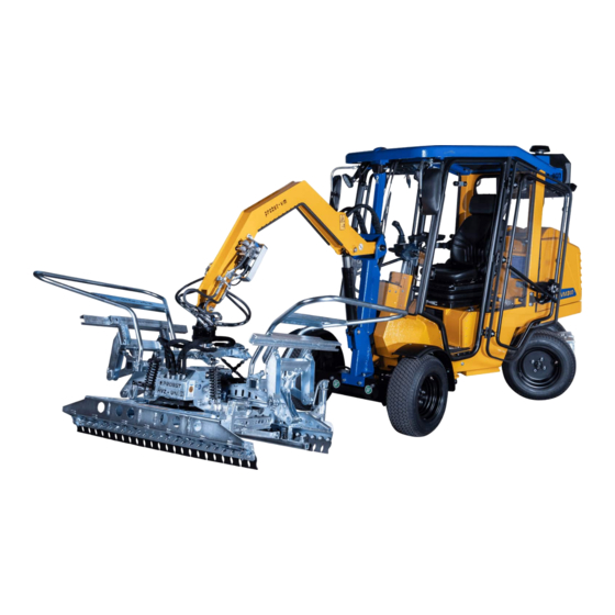
General 13 / 36 Survey and construction VM-301-PAVERMAX VM-301-K-PAVERMAX 5150.0022+5150.0023 (41500820) -
Page 16: Technical Data
0°C:SAE10W, 0°-25°C:SAE20, over 25°C:SAE30 Hydraulic oil 18 l HLP 46 Kubota Diesel motor D 1105 Technical data see: Kubota Diesel motor D 1105 Seat: Height adjustable, , adjustable backrest, adjustable spring power At adequate driving speed and lowered load. VM-301-PAVERMAX VM-301-K-PAVERMAX 5150.0022+5150.0023 (41500820) -
Page 17: Description And Operation
Description and Operation 15 / 36 4 Description and Operation In conditional of the outdoor temperature it is absolute outdoor temperature over outdoor temperature necessary to keep the warm up times at every daily use 10°C(50 F): under 10°C(14 F): (before the first motion of travelling) of the installation 5 minutes 10 minutes... -
Page 18: Hydraulic-Oil Level
Description and Operation 16 / 36 4.1.3 Hydraulic-oil level ● The installation machine VM-301-PAVERMAX has to stand of even and levelled ground to check the hydraulic oil. ● The lifting arm has to be completely lowered down. ● The oil level must be in the middle of the inspection windows (6). -
Page 19: Main Switch
Description and Operation 17 / 36 4.1.5 Main switch ● Before starting the VM-301-PAVERMAX put in the main switch (8) ● The main switch is below the engine cover on the right hand side. 4.1.6 Accelerator Lever of the accelerator (9) has to stay in position by the friction of the spring washers To adjust the leaver of the accelerator the stop nut on the inside of the leaver has to be tightened by a key size... -
Page 20: Control Displays
Description and Operation 18 / 36 4.1.7 Control displays Oil pressure control The oil control light (12) has to be illuminated when the ignition (13) is on step 1. The light must not be illuminated when the motor is running. Battery control The battery control light (14) has to be illuminated when the ignition (13) is on step 1. -
Page 21: Starting The Engine
Description and Operation 19 / 36 Starting the engine Insert and activate main switch (8) before starting (always take this main switch with you after end of work security of the VM against theft!) Before starting the engine daily checks have to be carried out. ... - Page 22 Description and Operation 20 / 36 Adjust the driver’s seat according to the driver’s height and (25) (26) weight. Lever (right hand, below) forward and backward. Treble height adjustment: pull the complete seat upwards. Lever for adjust backrest back and forth (rear, left hand). Turn at twist handle to the right or left to adjust the weight of the driver (twist handle is at the front in the middle, below).
-
Page 23: Fixing Of Attachments
Description and Operation 21 / 36 ● Drive with load (stone slab) carefully to the place of destination. ● Lower the load (with the left foot pedal Fig. B). ● Place the load on the floor and move the joystick fprward (vacuum is interrupted). - Page 24 Description and Operation 22 / 36 (30) 5150.0022+5150.0023 (41500820)
-
Page 25: Bypass-Valve (Towing The Vm-301-Pavermax )
Description and Operation 23 / 36 Bypass-valve (towing the VM-301-PAVERMAX ) ● It is possible to move the laying machine VM-301-PAVERMAX without engine power (e.g. engine damage). Only open the bypass-vale (at the hydrostat under the driver´s seat). ● Open the engine cover - by pulling the handle (Fig. A) and tip the engine cover backwards (Fig. B). ●... -
Page 26: Long-Term Storage Of Vm-301-Pavermax
Description and Operation 24 / 36 Fig. E Fig. F Long-term storage of VM-301-PAVERMAX If the installation machine must be stored during a longer period: ● store the installation machine at an even and try place in a hall or, ●... -
Page 27: Maintenance And Care
Maintenance and care 25 / 36 5 Maintenance and care Maintenance To ensure the correct function, safety and service life of the device the following points must be executed in the maintenance interval. Used only original spare parts, otherwise the warranty expires. All operations may only be made in closed state of the device! For all operations you have to make sure, that the device will not close unintended. -
Page 28: Hydraulic
Maintenance and care 26 / 36 Retighten all 5 mounting nuts (M7) at the exhaust silencer 18-20 Nm. After 50 operating hours Kubota D1105 - Sequence for tightening torque: see marking HYDRAULIC Service interval Maintenance work First inspection after ●... - Page 29 Maintenance and care 27 / 36 Regular Inspections (refer to enclosed KUBOTA operating manual) To maintain efficient engine functions and to ensure long engine service life, inspections are required at scheduled intervals in accordance with the following table. First 50 h Every 200 h Every 1000 h Every year...
-
Page 30: Recharching Of The Battery
Maintenance and care 28 / 36 To disconnect the electric system from the battery, the main switch must be activated at the VM-301-PAVERMAX at the right hand side and at the VM 204 at the left hand side of the engine under the hood. At about the same place, there is a lock to be pulled out to unlock the cover, where the seat is fixed to. -
Page 31: Lubrication Chart
Maintenance and care 29 / 36 Lubrication Chart 5150.0022+5150.0023 (41500820) - Page 32 Maintenance and care 30 / 36 5150.0022+5150.0023 (41500820)
- Page 33 Maintenance and care 31 / 36 5150.0022+5150.0023 (41500820)
-
Page 34: Trouble Shooting
Maintenance and care 32 / 36 Trouble shooting Problem Possible reason Repair Engine does not work Refer to operation manual for Kubota engine Engine is running, but VM does not ● Seat switch is active Press one time the reset button (horn button) Acelerater leaver is loose ●... -
Page 35: Repairs
Maintenance and care 33 / 36 Repairs ● Only persons with the appropriate knowledge and ability are allowed to repair the device. ● Before the device is used again, it has to be checked by an expert. Safety procedures It is the contractors responsibility to ensure that the device is checked by an expert in periods of max. -
Page 36: Hints To The Identification Plate
Example: Hints to the renting/leasing of PROBST devices With every renting/leasing of PROBST devices the original operating instructions must be included unconditionally (in deviation of the users country's language, the respective translations of the original operating instructions must be delivered additionally)! - Page 37 1217 1195 Tragfähigkeit: 500 [kg] Carrying Capacity: 500 [kg] / (1100 lbs.) Installation Machine VM301 PAVERMAX Bei Änderungen Rücksprache TB ! Gewicht: 912,4 kg Schutzvermerk nach DIN 34 beachten! Nachdruck nur mit unserer Genehmigung! Benennung Datum Name Verlegemaschine VM301 Erst. 17.1.2014 M.Kaltenbach PAVERMAX...
- Page 38 41500715 siehe separate Liste see separate list 41500707 24210008 41500711 41500708 siehe separate Liste see separate list 41500718 41500713 20000010 siehe separate Liste see separate list 20450005 26810006 20440004 26810002 33170126 20030008 26990060 24220015 26990061 24220014 26990062 41500723 41500719 41500729 41500704 20040004 33700963...
- Page 39 20440004 33700906 20090055 21590053 21070095 21590072 20490009 20040007 20490008 21590053 Bei Änderungen Rücksprache TB ! 26820024 Gewicht: 8,1 kg Schutzvermerk nach DIN 34 beachten! Nachdruck nur mit unserer Genehmigung! Benennung Datum Name Fensterscheibe hinten links, Erst. 5.2.2014 lukas.zannini vormontiert, für VM301 Gepr.
- Page 40 41500709 41500769 20000003 20100014 26990059 20450004 20000011 20400002 26820023 36600022 20100015 20440004 20450004 20100014 33502778 36600024 36600024 21650030 26990067 21650031 20450005 20100091 20040006 20490008 26820023 21650016 33310001 20040035 © all rights reserved conform to ISO 16016 Datum Name Benennung Türscheibenrahmen, LINKS, Erst.
- Page 41 41500767 26820019 20100015 33701031 20440004 21070095 20490009 20490008 20040007 Bei Änderungen Rücksprache TB ! Gewicht: 18,1 kg Schutzvermerk nach DIN 34 beachten! Nachdruck nur mit unserer Genehmigung! Benennung Datum Name Frontscheibe, vormontiert, für VM301 Erst. 17.2.2014 lukas.zannini Gepr. ( mit Halter, Montagematerial und Dichtungen) Blatt Artikelnummer/Zeichnungsnummer E41500713...
- Page 42 41500768 26820022 21650030 21650031 20040006 26990067 41500710 36600024 20100091 20450005 33502778 20490009 20040035 20440004 36600022 20440003 33310001 20100015 20000004 41500768 21650016 20440003 21070095 20000003 20450004 20400001 26990059 20000130 20400002 36600022 20000012 © all rights reserved conform to ISO 16016 Datum Name Benennung Türscheibenrahmen, RECHTS,...
- Page 43 21590053 21590072 20490009 20040007 20490008 26820024 21070095 20440004 33700906 20090055 21590053 21590053 Bei Änderungen Rücksprache TB ! Gewicht: 8,1 kg Schutzvermerk nach DIN 34 beachten! Nachdruck nur mit unserer Genehmigung! Benennung Datum Name Fensterscheibe hinten rechts, Erst. 6.2.2014 lukas.zannini vormontiert, für VM301 Gepr.
- Page 44 VM-301 /VM-203 Ersatzteile/Spare Parts Reparatursatz/Repair Set Kreuzhebelventil/Joystick valve (41600008) Rev.003 24100007 Kabelbinder / Cable fixer 21590011 Manschette Manschette (rubber cuff) 20040030 Senkkopfschraube (4x) countersunk head screw (4x) 22090021 Grundplatte / Base plate 21550132 O-Ring (2x) O-Ring seal (2x) 00000000 Blindstopfen / Dummy plug 20020066 Zylinderkopfschraube (3x) Cylinder head screw (3x)
- Page 45 Ersatzteile / Spare Parts VM-301/VM-30-K Filterübersicht / Filter overview Filterübersicht / Filter overview VM-301 Hersteller & Bezeichnung Art.-Nr. Motor/Engine (D1105) Manufacturer&Designation Motorölfilter Engine oil filter 26900019 Digöma - D105-BB-EC-1 Kraftstofffilter(Vorfilter) 26900022 Digöma - KL 63 (LH1) Fuel filter (prefilter) Kraftstoff-Filter-Einsatz 26900018 Digöma - DGM/K03185 Fuedl filter cartridge...
- Page 46 Ersatzteile/Spare parts: Filter VM-301 PAVERMAX 51500020 / 51500023...
- Page 47 Ersatzteile/Spare parts: Filter VM-301 PAVERMAX 51500020 / 51500023...
- Page 48 Ersatzteile / Spare Parts VM-301-PAVERMAX VM-301-PAVERMAX (5150.0020 / 5150.0022) VM-301-k-PAVERMAX (5150.0021 / 5150.0023) Seite 1 von 18...
- Page 49 Ersatzteile / Spare Parts VM-301-PAVERMAX 41500001 33140006 22140071 33750063 33140004 33140005 33140006 22430002 30300079 30310041 22000105 22000066 22140071 Seite 2 von 18...
- Page 50 Ersatzteile / Spare Parts VM-301-PAVERMAX 30310041 30300079 41500385 22140071 22210023 22000105 22000105 41500717 41500386 41500286 Seite 3 von 18...
- Page 51 Ersatzteile / Spare Parts VM-301-PAVERMAX 22140071 22000068 20100018 22140041 22140071 22000067 22000067 29040112 22000105 20000084 Seite 4 von 18...
- Page 52 Ersatzteile / Spare Parts VM-301-PAVERMAX 41500062 41500033 26990004 24200003 26990003 24130003 29030008 24390002 24110018 22210023 22140207 22000066 41500048 22050005 20090003 30310042 20000034 20450008 20080003 21850004 21850016 Rad kompl. tire compl. Seite 5 von 18...
- Page 53 Ersatzteile / Spare Parts VM-301-PAVERMAX aktuelles Bild fehlt noch siehe hier Bsp. Bild von VM-203 41600008 22090001 21610006 20100047 20040015 22090007 22090004 26020001 Seite 6 von 18...
- Page 54 Ersatzteile / Spare Parts VM-301-PAVERMAX 21600003 20540010 26900007 26900011 22000103 Ölfilter- Einsatz Oil filter cartridge 27150003 26200002 26920009 10700035 41500035 23210002 41500015 26190003 41500055 26990002 Seite 7 von 18...
- Page 55 Ersatzteile / Spare Parts VM-301-PAVERMAX 00000000 20020050 22050010 41500178 21030001 20540010 21990003 26990003 41500108 41500109 21000075 41500110 Seite 8 von 18...
- Page 56 Ersatzteile / Spare Parts VM-301-PAVERMAX 21650001 2008000 20190002 21070001 41500046 26990005 Seite 9 von 18...
- Page 57 Ersatzteile / Spare Parts VM-301-PAVERMAX 25050001 41500097 25000006 26110009 26900020 Luftfilter Air filter 26110007 21050052 27140001 21990003 41500098 41500104 26900022 21700016 21050058 26120002 33160004 26900017 26090002 26090018 Seite 10 von 18...
- Page 58 Ersatzteile / Spare Parts VM-301-PAVERMAX 41500717 41500116 41500028 25050003 41500053 25050003 10700035 33750063 20900004 20400053 20020056 41500120 41500122 21600005 20020018 20450008 21610002 21610002 41500083 22230001 Seite 11 von 18...
- Page 59 Ersatzteile / Spare Parts VM-301-PAVERMAX 22160049 22400001 21610002 22140050 22160056 22070002 22140050 22160002 33140001 33140012 22000002 Seite 12 von 18...
- Page 60 Ersatzteile / Spare Parts VM-301-PAVERMAX 41500121 21610005 20000050 33140009 20450005 22030008 20100015 22140068 22070001 22140050 33140016 27080001 22000046 21050058 33140010 22000223 20000033 21610005 22000044 33140006 33140005 20000016 20450006 26130001 21070001 33160004 21600006 24100010 22140111 22000044 24100226 33140016 25200005 22600007 Seite 13 von 18...
- Page 61 Ersatzteile / Spare Parts VM-301-PAVERMAX 24110002 24110009 26900007 22100006 Seite 14 von 18...
- Page 62 Ersatzteile / Spare Parts VM-301-PAVERMAX 33750063 22030008 22160050 21610005 22000046 22160004 22000046 33140009 41500057 41500121 33140002 21610005 22000045 22070001 22140050 22000223 33140016 22160010 22000045 22100005 Seite 15 von 18...
- Page 63 Ersatzteile / Spare Parts VM-301-PAVERMAX 41500211 41500209 24200001 41500019 00000000 21990002 Seite 16 von 18...
- Page 64 Ersatzteile / Spare Parts VM-301-PAVERMAX 22160002 22140085 22000283 22000284 33140002 22120006 22140058 22120007 33170010 221200010 22140067 22120006 22080018 22140058 22160110 33140002 22140073 22120001 22160002 22120011 22120011 22120001 33170009 22000284 33170010 22000283 Seite 17 von 18...
- Page 65 Ersatzteile / Spare Parts VM-301-PAVERMAX 22000283 22160002 22000284 33170010 22140058 22160002 22080018 33140002 33170009 22120007 33170009 22140058 22080018 22120006 22140067 22160110 22000284 22000283 Seite 18 von 18...
- Page 66 VM-301 /VM-203 Ersatzteile/Spare Parts Reparatursatz/Repair Set Kreuzhebelventil/Joystick valve (41600008) Rev.003 24100007 Kabelbinder / Cable fixer 21590011 Manschette Manschette (rubber cuff) 20040030 Senkkopfschraube (4x) countersunk head screw (4x) 22090021 Grundplatte / Base plate 21550132 O-Ring (2x) O-Ring seal (2x) 00000000 Blindstopfen / Dummy plug 20020066 Zylinderkopfschraube (3x) Cylinder head screw (3x)
- Page 67 A51500020-23 VM-301 Beklebt von probst 29040243 (DE/GB) 29040314 (DE/FR) 29040623 (wenn zutreffend) 29040441 29040056 29040681 (wenn zutreffend) P 21.06.2018_V3 1 / 6 Einige der Abbildungen sind möglicherweise optionales Zubehör des Gerätes/Some of pictures may be optional equipment of the device.
- Page 68 A51500020-23 VM-301 Beklebt von probst 29040613 (DE) 29040614 (GB) 29040615 (FR) 29040610 (DE) 29040611 (GB) 29040612 (FR) P 21.06.2018_V3 2 / 6 Einige der Abbildungen sind möglicherweise optionales Zubehör des Gerätes/Some of pictures may be optional equipment of the device.
- Page 69 A51500020-23 VM-301 Beklebt von probst 29040716 29040755 P 21.06.2018_V3 3 / 6 Einige der Abbildungen sind möglicherweise optionales Zubehör des Gerätes/Some of pictures may be optional equipment of the device.
- Page 70 A51500020-23 VM-301 Aufkleber zu A41500833 VM-301 (VOP) Beklebt von VOP 29040259 29040253 29040756 29040451 29040396 29040483 Auf beiden Seiten/on both sides 29040762 Auf beiden Seiten/ on both sides 29040687 P 21.06.2018_V3 4 / 6 Einige der Abbildungen sind möglicherweise optionales Zubehör des Gerätes/Some of pictures may be optional equipment of the device.
- Page 71 A51500020-23 VM-301 Aufkleber zu A41500833 VM-301 (VOP) Beklebt von VOP 29040551 29040485 29040260 29040450 29040267 P 21.06.2018_V3 5 / 6 Einige der Abbildungen sind möglicherweise optionales Zubehör des Gerätes/Some of pictures may be optional equipment of the device.
- Page 72 A51500020-23 VM-301 Aufkleber zu A41500833 VM-301 (VOP) Beklebt von VOP 29040759 29040760 29040616 29040666 29040220 P 21.06.2018_V3 6 / 6 Einige der Abbildungen sind möglicherweise optionales Zubehör des Gerätes/Some of pictures may be optional equipment of the device.
- Page 73 After each completed performance of a maintenance interval the included form must be fill out, stamped, signed and send back to us immediately 1) via e-mail to service@probst-handling.de / via fax or post Operator: _ _ _ _ _ _ _ _ _ _ _ _ _ _ _ _ _...
Need help?
Do you have a question about the VM-301-K-PAVERMAX and is the answer not in the manual?
Questions and answers