
Related Manuals for Gree GMV5E Series


Summary of Contents for Gree GMV5E Series
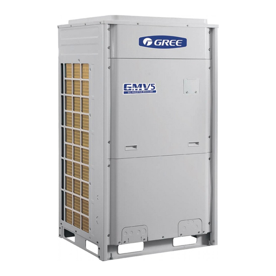
- Page 1 GMV5E DC INVERTER VRF UNITS (GC201806-III) Capacity: 22.4kW~246.0kW Rated Frequency: 50Hz & 60Hz Operation Range: Cooling: -5~52° C Heating: -20~24° C...
-
Page 2: Table Of Contents
Contents Preface ........................1 Chapter 1 Introduction to Basic Features of Units ..........1 1.1 Basic Operating Principle ....................1 1.2 Model list ......................... 2 1.3 Internal Piping Design of the Units .................. 3 1.4 Basic Parameters of Unit ....................7 1.5 Electrical Parameters .................... - Page 3 5.5 Fitting pipe between Outdoor Unit and the First Manifold ..........43 6 Pipe Installation and Insulation ................49 6.1 Pipe Installation for the Cooling System ............... 49 6.2 Pipe Installation for the Condensate Water System ............58 6.3 Insulation System ......................62 7 Electric and Controller Installation ..............
- Page 4 3.4 Assembling and Disassembling Key Parts of ODUs ........... 269 3.5 Exploded Views and Spaer Part List ................282 4 Common Parameter Lists ................. 294 4.1 R410a refrigerant pressure / saturation temperature list ..........294 4.2 Resistance / temperature lists of temperature sensors ..........295 4.3 Voltage / pressure lists of pressure sensors ...............
-
Page 5: Preface
GMV5E DC INVERTER VRF UNITS SERVICE MANUAL Preface This manual specifies safe operation requirements for GMV5E series VRF units from perspectives of engineering and installation, commissioning and maintenance, as well as basic principles and implementation methods. Professional operators must abide by relevant national (local) safety requirements and technical specifications set forth in this manual during operations;... -
Page 6: Model List
GREE GMV5E DC INVERTER VRF UNITS SERVICE MANUAL 1.2 Model list Nominal Model Power Supply Capacity Appearance Model name Refrigerant Product Code Ph, V, Hz 3, 380-415, GMV-224WM/E-X R410A CN851W1790 22.4 50/60 3, 380-415, GMV-280WM/E-X R410A CN851W1800 28.0 50/60 3 ,380-415,... -
Page 7: Internal Piping Design Of The Units
GREE GMV5E DC INVERTER VRF UNITS SERVICE MANUAL 1.3 Internal Piping Design of the Units 1.3.1 Piping Diagram of GMV-224WM/E-X, GMV-280WM/E-X, GMV-280WM/E1-X and GMV-335WM/E-X... - Page 8 GREE GMV5E DC INVERTER VRF UNITS SERVICE MANUAL 1.3.2 Piping Diagram of GMV-400WM/E-X and GMV-450WM/E1-X...
- Page 9 GREE GMV5E DC INVERTER VRF UNITS SERVICE MANUAL 1.3.3 Piping Diagram of GMV-450WM/E-X, GMV-504WM/E-X, GMV-560WM/E-X and GMV-615WM/E-X 1.3.4 Names and Main Functions of Components Name Main Function Adjusts its own rotational speed based on the actual requirement of the system to Compressor implement capacity control.
- Page 10 GREE GMV5E DC INVERTER VRF UNITS SERVICE MANUAL Name Main Function Heat exchanger Used for outdoor heat exchange. Strengthens heat exchanging. Defrosting temperature Used for defrosting detection. sensor Electronic expansion Controls refrigerant adjustment in heating mode. valve for heating One-way valve Controls refrigerant flow direction.
-
Page 11: Basic Parameters Of Unit
GREE GMV5E DC INVERTER VRF UNITS SERVICE MANUAL 1.4 Basic Parameters of Unit GMV-224WM/E- GMV-280WM/E- GMV-280WM/E1 GMV-335WM/E- GMV-400WM/E- Model Product Code CN851W1790 CN851W1800 CN851W2200 CN851W1810 CN851W1820 Refrigeration Capacity Power Supply 380-415V 3N~ 50Hz/60Hz Cooling Nom. 22.4 33.5 Rated 31.5 31.5 37.5... - Page 12 GREE GMV5E DC INVERTER VRF UNITS SERVICE MANUAL GMV-680WM/E- GMV-730WM/E- GMV-785WM/E- GMV-850WM/E- GMV-900WM/E- Model Refrigeration Capacity GMV-280WM/E- GMV-280WM/E- GMV-280WM/E- GMV-280WM/E- GMV-280WM/E- — Combination Mode GMV-400WM/E- GMV-450WM/E- GMV-504WM/E- GMV-560WM/E- GMV-615WM/E- Power Supply 380-415V 3N~ 50Hz/60Hz Cooling Nom. 78.4 89.5 Rated 76.5 81.5...
- Page 13 GREE GMV5E DC INVERTER VRF UNITS SERVICE MANUAL GMV-1235WM GMV-1300WM GMV-1350WM GMV-1410WM GMV-1460WM Model /E-X /E-X /E-X /E-X /E-X Refrigeration Capacity GMV-280WM/ GMV-280WM/ GMV-335WM/ GMV-280WM/ GMV-615WM/ E-X + E-X + E-X + E-X + E-X + GMV-450WM/ GMV-450WM/ GMV-450WM/ GMV-560WM/ —...
- Page 14 GREE GMV5E DC INVERTER VRF UNITS SERVICE MANUAL GMV-1800W GMV-1845WM GMV-1908WM GMV-1962WM GMV-2016WM Model M/E-X /E-X /E-X /E-X /E-X Refrigeration Capacity GMV-280WM/E- GMV-280WM/E- GMV-280WM/E- GMV-560WM/ GMV-615WM/ E-X + E-X+ GMV-450WM/E- GMV-504WM/E- GMV-560WM/E- GMV-615WM/ GMV-615WM/ — Combination Mode E-X + E-X+...
-
Page 15: Electrical Parameters
GREE GMV5E DC INVERTER VRF UNITS SERVICE MANUAL GMV-2295WM/E- GMV-2350WM/E- GMV-2405WM/E- GMV-2460WM/E- Model Refrigeration Capacity GMV-450WM/E-X GMV-504WM/E-X GMV-560WM/E-X GMV-615WM/E-X +GMV-615WM/E-X +GMV-615WM/E-X +GMV-615WM/E-X +GMV-615WM/E-X — Combination Mode +GMV-615WM/E-X +GMV-615WM/E-X +GMV-615WM/E-X +GMV-615WM/E-X +GMV-615WM/E-X + GMV-615WM/E-X +GMV-615WM/E-X +GMV-615WM/E-X Power Supply 380-415V 3N~ 50Hz/60Hz Cooling Nom. - Page 16 GREE GMV5E DC INVERTER VRF UNITS SERVICE MANUAL Circuit Circuit breaker Wire size of breaker capacity for Wire size of combined unit Model Basic models power supply capacity combined units GMV-900WM/E-X 280+615 25+63 2.5+10 2.5×5+10×5 GMV-960WM/B-X 335+615 32+63 4.0+10 4.0×5+10×5...
- Page 17 GREE GMV5E DC INVERTER VRF UNITS SERVICE MANUAL area must be expanded to prevent overload current from burning the wire or causing fire hazard. ⑦ Specification of circuit breaker is based on the working condition where the ambient temperature of circuit breaker is 40° C. If working condition is different, please adjust the specification according to national standard.
- Page 18 GREE GMV5E DC INVERTER VRF UNITS SERVICE MANUAL Circuit diagram of GMV-335WM/E-X Circuit diagram of GMV-400WM/E-X and GMV-450WM/E1-X...
-
Page 19: Optional Accessories
This drawing is just for reference; please always refer to the electric wiring stuck to the unit for actual wiring. 1.6 Optional Accessories GMV5E series VRF units support the following optional accessories: Model Remarks For the model selection method, see the part of... -
Page 20: Basic Requirement For Pipe Connection
GREE GMV5E DC INVERTER VRF UNITS SERVICE MANUAL Model Remarks Applicable to the unit of CAN bus communication Debugging software DE40-33/A(C) technology Applicable to the unit of CAN bus communication Remote Software FE30-24/DF(B) technology monitoring MODbus system ME30-24/DF(B) gateway Note: Contact local sales company for optional accessories. - Page 21 GREE GMV5E DC INVERTER VRF UNITS SERVICE MANUAL GMV-450WM/E-X, GMV-504WM/E-X, GMV-560WM/E-X and GMV-615WM/E-X Note: ① Functions of oil check valve: During after-sale maintenance, the oil check valve can be used to extract lubricating oil samples, which are further detected to analyze the oil quality in the system.
- Page 22 GREE GMV5E DC INVERTER VRF UNITS SERVICE MANUAL Capacity Range of Connected IDU (kW) ODU model Max number of connectable IDU (unit) Minimum Capacity Maximum Capacity GMV-450WM/E-X 22.5 60.8 GMV-504WM/E-X 25.2 68.0 GMV-560WM/E-X 28.0 75.6 GMV-615WM/E-X 30.8 83.0 GMV-680WM/E-X 34.0 91.8...
-
Page 23: Precautions On Refrigerant Leakage
(2) GMV5E series VRF units adopt the R410A refrigerant, which is nonflammable and nontoxic. However, the space for refrigerant leakage must be sufficient to ensure that the refrigerant concentration does not exceed that specified in the safety requirement;... -
Page 24: Chapter 2 Installation
GREE GMV5E DC INVERTER VRF UNITS SERVICE MANUAL Chapter 2 Installation 1 Engineering Installation Preparation 1.1 Installation Safety Personnel and property safety are highly concerned during the entire installation process. Installation implementation must abide by relevant national safety regulations to ensure personnel and property safety. - Page 25 GREE GMV5E DC INVERTER VRF UNITS SERVICE MANUAL Installation Problem Possible Consequence The ratio of slop for condensate water pipe is Reverse slop or inconsistent connection of condensate water pipe can hinder the insufficient or the condensate smooth drainage and cause leakage of the IDU.
-
Page 26: Cooperation Between Different Professions
GREE GMV5E DC INVERTER VRF UNITS SERVICE MANUAL 1.3 Cooperation Between Different Professions A quality installation of air conditioning engineering depends on careful organization and close cooperation between different professions such as architecture, structure, electric, water supply and drainage, fire-fighting, and decoration. Pipes must be laid in places away from any automatic spray head for fire-fighting, and must be reasonably arranged to ensure that the pipes fit the electric, luminaries, and decoration. - Page 27 GREE GMV5E DC INVERTER VRF UNITS SERVICE MANUAL Any nonconformity must be resolved through coordination.
-
Page 28: Onsite Review Of Design Drawing
GREE GMV5E DC INVERTER VRF UNITS SERVICE MANUAL 1.4 Onsite Review of Design Drawing Installation personnel must carefully read and understand the design scheme and drawings provided by engineering designers, and prepare detailed and feasible construction organization design after reviewing the onsite status. -
Page 29: Construction Organization Process
GREE GMV5E DC INVERTER VRF UNITS SERVICE MANUAL 1.5 Construction Organization Process 2 Material Selection 2.1 Requirement for Selecting Construction Materials The materials, equipment and instruments used during air conditioning engineering construction must have certifications and test reports. Products with fireproof requirements must be provided with fireproof inspection certificates and must meet national and relevant compulsory standards. -
Page 30: Requirement For Selecting Major Materials
GREE GMV5E DC INVERTER VRF UNITS SERVICE MANUAL 2.2 Requirement for Selecting Major Materials 2.2.1 Copper pipe a. Material requirement: Dephosphorization drawing copper pipe for air conditioners b. Appearance requirement: The inner and outer surface of pipe should be smooth without pinhole, crack, peeling, blister, inclusion, copper powder, carbon deposition, rust, dirt or severe oxide film, and without obvious scratch, pit, spot and other defects. -
Page 31: Installation Space Requirement
GREE GMV5E DC INVERTER VRF UNITS SERVICE MANUAL mm, the thickness of insulation material should be at least 15 mm. 2.2.4 Communication cable and control cable Note: For air conditioning units installed in places with strong electromagnetic interference, shielded wire must be used as the communication cables of the IDU and wired controller, and shielded twisted pairs must be used as the communication cables between IDUs and between the IDU and ODU. -
Page 32: Odu Dimensions And Installation Hole Size
GREE GMV5E DC INVERTER VRF UNITS SERVICE MANUAL 3.2 ODU Dimensions and Installation Hole Size Outline and Physical Dimention of GMV-224WM/E-X, GMV-280WM/E1-X and GMV-280WM/E-X unit. unit:mm Outline and Physical Dimention of GMV-335WM/E-X, GMV-400WM/E-X and GMV-450WM/E1-X unit. unit:mm... -
Page 33: Installation Space Requirement For Odu
GREE GMV5E DC INVERTER VRF UNITS SERVICE MANUAL Outline and Physical Dimention of GMV-450WM/E-X, GMV-504WM/E-X, GMV-560WM/E-X and GMV-615WM/E-X unit. unit:mm 3.3 Installation Space Requirement for ODU (1) If all sides of the ODU (including the top) are surrounded by walls, process according to the... - Page 34 GREE GMV5E DC INVERTER VRF UNITS SERVICE MANUAL Installation space requirements for triple-module unit unit:mm Installation space requirement for quad-module unit unit:mm...
- Page 35 GREE GMV5E DC INVERTER VRF UNITS SERVICE MANUAL (2) In principle, if a crown wall (obstacles for keeping out the wind) exists over the machine, a distance of at least 3000 mm should be left between the top of the machine and the crown wall. If the front, rear, left and right sides of the machine are open spaces, the distance between the top of the machine and the crown wall should be at least 1500 mm, as shown in Fig.
- Page 36 GREE GMV5E DC INVERTER VRF UNITS SERVICE MANUAL (3) Monsoons must be considered during ODU installation. Anti-monsoon installation requirements for unit not connecting exhaust duct: Anti-monsoon installation requirements for unit connecting exhaust duct: (4) Snow must be considered during ODU installation.
- Page 37 GREE GMV5E DC INVERTER VRF UNITS SERVICE MANUAL the aperture opening rate of shutters must be at least 80%, and the angle between the shutters and the horizontal plane should be less than 20° . Requirements for installing exhaust air duct are as follows: i.
- Page 38 GREE GMV5E DC INVERTER VRF UNITS SERVICE MANUAL d) Use the tin foil to seal the joints and check the joints' reliability. Step 1 Step 2 Step 3 Step 4 Step 5 Step 6 Method 2: a) Install the ODU (2) and steel-plate ventilating duct (1). Take out the grille from the top of the top case component.
- Page 39 GREE GMV5E DC INVERTER VRF UNITS SERVICE MANUAL hand-operated electric drill to drill holes and fasten the canvas casing onto the unit through steel bar by using tapping screws. c) Pull up the canvas casing reversely and use the steel bar to press the canvas casing tightly onto the counter flange of the steel-plate ventilating duct.
-
Page 40: Requirements On Foundation Installation
GREE GMV5E DC INVERTER VRF UNITS SERVICE MANUAL 4 Requirements on Foundation Installation 4.1 ODU Foundation The concrete foundation of the ODU must be strong enough. Ensure that the drainage is smooth and that the ground drainage or floor drainage is not affected. -
Page 41: Vibration Reduction For Odu
GREE GMV5E DC INVERTER VRF UNITS SERVICE MANUAL 4.3 Vibration Reduction for ODU The ODU must be fixed securely. Apply a thick rubber sheet or corrugated damping rubber pad with thickness of 20 mm or more and width of 100 mm or more between the ODU and the foundation, as shown in the following figures. -
Page 42: Piping Connection
GREE GMV5E DC INVERTER VRF UNITS SERVICE MANUAL Installation personnel should use tube bender when bending the pipe. 6) Don't forbibly stretch the pipe joint, otherwise indoor capillary or other pipes might be damaged and lead to refrigerant leakage. 5 Piping Connection 5.1 Schematic Diagram of Piping Connection... -
Page 43: Allowable Pipe Length And Drop Height Among Indoor And Outdoor Units
GREE GMV5E DC INVERTER VRF UNITS SERVICE MANUAL GMV-335WM/E-X, GMV-400WM/E-X and GMV-450WM/E1-X GMV-450WM/E-X, GMV-504WM/E-X, GMV-560WM/E-X and GMV-615WM/E-X 5.3 Allowable pipe length and drop height among indoor and outdoor units Y type branch joint is adopted to connected indoor and outdoor units. Connecting method is shown in the figure below Remark Equivalent length of one Y-type manifold is about 0.5m. - Page 44 GREE GMV5E DC INVERTER VRF UNITS SERVICE MANUAL L10: Length from the first branch to the farthest IDU; L11: Length from the first branch to the nearest IDU; Equivalent length of branch of IDU is 0.5m. Allowable R410A Refrigerant System...
-
Page 45: Connection Pipe Among Outdoor Modules
GREE GMV5E DC INVERTER VRF UNITS SERVICE MANUAL Outdoor Model Gas pipe size(mm) Liquid pipe size(mm) Φ41.3 Φ22.2 GMV-1180WM/E-X Φ41.3 Φ22.2 GMV-1235WM/E-X Φ41.3 Φ22.2 GMV-1300WM/E-X Φ41.3 Φ22.2 GMV-1350WM/E-X Φ44.5 Φ22.2 GMV-1410WM/E-X Φ44.5 Φ22.2 GMV-1460WM/E-X Φ44.5 Φ22.2 GMV-1515WM/E-X Φ44.5 Φ22.2 GMV-1580WM/E-X Φ44.5... - Page 46 GREE GMV5E DC INVERTER VRF UNITS SERVICE MANUAL Note: When the distance between outdoor units exceeds 2m, U-type oil trap should be added at low-pressure gas pipe. A+B≤10m. Pipe connection among ODUs must meet the following requirements: Module pipe interface...
-
Page 47: Fitting Pipe Between Outdoor Unit And The First Manifold
GREE GMV5E DC INVERTER VRF UNITS SERVICE MANUAL 5.5 Fitting pipe between Outdoor Unit and the First Manifold (1) For single module system, pipe size (between outdoor unit and the first manifold) is determined by that of outdoor unit. Pipe size of basic outdoor module is shown as follows:... - Page 48 GREE GMV5E DC INVERTER VRF UNITS SERVICE MANUAL Pipe between module and branch of ODU Basic Module Gas Pipe(mm) Liquid Pipe(mm) Φ25.4 Φ12.7 GMV-335WM/E-X Φ25.4 Φ12.7 GMV-400WM/E-X Φ28.6 Φ12.7 GMV-450WM/E1-X Φ28.6 Φ12.7 GMV-450WM/E-X Φ28.6 Φ15.9 GMV-504WM/E-X Φ28.6 Φ15.9 GMV-560WM/E-X Φ28.6 Φ15.9...
- Page 49 GREE GMV5E DC INVERTER VRF UNITS SERVICE MANUAL (4) Fitting pipe between the first manifold from indoor unit and the end manifold from outdoor unit Single module unit Pipe between ODU and the first branch of IDU Basic Module(single module)
- Page 50 GREE GMV5E DC INVERTER VRF UNITS SERVICE MANUAL Pipe between ODU and the first branch of IDU Total rated capacity of outdoor modules (multi-modular system) Gas Pipe(mm) Liquid Pipe(mm) Φ31.8 Φ19.05 GMV-960WM/E-X Φ38.1 Φ19.05 GMV-1010WM/E-X Φ38.1 Φ19.05 GMV-1065WM/E-X Φ38.1 Φ19.05 GMV-1130WM/E-X Φ38.1...
- Page 51 GREE GMV5E DC INVERTER VRF UNITS SERVICE MANUAL Manifold at indoor unit side Manifold at indoor unit side can be selected as per total capacity of downstream indoor unit(s). Refer to the following table. Outdoor unit 1 Outdoor unit 2...
- Page 52 GREE GMV5E DC INVERTER VRF UNITS SERVICE MANUAL (5) Fitting pipe between manifolds Pipe size (between two manifolds at indoor unit side) is based on the total capacity of upstream indoor unit(s). Fitting Pipe Size between Indoor Manifolds Total Rated Capacity X(kW) of Downstream Indoor Units...
-
Page 53: Pipe Installation And Insulation
GREE GMV5E DC INVERTER VRF UNITS SERVICE MANUAL 6 Pipe Installation and Insulation 6.1 Pipe Installation for the Cooling System 6.1.1 Precautions on Pipe Direction Design Refrigerant pipe layout must be designed in accordance with the following principles: (1) The air conditioning installation should not damage the bearing structure or the decorative style. - Page 54 GREE GMV5E DC INVERTER VRF UNITS SERVICE MANUAL 6.1.2 Processing to Refrigerant Pipes 6.1.2.1 Cut-off and Burring Use a special-purpose pipe cutter to cut copper pipes instead of using a hacksaw. Cut the pipes gently to ensure that the copper pipe does not deform.
- Page 55 GREE GMV5E DC INVERTER VRF UNITS SERVICE MANUAL 6.1.2.5 Flaring Another mode of pipe connection is flare opening connection, which requires pipe flaring before connection. Before pipe flaring, apply appropriate amount of lubricant on the surface of the opening to ensure smooth pass of flaring nuts and avoid pipe distortion.
- Page 56 GREE GMV5E DC INVERTER VRF UNITS SERVICE MANUAL Select built-in metal fittings in accordance with local regulations. 6) Installing Expansion Bolts Use expansion bolts when built-in metal fittings are unavailable due to design change. 7) Installing Expansion Bolts If the foot pedal is 2 m or more from the ground, there must be three points of support.
- Page 57 GREE GMV5E DC INVERTER VRF UNITS SERVICE MANUAL A: External Diameter of the Pipe (mm) B: Minimum Insertion Depth (mm) D-A: Gap between Pipes (mm) Φ6.35 0.05-0.21 Φ9.52 Φ12.7 Φ15.8 0.05-0.27 Φ19.05 Φ22.2 Φ25.4 Φ28.6, 0.05-0.30 Φ31.8 Φ38.1 0.15-0.35 Φ44.5 Φ54.1...
- Page 58 GREE GMV5E DC INVERTER VRF UNITS SERVICE MANUAL E3. The length of a straight pipe between two manifolds cannot be less than 500 mm. E4. The length of a straight pipe before the main pipe port of the manifold cannot be less than 500 mm.
- Page 59 GREE GMV5E DC INVERTER VRF UNITS SERVICE MANUAL Branches of a manifold must be laid parallel and cannot be wrapped in superimposed mode. F. T-type manifold can be laid in the following ways: F1. T-type manifold must be installed horizontally with inclination.
- Page 60 GREE GMV5E DC INVERTER VRF UNITS SERVICE MANUAL F4. Suspend the header to the ceiling and be sure to install it so that the outlet pipes are horizontal at the lower side. F5. The downstream of T-type manifold pipe cannot connect with Y-type manifold pipe and T-type manifold pipe Equivalent length of one Y-type manifold pipe is about 0.5m.
- Page 61 Then insert the copper pipe to proper depth. A concave bag for positioning is available to the manifold purchased from Gree. I. Because the manifold structure is complex, perform with care to ensure tight insulation.
-
Page 62: Pipe Installation For The Condensate Water System
GREE GMV5E DC INVERTER VRF UNITS SERVICE MANUAL The distance cannot Ceiling be less than 500 mm. Air pipe indoor unit Manhole Gas pipe Liquid pipe (9) Filter and Drier Installation for the ODU As the piping for the VRF system is complex, it is recommended that a filter is installed for the gas pipe and a drier is installed for the liquid pipe during construction. - Page 63 GREE GMV5E DC INVERTER VRF UNITS SERVICE MANUAL fixed outside the insulation layer. The height of the clamp can be adjusted. (2) Distance between Hangers Φ≤25 32>Φ≥25 Φ≥32 External Diameter of the Pipe (mm) Distance between Horizontal Pipes (mm) 1000...
- Page 64 GREE GMV5E DC INVERTER VRF UNITS SERVICE MANUAL (3) When connecting the drain pipe branches to the main pipe, lead through from the above part of the main pipe. (4) Install the trap Install the trap as shown in following Fig ...
- Page 65 GREE GMV5E DC INVERTER VRF UNITS SERVICE MANUAL 6.2.4.2 Drain Pipe Installation for IDU (1) Use pipe clips instead of applying glue to connect the hoses provided upon delivery and plastic pipes on the device. Connect the other end of the joint to the elbow. The height from the suction inlet of the discharge pump is about 200 to 500 mm.
-
Page 66: Insulation System
GREE GMV5E DC INVERTER VRF UNITS SERVICE MANUAL 6.3 Insulation System 6.3.1 Insulation for the Refrigerant Pipe System 6.3.1.1 Insulation Materials Use closed-cell foam insulation materials with flame retardant grade of B1. The heat conductivity is not greater than 0.035 w/(m· k) when the average temperature is 0° C. -
Page 67: Electric And Controller Installation
GREE GMV5E DC INVERTER VRF UNITS SERVICE MANUAL 6.3.3 Insulation for Air Ducts (1) Insulation for air duct components and devices must be performed after the air leakage test is performed or after quality check. (2) Use centrifugal glass wool or rubber and plastic materials for insulation or use novel insulation air ducts. -
Page 68: Installation Of The Power Cable
GREE GMV5E DC INVERTER VRF UNITS SERVICE MANUAL Elaborate the method with the installation personnel on site no matter which method is adopted. 7.2 Installation of the Power Cable 7.2.1 Precautions 1) The air conditioning unit is category 1 electrical appliance which requires reliable grounding. - Page 69 GREE GMV5E DC INVERTER VRF UNITS SERVICE MANUAL 2) External Connection for Modularly Connected Units The maximum number of connected ODUs (N) and that of connected IDUs (n) are determined based on the combination form of ODUs. For details, see the description on unit capacity configuration.
-
Page 70: Installation Of The Communication System
GREE GMV5E DC INVERTER VRF UNITS SERVICE MANUAL 7.3 Installation of the Communication System The CAN communication network is adopted for GMV5E VRF system. Manual DIP or identification on polarities of the communication power is not required for the IDU. Only the function DIP needs to be set for the ODU. - Page 71 GREE GMV5E DC INVERTER VRF UNITS SERVICE MANUAL 7.3.2 Connection of Communication Cables The communication bus of indoor and ODUs must be connected in series instead of in star mode. The last IDU of the bus shall be connected to a matching resistor (placed in the package of the ODU).
-
Page 72: Vacuumization And Desiccation For The Refrigerant System
GREE GMV5E DC INVERTER VRF UNITS SERVICE MANUAL Communication cable connection for the multi-module system Note: a) If there are multiple modules for the modular ODU, the master unit must be the first ODU module on the communication cable and cannot be connected to the IDU. (The master unit is set by SA8 on the main board of the ODU.) -
Page 73: Vacuumization And Desiccation For The System
GREE GMV5E DC INVERTER VRF UNITS SERVICE MANUAL 8.1.2 Procedure for Performing the Air-tightness Test Stop valves of the gas and liquid pipes of the ODU are turned off at delivery. Before test, apply a small amount of required lubricant on the block nut and pipe terminals and use two wrenches to fix the block nut. -
Page 74: Refrigerant Perfusion
GREE GMV5E DC INVERTER VRF UNITS SERVICE MANUAL The system vacuum pump must be equipped with a check valve. 8.2.2 Procedure and Precautions for Vacuumization and Desiccation 8.2.2.1 Procedure a) Before vacuumization, ensure that the stop valves of the gas and liquid pipes are turned off. - Page 75 GREE GMV5E DC INVERTER VRF UNITS SERVICE MANUAL (1) Method for calculating the quantity of refrigerant perfused for the pipe (A): Quantity of perfused refrigerant for the pipe (A) = ∑ Length of the liquid pipe x Quantity of perfused refrigerant for the liquid pipe per meter Φ28.6...
-
Page 76: Method For Perfusing Refrigerant
GREE GMV5E DC INVERTER VRF UNITS SERVICE MANUAL Modular combination of outdoor unit subjects to combinations that is currently available. 9.2 Method for Perfusing Refrigerant Refrigerant perfusion for the VRF system is classified into pre-perfusion and perfusion during running. 9.2.1 Refrigerant Pre-perfusion... - Page 77 GREE GMV5E DC INVERTER VRF UNITS SERVICE MANUAL Step 8: Perform step 3 again. Step 9: Perform step 5 and step 6 again. Record the weight before perfusion m3 and weight after perfusion m4. Step 10: If there is no sufficient refrigerant and the calculated quantity of refrigerant is not fulfilled for the system, record the current total perfusion quantity.
-
Page 78: Chapter 3 Commissioning Operation
GREE GMV5E DC INVERTER VRF UNITS SERVICE MANUAL Chapter 3 Commissioning Operation 1 Security Requirements 1.1 Precautions for Construction 1. All commissioning and maintenance personnel must learn and strictly comply with construction security specifications. Security measures must be taken especially for outdoor operations. - Page 79 GREE GMV5E DC INVERTER VRF UNITS SERVICE MANUAL DIP Switch Name Meaning Factory Settings Remark systems in the case settings are used without being of centralized control changed. The address DIP switch by multiple systems. is valid only when it is set on the master unit.
- Page 80 GREE GMV5E DC INVERTER VRF UNITS SERVICE MANUAL 2) On the same refrigerating system, the centralized control address DIP switch (SA2_Addr-CC) on a non-master unit is invalid, and it is unnecessary to change the settings. 3) The centralized control address DIP switch (SA2_Addr-CC) on the master unit of a refrigerating system must be set to “0000...
- Page 81 GREE GMV5E DC INVERTER VRF UNITS SERVICE MANUAL Compressor Emergency Operation DIP Switch (SA3_COMP-E) Remark DIP1 DIP2 DIP3 DIP4 DIP5 Shielding the operation of 3# compressor Shielding the operation of 4# compressor Shielding the operation of 5# compressor Shielding the operation of 6# compressor Precautions: A.
- Page 82 GREE GMV5E DC INVERTER VRF UNITS SERVICE MANUAL Precautions: A. When the DIP switch setting is not covered in the above scope, a DIP switch setting exception fault may occur. B. Only one compressor can be set to emergency mode on a module. Subsequent to emergency operation, valves of shielded outdoor unit, including the gas pipe, liquid pipe and oil balance pipe, need to be closed tight by hand.
- Page 83 GREE GMV5E DC INVERTER VRF UNITS SERVICE MANUAL Precautions: A. When the DIP switch setting is not covered in the above scope, a DIP switch setting exception fault may occur. B. Only one fan can be set to emergency mode on a module.
-
Page 84: System Function Button Operations
GREE GMV5E DC INVERTER VRF UNITS SERVICE MANUAL ⑨ DIP Switch Example A. Explanation of DIP switch positions On the DIP switch, “ON” indicates “0” status and the opposite direction indicates "1” status. The position of white lever indicates the position to be set to. - Page 85 GREE GMV5E DC INVERTER VRF UNITS SERVICE MANUAL 2.2.2. Introduction to Functions 2.2.2.1 List of functions Factory Settings Remark Function Function Name Function Meaning Code Code Meaning Fully or partially recovers refrigerants in a Refrigerant faulty module or IDU pipeline according to the It can only ——...
- Page 86 GREE GMV5E DC INVERTER VRF UNITS SERVICE MANUAL Model of Basic Module Maximum Refrigerant Recovery Volume (kg) GMV-400WM/E-X 11.5 GMV-450WM/E1-X 11.5 GMV-450WM/E-X 12.3 GMV-504WM/E-X GMV-560WM/E-X 18.4 GMV-615WM/E-X This function falls into two modes: faulty module refrigerant recovery and IDU pipeline refrigerant recovery.
- Page 87 GREE GMV5E DC INVERTER VRF UNITS SERVICE MANUAL Starting the Silent Mode X Hours Stopping the Nighttime Silent Mode Code after the Daytime Temperature Silent Mode after Continual Noise Degree Reaches the Highest Operations for Y Hours Mode 6 Mode 7...
- Page 88 GREE GMV5E DC INVERTER VRF UNITS SERVICE MANUAL between systems. This function only needs to be set on the master system, which is the system with the centralized control address SA2 DIP switch being “00000”. For details, see the "Centralized Control Address DIP Switch (SA2_Addr-CC)"...
- Page 89 GREE GMV5E DC INVERTER VRF UNITS SERVICE MANUAL LED1 LED2 LED3 Function Code Display Mode Current Progress Display Mode Current Status Display Mode Blinking Blinking Blinking Blinking Then go to step 4 to set corresponding functions. Step 4: Set function parameters.
- Page 90 GREE GMV5E DC INVERTER VRF UNITS SERVICE MANUAL unit). If no button operations are performed on the master unit for five minutes, the function setting automatically quits and the unit restores the current status. The default factory setting is “00”, that is, no silent mode.
- Page 91 GREE GMV5E DC INVERTER VRF UNITS SERVICE MANUAL basic modules are displayed as follows: LED1 LED2 LED3 Function Code Display Mode Refrigerant Recovery Code Display Mode Current Status Display Mode [Module low-pressure Ps] LED3 shows the low-pressure value of a module. If the value is negative, LED3 circularly displays the negative code "nE”...
- Page 92 GREE GMV5E DC INVERTER VRF UNITS SERVICE MANUAL Enter the to-be-confirmed status of system vacuuming mode settings. Step 2: Press "SW7" to confirm entering the to-be-confirmed status of system vacuuming mode settings. All modules are displayed as follows: LED1 LED2...
- Page 93 GREE GMV5E DC INVERTER VRF UNITS SERVICE MANUAL ⑦ n4 Highest capacity output limitation settings Step 1: Confirm entering the n4 highest capacity output limitation settings. The master unit is displayed as follows: LED1 LED2 LED3 Function Code Display Mode...
- Page 94 GREE GMV5E DC INVERTER VRF UNITS SERVICE MANUAL unit. By default, the A7 outdoor silent mode is displayed for query. For example, select the A6 unit cooling/heating function. The display is as follows: LED1 LED2 LED3 Function Code Display Mode ODU Function Mode Code Display Mode ODU Function Mode Code Display Mode Step 5: If the n8 IDU address query is selected, the display is as follows.
- Page 95 GREE GMV5E DC INVERTER VRF UNITS SERVICE MANUAL the historical fault code and module address in an interval of one second in the sequence of fault records. LED2 displays the fault sequence number. If there not historical faults, LED2 and LED3 display “00” by default.
- Page 96 GREE GMV5E DC INVERTER VRF UNITS SERVICE MANUAL Step 8: If the n7 parameter query is selected, the display is as follows. Enter the to-be-confirmed status of parameter query. LED1 LED2 LED3 Function Code Display Mode Current Progress/Mode Display Mode...
- Page 97 GREE GMV5E DC INVERTER VRF UNITS SERVICE MANUAL Parameter Code Parameter Name Unit Remark series. Reserved Module temperature of compressor 1 ° C Module temperature of compressor 2 ° C Module temperature of outdoor fan 1 ° C Module temperature of outdoor fan 2 °...
- Page 98 GREE GMV5E DC INVERTER VRF UNITS SERVICE MANUAL Note: Un indicates the entire-unit bar code and Pc indicates the controller bar code. After confirming the module, select a bar code sequence by pressing "SW1 (▲)" or "SW2 (▼)". The display sequence is as follows: Entire-unit bar code (bits 1-13) and controller bar code (bits 1-13), that is, entire-unit bar code header →...
-
Page 99: Commissioning Process
GREE GMV5E DC INVERTER VRF UNITS SERVICE MANUAL "SW4" to quit the query status. If no button operations are performed on the master unit for five minutes, the function setting automatically quits and the unit restores the current status. Step 4: In query status, press "SW4" to quit. -
Page 100: Necessity Of Vrf Engineering Commissioning
Only a qualified unit can be delivered for use. 3.2 Required Files and Tools for Engineering Commissioning 3.2.1 Required Tools for Engineering Commissioning of GREE VRF Inner hexagon spanner Digital thermometer... - Page 101 Make sure that the following tools or instruments are prepared before commissioning. b. Make sure that the commissioning software is correct before commissioning. c. The professional aftersales commissioning software provided by GREE should be used for commissioning of GREE VRF system.
- Page 102 GREE GMV5E DC INVERTER VRF UNITS SERVICE MANUAL the air-tube valve of ODU with a low pressure gauge, and then read their values. In this case, high pressure and low pressure of the system should be in balance status, and the difference between the...
- Page 103 GREE GMV5E DC INVERTER VRF UNITS SERVICE MANUAL the unit. 4) Check air switches and fuse links for their models and using methods. a. Commercial air conditioning units must be installed with independent air switches, fuse links, and similar protectors. Reasonable models and using methods should be selected for air switches and fuse links.
- Page 104 GREE GMV5E DC INVERTER VRF UNITS SERVICE MANUAL 3.3.2.6 Communication System Check 1) The following communication contents must be checked again before commissioning: 2) Communication cables cannot be laid out in the same trough as power cables. Communication cables should be independently laid out in hard fire-resistant PVC tubes. The parallel spacing between communication cables and strong electric wires should be larger than 20 cm.
- Page 105 GREE GMV5E DC INVERTER VRF UNITS SERVICE MANUAL Spot Check for Commissioning Spot Check Item Qualified Are basic modules installed on the same horizontal line? Does the drainage pipe of IDU retain a 1/100 ratio of slope? Is the raised height of drainage pipe of IDU less than 85 cm?
- Page 106 GREE GMV5E DC INVERTER VRF UNITS SERVICE MANUAL for more than 70%. 6) The following table describes progress display of each phase during commissioning: Progress Description for Commissioning Phases —— Commissioning Code Progress Code Status Code LED1 LED2 LED3 Meaning...
- Page 107 GREE GMV5E DC INVERTER VRF UNITS SERVICE MANUAL Progress Description for Commissioning Phases —— Commissioning Code Progress Code Status Code LED1 LED2 LED3 Meaning Progress Code Display Status Code Display Status Code Display Status The system detects communication failure between master unit and inverter fan driver.
- Page 108 GREE GMV5E DC INVERTER VRF UNITS SERVICE MANUAL Progress Description for Commissioning Phases —— Commissioning Code Progress Code Status Code LED1 LED2 LED3 Meaning Progress Code Display Status Code Display Status Code Display Status The system detects insufficient refrigerants and stops to balance...
- Page 109 GREE GMV5E DC INVERTER VRF UNITS SERVICE MANUAL Progress Description for Commissioning Phases —— Commissioning Code Progress Code Status Code LED1 LED2 LED3 Meaning Progress Code Display Status Code Display Status Code Display Status pipes or valves. The system detects pipe failure of IDU.
- Page 110 GREE GMV5E DC INVERTER VRF UNITS SERVICE MANUAL Note: In commissioning status, press and hold "SW4" and "SW5" simultaneously for more than five seconds to enter the no-wired-controller commissioning mode. In this mode, the system does not detect the communication status between the wired controller and IDU.
- Page 111 GREE GMV5E DC INVERTER VRF UNITS SERVICE MANUAL and the wired controller of each IDU displays “A0”, it indicates that the unit is in non-commissioning status. Step 6: Find the module with its address being “01”, which is the master unit. On the master unit, press and hold "SW7"...
- Page 112 GREE GMV5E DC INVERTER VRF UNITS SERVICE MANUAL on the master unit to confirm. The main board is displayed as follows and the unit automatically enters commissioning step 04. Commissioning Code Progress Code Status Code LED1 LED2 LED3 Progress Code...
- Page 113 GREE GMV5E DC INVERTER VRF UNITS SERVICE MANUAL If an exception is detected, the unit retains the current status and waits for manual troubleshooting. Corresponding faults include: Commissioning Code Progress Code Status Code LED1 LED2 LED3 Meaning Progress Code Display Status...
- Page 114 GREE GMV5E DC INVERTER VRF UNITS SERVICE MANUAL Corresponding faults include: Commissioning Code Progress Code Status Code LED1 LED2 LED3 Meaning Progress Code Display Status Code Display Status Code Display Status XXXX/ The system detects 07_Component Corresponding component failure of...
- Page 115 GREE GMV5E DC INVERTER VRF UNITS SERVICE MANUAL Commissioning Code Progress Code Status Code LED1 LED2 LED3 Meaning Progress Code Display Status Code Display Status Code Display Status The system detects insufficient 09_Pre-startup refrigerants and stops to refrigerant balance the pressure lower detection than 0.3 MPa.
- Page 116 GREE GMV5E DC INVERTER VRF UNITS SERVICE MANUAL Commissioning Code Progress Code Status Code LED1 LED2 LED3 Meaning Progress Code Display Status Code Display Status Code Display Status 12_Unit The unit is set to commissioning manually-calculated refrigerant startup perfusion commissioning confirmation status.
- Page 117 3.3.3.2.2 Commissioning Through the Commissioning Software Step1: Install commissioning software to the computer and connect monitoring communication cables (for details about the operation method, see the "GREE Central Air Conditioning Commissioning Software" section). Step 2: Completely cover the front panel of ODU.
- Page 118 GREE GMV5E DC INVERTER VRF UNITS SERVICE MANUAL setting method, see the "Master Unit Setting DIP Switch (SA8_MASTER-S)" section. Step 5: Power on all outdoor and IDUs. In this case, all modules of ODU display that the unit is in non-commissioning status.
- Page 119 GREE GMV5E DC INVERTER VRF UNITS SERVICE MANUAL Click "Start" to enter the commissioning function and the software automatically performs commissioning. " " indicates that commissioning is being performed on the phase and " " indicates that commissioning is passed on the phase.
- Page 120 GREE GMV5E DC INVERTER VRF UNITS SERVICE MANUAL " " indicates that commissioning is not passed on the phase and troubleshooting is required (after troubleshooting, the unit automatically enters the next step if no "OK" exists or click "OK" to enter the next step).
- Page 121 GREE GMV5E DC INVERTER VRF UNITS SERVICE MANUAL click "Skip" to skip the fault. For other faults, "Skip" is unavailable. Commissioning steps 11, 13, and 14 are reserved. Steps 13, 14, 15, and 16 are parallel steps (one of the four steps will be selected according to the actual unit).
- Page 122 GREE GMV5E DC INVERTER VRF UNITS SERVICE MANUAL At last, engineering commissioning is completed when " " is displayed on "Project Debug Completion". Note: During commissioning, users must listen to the operating sound of outdoor and indoor fans and compressors to check for exceptions.
-
Page 123: References For Proper Unit Operation Parameters
GREE GMV5E DC INVERTER VRF UNITS SERVICE MANUAL Step 4: On the engineering debugging page, click “Startup” button to start engineering debugging; press “Stoppage” button to pause the engineering debugging; Step 5: Once it entered the engineering debugging, Portable Commissioning Tool will display current progress of engineering debugging (step#). - Page 124 GREE GMV5E DC INVERTER VRF UNITS SERVICE MANUAL Parameter Commissioning Item Unit Reference Value Name is 65-80° C, which is more than 10° C higher than the saturation temperature corresponding to the system high-pressure. ●When the system runs for cooling, the defrosting temperature is 5-11°...
- Page 125 GREE GMV5E DC INVERTER VRF UNITS SERVICE MANUAL Parameter Commissioning Item Unit Reference Value Name temperature of inlet-tube temperature is 1-7° C lower than the indoor heat outlet-tube temperature of the same IDU in cooling exchanger mode. ●The inlet-tube temperature is 10-20° C lower than...
-
Page 126: Chapter 4 Maintenance
GREE GMV5E DC INVERTER VRF UNITS SERVICE MANUAL Chapter 4 Maintenance Part 1 Failure Code Table 1 System Failure Code Table Inquiry method of malfunction display: combine division number and content number to check the corresponding malfunction. Indoor: Error Code... - Page 127 GREE GMV5E DC INVERTER VRF UNITS SERVICE MANUAL Error Code Content Error Code Content compressor abnormal Current sensor of compressor 6 is Protection for other modules abnormal Over-current protection of compressor 1 Malfunction of DC motor Malfunction of casing top temperature...
- Page 128 GREE GMV5E DC INVERTER VRF UNITS SERVICE MANUAL Error Code Content Error Code Content compressor of fan Drive IPM high temperature protection of Failure startup of inverter compressor AC current protection of inverter Desynchronizing protection of inverter compressor AC input voltage of drive of inverter...
- Page 129 GREE GMV5E DC INVERTER VRF UNITS SERVICE MANUAL Status: Error Code Content Error Code Content Unit waiting for debugging Shielding status Refrigerant recovery operation of SE operation setting of system after-sales Defrosting Compulsory defrosting Limit setting for max. capacity/output Oil-return...
-
Page 130: Part 2 Exception And Troubleshooting
GREE GMV5E DC INVERTER VRF UNITS SERVICE MANUAL Part 2 Exception and Troubleshooting 2 Exception Analyzing and Troubleshooting 2.1 Form analyzing 2.1.1 Control Fault Fault Possible reasons Solution code 1.The clock chip on the main Faults in the ODU's board is damaged. - Page 131 GREE GMV5E DC INVERTER VRF UNITS SERVICE MANUAL Fault Fault Possible reasons Solution code compressor's drive board. If the fault is solved, the compressor's drive board is faulty. 1)Check if the cable connecting the fan's drive board and the compressor's drive board is loose. If yes, reconnect it;...
- Page 132 GREE GMV5E DC INVERTER VRF UNITS SERVICE MANUAL Fault Fault Possible reasons Solution code IDU fails. Check the contact of the communication cable of The main board of the master IDU the master IDU. If no communication failure (C0) is is faulty.
- Page 133 GREE GMV5E DC INVERTER VRF UNITS SERVICE MANUAL 2) Solution of project number conflict: ① Manual setting on the commissioning software: Use the commissioning software to set IDUs' project numbers separately in every system or reset projects numbers in multiple systems.
- Page 134 GREE GMV5E DC INVERTER VRF UNITS SERVICE MANUAL Choose one IDU in the conflicting IDU box shown in Figure 3 and click Set in the setting box. Choose a value in the pop-up box shown in Figure 4 and click Set.
- Page 135 GREE GMV5E DC INVERTER VRF UNITS SERVICE MANUAL If project commissioning is not finished and all the IDUs' project numbers need to be reset, click Set All IDUs Project Number shown in Figure 2. As shown in Figure 6, the pop-up box comprises two parts: Systems Selection, where you can choose the system to be reset;...
- Page 136 GREE GMV5E DC INVERTER VRF UNITS SERVICE MANUAL (2) Press SW2 (▼) on the controlling unit and select n5. Short press SW7 to show the following information: LED1 LED2 LED3 Function Code LED Status Progress LED Status Status LED Status...
- Page 137 GREE GMV5E DC INVERTER VRF UNITS SERVICE MANUAL Fault Fault Possible reasons Solution code Inverter compressor The compressor drive board is faulty. Replace the compressor drive board. out-of-step protection The compressor is damaged. Replace the compressor. Compressor drive DC 1.Does the voltage of the input power 1.Lower the voltage of the input power...
-
Page 138: Gas-Mixing Protection Of 4-Way Valve
GREE GMV5E DC INVERTER VRF UNITS SERVICE MANUAL Fault Fault Possible reasons Solution code 3.The fan drive board is faulty. wiring diagram; 3.Replace the fan drive board. Fan drive current 1.The fan drive board is faulty. 1.Replace the fan drive board. - Page 139 GREE GMV5E DC INVERTER VRF UNITS SERVICE MANUAL Possible reasons Solution Fault Primary reason Secondary reason Tertiary reason Fault code Confirmation Confirmation Confirmation Description Description Description method method method pipeline is temperature blocked. flowing pipe. blocked. rises and the direction of...
- Page 140 GREE GMV5E DC INVERTER VRF UNITS SERVICE MANUAL Possible reasons Solution Fault Primary reason Secondary reason Tertiary reason Fault code Confirmation Confirmation Confirmation Description Description Description method method method temperature temperature sensor sensor or failure main board. 7. The ambient...
- Page 141 GREE GMV5E DC INVERTER VRF UNITS SERVICE MANUAL Possible reasons Solution Fault Primary reason Secondary reason Tertiary reason Fault code Confirmation Confirmation Confirmation Description Description Description method method method exhaust Otherwise, it control wire check replace the temperature of is faulty.
- Page 142 GREE GMV5E DC INVERTER VRF UNITS SERVICE MANUAL Possible reasons Fault Primary reason Secondary reason Tertiary reason Fault Solution code Confirmation Confirmation Confirmation Description Description Description method method method is too low difference. The pipeline is the pipe. (compared difference is...
- Page 143 GREE GMV5E DC INVERTER VRF UNITS SERVICE MANUAL Possible reasons Fault Primary reason Secondary reason Tertiary reason Fault Solution code Confirmation Confirmation Confirmation Description Description Description method method method sensors are and air pipe to connected the high and low reversely.
- Page 144 GREE GMV5E DC INVERTER VRF UNITS SERVICE MANUAL Possible reasons Fault Primary reason Secondary reason Tertiary reason Fault Solution code Confirmation Confirmation Confirmation Description Description Description method method method board of the motor with the power cable. 6.2.2 The fan motor is...
- Page 145 GREE GMV5E DC INVERTER VRF UNITS SERVICE MANUAL Possible reasons Solution Fault Primary reason Secondary reason Tertiary reason Fault code Confirmation Confirmation Confirmation Description Description Description method method method 1. The stop valve of the Fully open the stop ——...
- Page 146 GREE GMV5E DC INVERTER VRF UNITS SERVICE MANUAL Possible reasons Solution Fault Primary reason Secondary reason Tertiary reason Fault code Confirmation Confirmation Confirmation Description Description Description method method method is exceptional. Connect the stop valves of the module high- and...
- Page 147 GREE GMV5E DC INVERTER VRF UNITS SERVICE MANUAL Possible reasons Solution Fault Primary reason Secondary reason Tertiary reason Fault code Confirmation Confirmation Confirmation Description Description Description method method method feedback cable. 6.2.3 The control Replace the control board of the Manual check board of the motor.
- Page 148 GREE GMV5E DC INVERTER VRF UNITS SERVICE MANUAL Possible reasons Solution Feedback Primary reason Secondary reason Tertiary reason Exception from user Confirmation Confirmation Confirmation Description Description Description method method method to the high blocked. refrigerant to pressure; feel the temperature 2.4.2 The...
- Page 149 GREE GMV5E DC INVERTER VRF UNITS SERVICE MANUAL Possible reasons Solution Feedback Primary reason Secondary reason Tertiary reason Exception from user Confirmation Confirmation Confirmation Description Description Description method method method performanc e of the unit. 4.2 The air intake and...
- Page 150 GREE GMV5E DC INVERTER VRF UNITS SERVICE MANUAL 2.2.4.3 “A3” Defrosting status Error display: ODU mainboard, IDU wired controller and IDU receive light board will display Error judgment condition and method: This code is status code, which means the system has entered into defrosting status, the operating IDU fan will stop for 5-10 minutes.
- Page 151 GREE GMV5E DC INVERTER VRF UNITS SERVICE MANUAL Error judgment condition and method: This code is status code, which means the system has entered into vacuum mode, corresponding expansion valve and solenoid valve will open. Possible reason:—— Troubleshooting: status code, no troubleshooting.
- Page 152 GREE GMV5E DC INVERTER VRF UNITS SERVICE MANUAL 2.2.4.12 “AJ” Filter dirty alarm Error display: IDU wired controller and IDU receive light board will display Error judgment condition and method: This code is status code, which means the indoor unit has entered filter dirty period, the filter need cleaning.
- Page 153 GREE GMV5E DC INVERTER VRF UNITS SERVICE MANUAL 2.2.4.16 “Ad” Limited operation status Error display: ODU mainboard, IDU wired controller and IDU receive light board will display Error judgment condition and method: This code is status code, which means the system has set the emergency operation status, but emergency operation time has exceed the limited requirements, at this time, the unit is not allowed to conduct emergency operation.
- Page 154 GREE GMV5E DC INVERTER VRF UNITS SERVICE MANUAL 2.2.4.18 “b2” Defrost temperature sensor 1 error Error display: ODU mainboard, IDU wired controller and IDU receive light board will display Error judgment condition and method: Sample the AD value of temperature sensor through temperature sensor detecting circuit and judge the range of AD value;...
- Page 155 GREE GMV5E DC INVERTER VRF UNITS SERVICE MANUAL Troubleshooting: 2.2.4.20 “b4” Malfunction of liquid temperature sensor of sub-cooler Error display: ODU mainboard, IDU wired controller and IDU receive light board will display Error judgment condition and method: Sample the AD value of temperature sensor through temperature sensor detecting circuit and judge the range of AD value;...
- Page 156 GREE GMV5E DC INVERTER VRF UNITS SERVICE MANUAL 2.2.4.21 “b5” Malfunction of gas temperature sensor of sub-cooler Error display: ODU mainboard, IDU wired controller and IDU receive light board will display Error judgment condition and method: Sample the AD value of temperature sensor through temperature sensor detecting circuit and judge the range of AD value;...
- Page 157 GREE GMV5E DC INVERTER VRF UNITS SERVICE MANUAL Troubleshooting: 2.2.4.23 “b7” Malfunction of exit tube temperature sensor of vapor liquid separator Error display: ODU mainboard, IDU wired controller and IDU receive light board will display Error judgment condition and method: Sample the AD value of temperature sensor through temperature sensor detecting circuit and judge the range of AD value;...
- Page 158 GREE GMV5E DC INVERTER VRF UNITS SERVICE MANUAL 2.2.4.24 “b8” Malfunction of outdoor humidity sensor Error display: ODU mainboard, IDU wired controller and IDU receive light board will display Error judgment condition and method: Sample the AD value of temperature sensor through temperature sensor detecting circuit and judge the range of AD value;...
- Page 159 GREE GMV5E DC INVERTER VRF UNITS SERVICE MANUAL Troubleshooting: 2.2.4.26 “bA” Malfunction of oil-return temperature sensor Error display: ODU mainboard, IDU wired controller and IDU receive light board will display Error judgment condition and method: Sample the AD value of temperature sensor through temperature sensor detecting circuit and judge the range of AD value;...
- Page 160 GREE GMV5E DC INVERTER VRF UNITS SERVICE MANUAL 2.2.4.27 “C0” IDU and ODU, IDU wired controller communication error Error display: ODU mainboard, IDU wired controller and IDU receive light board will display Error judgment condition and method: If no communication between ODU and IDU or between IDU and wired controller in continuous 30s, report the error.
- Page 161 GREE GMV5E DC INVERTER VRF UNITS SERVICE MANUAL 2.2.4.28”C2” main control and inverter compressor drive communication error Error display: ODU mainboard, IDU wired controller and IDU receive light board will display Error judgment condition and method: If ODU hasn’t received inverter compressor drive board data in continuous 30s, report the error.
- Page 162 GREE GMV5E DC INVERTER VRF UNITS SERVICE MANUAL Troubleshooting: 2.2.4.29 “C3” main control and inverter fan drive communication error Error display: ODU mainboard, IDU wired controller and IDU receive light board will display Error judgment condition and method: If ODU hasn’t received inverter fan drive board data in continuous 30s, report the error.
- Page 163 GREE GMV5E DC INVERTER VRF UNITS SERVICE MANUAL Troubleshooting: 2.2.4.30 “C4” IDU missing error Error display: ODU mainboard, IDU wired controller and IDU receive light board will display Error judgment condition and method: If ODU hasn’t received inverter fan drive board data in continuous 30s, report the error.
- Page 164 GREE GMV5E DC INVERTER VRF UNITS SERVICE MANUAL 2.2.4.31 “C5” IDU project code conflict Error display: debugging software and long-distance monitoring software will display Error judgment condition and method: Check IDU project code. All IDUs with the same project codes will report this error. But this error will be displayed and require elimination only when debugging software, central controller and long-distance monitoring software are connected.
- Page 165 GREE GMV5E DC INVERTER VRF UNITS SERVICE MANUAL Troubleshooting: 2.2.4.33 “C8” Compressor emergency operation status. Error display: ODU mainboard will display Error judgment condition and method: If any compressor in the module is set with emergency operation status, the mainboard will display “C8”...
- Page 166 GREE GMV5E DC INVERTER VRF UNITS SERVICE MANUAL 2.2.4.36 “CH” Rated capacity ratio is too high Error display: ODU mainboard, IDU wired controller and IDU receive light board will display Error judgment condition and method: The system detects rated capacity of online IDUs and ODUs. When the ratio between total rated capacity of IDUs and total rated capacity of ODUs is more than 1.35, the unit will limit unit on and report...
- Page 167 GREE GMV5E DC INVERTER VRF UNITS SERVICE MANUAL Troubleshooting: 2.2.4.39 “CF” Multiple master controlling units error Error display: ODU mainboard, IDU wired controller and IDU receive light board will display Error judgment condition and method: Mainboard detects the DIP switch (SA8) of master controlling unit to judge if it is master controlling unit.
- Page 168 GREE GMV5E DC INVERTER VRF UNITS SERVICE MANUAL Error judgment condition and method: When multiple refrigerant system is connected through CAN2 network of unit mainboard, it is allowable to have only one master system in this network. When the system address DIP switch (SA2) of master controlling unit in two or more systems are detected as the master system DIP switch simultaneously, that is SA2 DIP switch is “00000”, it will report...
- Page 169 GREE GMV5E DC INVERTER VRF UNITS SERVICE MANUAL Error judgment condition and method: If the quantity of address that ODU allocates to other ODU modules exceeds 4, the system will report IP address allocation overflow. If the quantity of address that ODU allocates to IDUs exceeds 80, the system will report IP address allocation overflow.
- Page 170 GREE GMV5E DC INVERTER VRF UNITS SERVICE MANUAL Error judgment condition and method: Sample the AD value of temperature sensor through temperature sensor detecting circuit and judge the range of AD value, If the sampling AD value exceeds upper limit and lower limit in 5 seconds continuously, report the error Possible reason:...
- Page 171 GREE GMV5E DC INVERTER VRF UNITS SERVICE MANUAL Troubleshooting: 2.2.4.46 “d6” Outlet pipe temperature sensor error Error display: IDU wired controller and IDU receive light board will display Error judgment condition and method: Sample the AD value of temperature sensor through temperature sensor detecting circuit and judge the range of AD value.
- Page 172 GREE GMV5E DC INVERTER VRF UNITS SERVICE MANUAL Error judgment condition and method: Sample the AD value of temperature sensor through temperature sensor detecting circuit and judge the range of AD value. If the sampling AD value exceeds upper limit and lower limit in 5 seconds continuously, report the error Possible reason:...
- Page 173 GREE GMV5E DC INVERTER VRF UNITS SERVICE MANUAL Troubleshooting: 2.2.4.49 “dA” IDU network address error Error display: IDU wired controller and IDU receive light board will display Error judgment condition and method: Through testing the IDU address chip and IP address, if address chip cannot be read, IDU IP is 0 or IP is in conflict, report the error.
- Page 174 GREE GMV5E DC INVERTER VRF UNITS SERVICE MANUAL Troubleshooting: 2.2.4.51 “dC” Capacity DIP switch setting error Error display: IDU wired controller and IDU receive light board will display Error judgment condition and method: If capacity DIP switch is set to the wrong position, report the error.
- Page 175 GREE GMV5E DC INVERTER VRF UNITS SERVICE MANUAL Troubleshooting: 2.2.4.53 “db” Project debugging Error display: ODU mainboard, IDU wired controller and IDU receive light board will display Error judgment condition and method: This is a status code of project debugging, not a error code. When IDU or ODU displays this code, it means the unit is under debugging status and the IDU cannot be operated.
- Page 176 GREE GMV5E DC INVERTER VRF UNITS SERVICE MANUAL Troubleshooting: 2.2.4.55 “E2” Compressor low discharge temperature protection Error display: ODU mainboard, IDU wired controller and IDU receive light board will...
- Page 177 GREE GMV5E DC INVERTER VRF UNITS SERVICE MANUAL display Error judgment condition and method: Test the compressor discharge temperature and high pressure value. If the difference between discharge temperature and high pressure value is lower than 10 °C , the unit will stop for protection.
- Page 178 GREE GMV5E DC INVERTER VRF UNITS SERVICE MANUAL Error judgment condition and method: Test compressor suction pressure through low pressure sensor. When pressure value is lower than -41 °C , the unit will stop for protection. Possible reason: ■Cut-off valve of ODU is not fully opened;...
- Page 179 GREE GMV5E DC INVERTER VRF UNITS SERVICE MANUAL Troubleshooting: E3 system low pressure protection The low pressure sensor fails, Does the low pressure shown on the pressure gauge reach the Replace the pressure sensor protection value? Add refrigerant according to Is there enough refrigerant? the design and pipeline.
- Page 180 GREE GMV5E DC INVERTER VRF UNITS SERVICE MANUAL 2.2.4.57 “E4” Compressor high discharge temperature protection Error display: ODU mainboard, IDU wired controller and IDU receive light board will display Error judgment condition and method: Test the compressor discharge temperature through compressor discharge pipe and shell top temperature sensor.
- Page 181 GREE GMV5E DC INVERTER VRF UNITS SERVICE MANUAL Troubleshooting: 2.2.4.58 “F0” ODU mainboard error Error display: ODU mainboard, IDU wired controller and IDU receive light board will display...
- Page 182 GREE GMV5E DC INVERTER VRF UNITS SERVICE MANUAL Error judgment condition and method: Check if the reading of address chip, memory chip and clock chip of ODU mainboard is normal. If the data of address chip, memory chip and clock chip cannot be read, it is abnormal.
- Page 183 GREE GMV5E DC INVERTER VRF UNITS SERVICE MANUAL Troubleshooting: 2.2.4.60 “F3” Low pressure sensor error Error display: ODU mainboard, IDU wired controller and IDU receive light board will display Error judgment condition and method: Sample the AD value of low pressure sensor through sensor detecting circuit and judge the range of AD value;...
- Page 184 GREE GMV5E DC INVERTER VRF UNITS SERVICE MANUAL 2.2.4.61 “F5” Compressor 1 discharge temperature sensor error Error display: ODU mainboard, IDU wired controller and IDU receive light board will display Error judgment condition and method: Sample the AD value of temperature sensors through temperature sensors circuit and judge the range of AD value;...
- Page 185 GREE GMV5E DC INVERTER VRF UNITS SERVICE MANUAL Troubleshooting: 2.2.4.62 “F6” Compressor 2 discharge temperature sensor error Error display: ODU mainboard, IDU wired controller and IDU receive light board will display Error judgment condition and method: Sample the AD value of temperature sensors through temperature sensors circuit and judge the range of AD value;...
- Page 186 GREE GMV5E DC INVERTER VRF UNITS SERVICE MANUAL Troubleshooting: 2.2.4.63 “F7” Compressor 3 discharge temperature sensor error Error display: ODU mainboard, IDU wired controller and IDU receive light board will display Error judgment condition and method: Sample the AD value of temperature sensors through temperature sensors circuit and judge the range of AD value;...
- Page 187 GREE GMV5E DC INVERTER VRF UNITS SERVICE MANUAL Troubleshooting: 2.2.4.64 “F8” Compressor 4 discharge temperature sensor error Error display: ODU mainboard, IDU wired controller and IDU receive light board will display Error judgment condition and method: Sample the AD value of temperature sensors through temperature sensors circuit and judge the range of AD value;...
- Page 188 GREE GMV5E DC INVERTER VRF UNITS SERVICE MANUAL Troubleshooting: 2.2.4.65 “F9” Compressor 5 discharge temperature sensor error Error display: ODU mainboard, IDU wired controller and IDU receive light board will display Error judgment condition and method: Sample the AD value of temperature sensors through temperature sensors circuit and judge the range of AD value;...
- Page 189 GREE GMV5E DC INVERTER VRF UNITS SERVICE MANUAL Troubleshooting: 2.2.4.66 “FA” Compressor 6 discharge temperature sensor error Error display: ODU mainboard, IDU wired controller and IDU receive light board will display Error judgment condition and method: Sample the AD value of temperature sensors through temperature sensors circuit and judge the range of AD value;...
- Page 190 GREE GMV5E DC INVERTER VRF UNITS SERVICE MANUAL Troubleshooting: 2.2.4.67 “FH” Compressor 1 current sensor error Error display: ODU mainboard, IDU wired controller and IDU receive light board will display Error judgment condition and method: Sample the AD value of current sensor through detecting circuit and judge the range of AD value; if the sampled AD value exceeds upper limit and lower limit in 3 seconds continuously, report the error.
- Page 191 GREE GMV5E DC INVERTER VRF UNITS SERVICE MANUAL Troubleshooting: 2.2.4.68 “FC” Compressor 2 current sensor error Error display: ODU mainboard, IDU wired controller and IDU receive light board will display Error judgment condition and method: Sample the AD value of current sensor through detecting circuit and judge the range of AD value; if the sampled AD value exceeds upper limit and lower limit in 3 seconds continuously, report the error.
- Page 192 GREE GMV5E DC INVERTER VRF UNITS SERVICE MANUAL Troubleshooting: 2.2.4.69 “FL” Compressor 3 current sensor error Error display: ODU mainboard, IDU wired controller and IDU receive light board will display Error judgment condition and method: Sample the AD value of current sensor through detecting circuit and judge the range of AD value; if the sampled AD value exceeds upper limit and lower limit in 3 seconds continuously, report the error.
- Page 193 GREE GMV5E DC INVERTER VRF UNITS SERVICE MANUAL 2.2.4.70 “FE” Compressor 4 current sensor error Error display: ODU mainboard, IDU wired controller and IDU receive light board will display Error judgment condition and method: Sample the AD value of current sensor through detecting circuit and judge the range of AD value; if the sampled AD value exceeds upper limit and lower limit in 3 seconds continuously, report the error.
- Page 194 GREE GMV5E DC INVERTER VRF UNITS SERVICE MANUAL Troubleshooting: 2.2.4.72 “FJ” Compressor 6 current sensor error Error display: ODU mainboard, IDU wired controller and IDU receive light board will display Error judgment condition and method: Sample the AD value of current sensor through detecting circuit and judge the range of AD value; if the sampled AD value exceeds upper limit and lower limit in 3 seconds continuously, report the error.
- Page 195 GREE GMV5E DC INVERTER VRF UNITS SERVICE MANUAL Troubleshooting: 2.2.4.73 “FU” Compressor 1 shell top temperature sensor error Error display: ODU mainboard, IDU wired controller and IDU receive light board will display Error judgment condition and method: Sample the AD value of temperature sensor through temperature sensor detecting circuit and judge the range of AD value.
- Page 196 GREE GMV5E DC INVERTER VRF UNITS SERVICE MANUAL Troubleshooting: 2.2.4.74 “Fb” Compressor 2 shell top temperature sensor error Error display: ODU mainboard, IDU wired controller and IDU receive light board will display Error judgment condition and method: Sample the AD value of temperature sensor through temperature sensor detecting circuit and judge the range of AD value.
- Page 197 GREE GMV5E DC INVERTER VRF UNITS SERVICE MANUAL Troubleshooting: 2.2.4.75 “H0” Fan drive board error Error display: IDU wired controller will display Error judgment condition and method: Check the error code on IDU wired controller. If IDU wired controller displays H0, you should also check the error code on nixie tube of ODU main control board.
- Page 198 GREE GMV5E DC INVERTER VRF UNITS SERVICE MANUAL Check the error code on IDU wired controller. If IDU wired controller displays H1, you should also check the error code on nixie tube of ODU main control board. Judge the detailed error of fan drive board according to the error code on main control board and arrange troubleshooting accordingly.
- Page 199 GREE GMV5E DC INVERTER VRF UNITS SERVICE MANUAL Troubleshooting: 2.2.4.79 “H5” Inverter fan overcurrent protection Error display: ODU mainboard will display Error judgment condition and method: Check the error code on nixie tube of ODU main control board. If H5 is displayed, it indicates inverter fan overcurrent protection Possible reason:...
- Page 200 GREE GMV5E DC INVERTER VRF UNITS SERVICE MANUAL Troubleshooting: 2.2.4.80 “H6” Drive IPM module protection of fan Error display: ODU mainboard will display Error judgment condition and method: Check the error code on nixie tube of ODU main control board. If H6 is displayed, it indicates Drive IPM module protection of fan Possible reason:...
- Page 201 GREE GMV5E DC INVERTER VRF UNITS SERVICE MANUAL Troubleshooting: 2.4.4.81 “H7” Fan drive temperature sensor error Error display: ODU mainboard will display Error judgment condition and method: Check the error code on nixie tube of ODU main control board. If H7 is displayed, it indicates fan drive temperature sensor error Possible reason:...
- Page 202 GREE GMV5E DC INVERTER VRF UNITS SERVICE MANUAL Troubleshooting: 2.2.4.82 “H8” Fan drive IPM high temperature protection Error display: ODU mainboard will display Error judgment condition and method: Check the error code on nixie tube of ODU main control board. If H8 is displayed, it indicates fan drive IPM high temperature protection Possible reason:...
- Page 203 GREE GMV5E DC INVERTER VRF UNITS SERVICE MANUAL 2.2.4.83 “H9” Desynchronizing protection of inverter compressor Error display: ODU mainboard will display Error judgment condition and method: Check the error code on nixie tube of ODU main control board. If H9 is displayed, it indicates Desynchronizing protection of inverter compressor Possible reason:...
- Page 204 GREE GMV5E DC INVERTER VRF UNITS SERVICE MANUAL 2.2.4.84 “HC” AC input voltage of drive of inverter fan Error display: ODU mainboard will display Error judgment condition and method: Check the error code on nixie tube of ODU main control board. If HC is displayed, it indicates AC input voltage of drive of inverter fan Possible reason:...
- Page 205 GREE GMV5E DC INVERTER VRF UNITS SERVICE MANUAL 2.2.4.86 “HL” Fan drive DC bus low voltage protection Error display: ODU mainboard will display Error judgment condition and method: Check the error code on nixie tube of ODU main control board. If HL is displayed, it indicates fan drive DC bus low voltage protection Possible reason:...
- Page 206 GREE GMV5E DC INVERTER VRF UNITS SERVICE MANUAL Troubleshooting: 2.2.4.88 “J0” Other module protection Error display: ODU mainboard will display . IDU and IDU receive light board will not display. Error judgment condition and method: In multiple modules system, if any module causes system stoppage, the modules without errors will display this error to indicate other module has error, which causes unit stoppage.
- Page 207 GREE GMV5E DC INVERTER VRF UNITS SERVICE MANUAL 2.2.4.89 “J1” Compressor 1 overcurrent protection Error display: ODU mainboard, IDU wired controller and IDU receive light board will display Error judgment condition and method: Check the operation current of compressor through current sensor or circuit. When current exceeds the limit, the unit will stop for protection.
- Page 208 GREE GMV5E DC INVERTER VRF UNITS SERVICE MANUAL 2.2.4.90 “J2” Compressor 2 overcurrent protection Error display: ODU mainboard, IDU wired controller and IDU receive light board will display Error judgment condition and method: Check the operation current of compressor through current sensor or circuit. When current exceeds the limit, the unit will stop for protection.
- Page 209 GREE GMV5E DC INVERTER VRF UNITS SERVICE MANUAL 2.2.4.91 “J3” Compressor 3 overcurrent protection Error display: ODU mainboard, IDU wired controller and IDU receive light board will display Error judgment condition and method: Check the operation current of compressor through current sensor or circuit. When current exceeds the limit, the unit will stop for protection.
- Page 210 GREE GMV5E DC INVERTER VRF UNITS SERVICE MANUAL 2.2.4.92 “J4” Compressor 4 overcurrent protection Error display: ODU mainboard, IDU wired controller and IDU receive light board will display Error judgment condition and method: Check the operation current of compressor through current sensor or circuit. When current exceeds the limit, the unit will stop for protection.
- Page 211 GREE GMV5E DC INVERTER VRF UNITS SERVICE MANUAL 2.2.4.93 “J5” Compressor 5 overcurrent protection Error display: ODU mainboard, IDU wired controller and IDU receive light board will display Error judgment condition and method: Check the operation current of compressor through current sensor or circuit. When current exceeds the limit, the unit will stop for protection.
- Page 212 GREE GMV5E DC INVERTER VRF UNITS SERVICE MANUAL 2.2.4.94 “J6” Compressor 6 overcurrent protection Error display: ODU mainboard, IDU wired controller and IDU receive light board will display Error judgment condition and method: Check the operation current of compressor through current sensor or circuit. When current exceeds the limit, the unit will stop for protection.
- Page 213 GREE GMV5E DC INVERTER VRF UNITS SERVICE MANUAL 2.2.4.95 “J7” Gas-mixing protection of 4-way valve Error display: ODU mainboard, IDU wired controller and IDU receive light board will display Error judgment condition and method: Check the system high pressure and low pressure through pressure sensor.
- Page 214 GREE GMV5E DC INVERTER VRF UNITS SERVICE MANUAL 2.2.4.96 “J8” System high pressure ratio protection Error display: ODU mainboard, IDU wired controller and IDU receive light board will display Error judgment condition and method: Check the system high pressure and low pressure through pressure sensor. When the ratio between system high pressure and low pressure is bigger than 8 after starting operation, the unit will stop for protection.
- Page 215 GREE GMV5E DC INVERTER VRF UNITS SERVICE MANUAL Troubleshooting: 2.2.4.98 “L1” Indoor fan protection Error display: IDU wired controller and IDU receive light board will display Error judgment condition and method: Check if the rotation speed of IDU is too slow, or it stops rotation, or protection signal of outdoor fan is transferred.
- Page 216 GREE GMV5E DC INVERTER VRF UNITS SERVICE MANUAL Troubleshooting: 2.2.4.99 “L3” Water full protection Error display: IDU wired controller and IDU receive light board will display Error judgment condition and method: Check the status of IDU float switch. When water level is too high, float switch is activated, so water...
- Page 217 GREE GMV5E DC INVERTER VRF UNITS SERVICE MANUAL full protection happens. Possible reason: ■IDU is installed improperly ■Drainage pump is broken ■Float switch operates abnormally ■IDU mainboard is abnormal Troubleshooting:...
- Page 218 GREE GMV5E DC INVERTER VRF UNITS SERVICE MANUAL 2.2.4.100 “L4” Power supply overcurrent protection Error display: IDU wired controller and IDU receive light board will display Error judgment condition and method: Check if the power supply current from IDU to wired controller is normal. If power supply current is too big, it is judged that the current is abnormal.
- Page 219 GREE GMV5E DC INVERTER VRF UNITS SERVICE MANUAL Troubleshooting: 2.2.4.102 “L7” No master IDU Error display: IDU wired controller and IDU receive light board will display Error judgment condition and method: No master IDU error will happen when there is no master IDU in the system Possible reason:...
- Page 220 GREE GMV5E DC INVERTER VRF UNITS SERVICE MANUAL Troubleshooting: 2.2.4.103 “L9” Group-controlled IDU quantity inconsistency Error display: IDU wired controller and IDU receive light board will display Error judgment condition and method: If the IDU quantity connected with wired controller exceeds 16 sets or actually connected IDU quantity is inconsistent with the set group-controlled IDU quantity.
- Page 221 GREE GMV5E DC INVERTER VRF UNITS SERVICE MANUAL Make sure the IDUs connected with one wired controller belong to the same series. 2.2.4.105 “LC” Mismatch of IDU and ODU models Error display: IDU wired controller and IDU receive light board will display...
- Page 222 GREE GMV5E DC INVERTER VRF UNITS SERVICE MANUAL This code is function setting status code, which indicates that the system has entered the limit setting status of max output capacity. “10” means max output capacity is 100%; “09” means max output capacity is 90%;...
- Page 223 GREE GMV5E DC INVERTER VRF UNITS SERVICE MANUAL This code is the inquiry status code. In this case, online IDU quantity can be inquired. Possible reason:—— Troubleshooting: status code, no troubleshooting. 2.2.4.113 “nA” Heat pump unit Error display: ODU mainboard will display...
- Page 224 GREE GMV5E DC INVERTER VRF UNITS SERVICE MANUAL 2.2.4.117 “nF” Fan only model status Error display: ODU mainboard will display Error judgment condition and method: This code is the fan only model status code, which indicates that the system has been set to fan only unit status.
- Page 225 GREE GMV5E DC INVERTER VRF UNITS SERVICE MANUAL compressor drive board can be judged according to the error code on main control board. Then arrange troubleshooting accordingly. Possible reason: ■Inverter compressor overcurrent protection (P5 is displayed on the nixie tube of ODU main control board) ■Compressor drive IPM module protection (P6 is displayed on the nixie tube of ODU main control...
- Page 226 GREE GMV5E DC INVERTER VRF UNITS SERVICE MANUAL Troubleshooting: 2.2.4.122 “P5” Inverter compressor overcurrent protection Error display: ODU mainboard will display Error judgment condition and method: Check the error code on nixie tube of ODU main control board. If P5 is displayed, it indicates inverter compressor overcurrent protection Possible reason:...
- Page 227 GREE GMV5E DC INVERTER VRF UNITS SERVICE MANUAL Troubleshooting: 2.2.4.123 “P6” Inverter compressor IPM protection Error display: ODU mainboard will display Error judgment condition and method: Check the error code on nixie tube of ODU main control board. If P6 is displayed, it indicates inverter compressor overcurrent protection Possible reason:...
- Page 228 GREE GMV5E DC INVERTER VRF UNITS SERVICE MANUAL ■Connection sequence of compressor UVW wire is wrong; ■Compressor is broken; ■System is blocked; ■Compressor drive board IPM module is broken. Troubleshooting: 2.2.4.124 “P7” Compressor drive board temperature sensor error Error display: ODU mainboard will display...
- Page 229 GREE GMV5E DC INVERTER VRF UNITS SERVICE MANUAL Check the error code on nixie tube of ODU main control board. If P7 is displayed, it indicates compressor drive board temperature sensor error Possible reason: ■Compressor drive board is abnormal Troubleshooting: 2.2.4.125 “P8”...
- Page 230 GREE GMV5E DC INVERTER VRF UNITS SERVICE MANUAL Possible reason: ■Compressor is broken; ■Fan drive board is abnormal; Troubleshooting:...
- Page 231 GREE GMV5E DC INVERTER VRF UNITS SERVICE MANUAL 2.2.4.127 “PC” Compressor drive current detecting circuit error Error display: ODU mainboard will display Error judgment condition and method: Check the error code on nixie tube of ODU main control board. If PC is displayed, it indicates compressor drive current detecting circuit error Possible reason:...
- Page 232 GREE GMV5E DC INVERTER VRF UNITS SERVICE MANUAL Error judgment condition and method: If the mainboard detects that input power cord voltage is lower than 320V, it will report low voltage protection. Possible reason: ■Power supply voltage is lower than 320V;...
- Page 233 GREE GMV5E DC INVERTER VRF UNITS SERVICE MANUAL Troubleshooting:...
- Page 234 GREE GMV5E DC INVERTER VRF UNITS SERVICE MANUAL 2.2.4.131 “U0” Insufficient compressor preheating time Error display: ODU mainboard, IDU wired controller and IDU receive light board will display Error judgment condition and method: If it is detected that the oil temperature preheating time of compressor before startup doesn’t reach 8 hours, it will report this error.
- Page 235 GREE GMV5E DC INVERTER VRF UNITS SERVICE MANUAL causes phase loss or reverse), it will report this error Possible reason: ■The power supply connected to the unit is incorrect, phase loss or reverse happens ■Detecting circuit is abnormal Troubleshooting: 2.2.4.134 “U4” Lack of refrigerant protection...
- Page 236 GREE GMV5E DC INVERTER VRF UNITS SERVICE MANUAL Error judgment condition and method: During commissioning, check if ODU cut-off valve is opened through detecting system parameter by pressure sensor. If the parameter is abnormal, it will indicate that confirming the open of cut-off valve and then press SW5 to enter the next step after confirming.
- Page 237 GREE GMV5E DC INVERTER VRF UNITS SERVICE MANUAL Possible reason: ■Electronic expansion valve doesn’t operate normally; ■ODU pipeline is blocked; Troubleshooting: 2.2.4.138 “UC” Setting of master IDU is done Error display: ODU mainboard, IDU wired controller and IDU receive light board will...
- Page 238 GREE GMV5E DC INVERTER VRF UNITS SERVICE MANUAL 2.2.4.140 “UE” auto charging of refrigerant is invalid Error display: ODU mainboard, IDU wired controller and IDU receive light board will display Error judgment condition and method: When outdoor ambient temperature exceeds the temperature range of auto charging of refrigerant (normal temperature range is 0~40 °C ), the unit will report this error.
- Page 239 GREE GMV5E DC INVERTER VRF UNITS SERVICE MANUAL Troubleshooting:...
-
Page 240: Key Parts Maintenance
GREE GMV5E DC INVERTER VRF UNITS SERVICE MANUAL 3 Key Parts Maintenance 3.1 Cautions on Controller AP1 Replacement 3.1.1 Cautions on ODU AP1 Replacement 3.1.1.1 Distinguishing Master Module from Slave Module Before replacing ODU AP1, determine the module is a master ODU or a slave ODU. They can be distinguished based on: ①... - Page 241 GREE GMV5E DC INVERTER VRF UNITS SERVICE MANUAL ② Communication state check After AP1 DIP setting and all wiring, power on the master ODU AP1 and check whether D3 and D4 LEDs are flashing. See the figure below: Inter-system IDU and ODU...
- Page 242 GREE GMV5E DC INVERTER VRF UNITS SERVICE MANUAL (2) Restoring AP1 Engineering Parameters to Factory Settings (This Step Is Not Required for Original Packaged Parts) After wiring, whatever the AP1 is a master IDU AP1 or a slave IDU AP1, the new AP1 must be restored to factory settings.
- Page 243 GREE GMV5E DC INVERTER VRF UNITS SERVICE MANUAL Method 1: If the IDU is configured with wired control, stop the IDU (except for lock mode) and press and hold the “MODE” button for 5 seconds to enter setting mode. After setting, the “Master” icon will be highlighted and the wired control buzzer will beep once.
- Page 244 GREE GMV5E DC INVERTER VRF UNITS SERVICE MANUAL (4) Cautions on Replacement of Slave IDU AP1 If the AP1 of a slave IDU needs to be replaced, after it is powered on, “Project number conflict (C5)” alarm may be reported. Refer to section 3.1.2.3 “Cautions on Replacement of Master IDU AP1” to address the issue.
-
Page 245: Compressor Replacement And Cautions
GREE GMV5E DC INVERTER VRF UNITS SERVICE MANUAL After setting, the LCD displays the icon, as shown in the figure below. Note: All wired controls are set to master wired controls by default. (4) If the AP1 of the master IDU is replaced, Reset the master IDU through the wired control;... - Page 246 GREE GMV5E DC INVERTER VRF UNITS SERVICE MANUAL temperature while the compressors work at 30 Hz. Evaporating Temp. (°C) The figure below shows current curves that change with evaporating temperature and condensing temperature while the compressors work at 60 Hz.
- Page 247 GREE GMV5E DC INVERTER VRF UNITS SERVICE MANUAL ② For inverter compressor E405DHD-38D2YG: The figure below shows current curves that change with evaporating temperature and condensing temperature while the compressor works at 30 Hz. The figure below shows current curves that change with evaporating temperature and condensing temperature while the compressor works at 60 Hz.
- Page 248 GREE GMV5E DC INVERTER VRF UNITS SERVICE MANUAL ③ For inverter compressor E656DHD-65D2YG: The figure below shows current curves that change with evaporating temperature and condensing temperature while the compressors work at 30 Hz. The figure below shows current curves that change with evaporating temperature and condensing temperature while the compressor works at 60 Hz.
- Page 249 GREE GMV5E DC INVERTER VRF UNITS SERVICE MANUAL ④ For inverter compressor E706DHD-72D2YG: The figure below shows input that change with evaporating temperature and condensing temperature while the compressors work at 30 Hz. The figure below shows input that change with evaporating temperature and condensing temperature while the compressors work at 60 Hz.
- Page 250 GREE GMV5E DC INVERTER VRF UNITS SERVICE MANUAL frequency bands. Step 2: Check whether the compressor sounds sharp or rubs. Compare the sound of the faulty compressor with that of normal ones. Step 3: Check whether the electric expansion valves of ODUs and the 4-way valves act, and whether the oil return pipes and oil balance valves 1 and 2 are normal.
- Page 251 GREE GMV5E DC INVERTER VRF UNITS SERVICE MANUAL Description of electric expansion valve: ② Four-way valve: While this valve is normally running, the four copper pipes connected to it will suffer different temperature. When a unit switches to act the valve, you will feel obvious vibration...
- Page 252 GREE GMV5E DC INVERTER VRF UNITS SERVICE MANUAL D – Connects to exhaust. Watch out for scald! Labels on the 4-way valve and their meanings: D – connects to exhaust; E – connects to IDU evaporator; S – connects to intake of gas separator; C – connects to condenser. When the system is cooling, the pipe at side C works at high pressure high temperature, the pipes at sides E and S work at low pressure low temperature;...
- Page 253 GREE GMV5E DC INVERTER VRF UNITS SERVICE MANUAL 2. Set a multimeter to gear diode. As shown in the figure below, put the black test probe to pad P (on the left of pad U (BL)) and the red test probe to pad U (BL) (make sure the moisture proof tape is removed).
- Page 254 GREE GMV5E DC INVERTER VRF UNITS SERVICE MANUAL 4. As shown in the figure below, put the black test probe to pad P and the red test probe to pad W (RD) (make sure the moisture proof tape is removed). In normal cases, the multimeter should read 0.39±0.3 V.
- Page 255 GREE GMV5E DC INVERTER VRF UNITS SERVICE MANUAL 7. As shown in the figure below, put the black test probe to pad W (RD) and the red test probe to pad NW (make sure the moisture proof tape is removed). In normal cases, the multimeter should read 0.39±0.3 V.
- Page 256 GREE GMV5E DC INVERTER VRF UNITS SERVICE MANUAL 3.2.2. Compressor Replacement Step 1: Disconnect power supply. Turn off the power switch of the ODUs and disconnect the line of the power supply and the power line of the ODUs. Meanwhile, cover the power line with tape for insulation and put a warning sign beside the power switch to prevent electric shock.
- Page 257 GREE GMV5E DC INVERTER VRF UNITS SERVICE MANUAL Step 3: Release refrigerant. Refrigerant should be released from the high pressure side and low pressure side at the same time. If it is released from one side only, the scroll is sealed, causing the refrigerant to fail to be released completely.
- Page 258 GREE GMV5E DC INVERTER VRF UNITS SERVICE MANUAL Note: Before replacing the faulty compressors, make sure to block their openings with tapes. They should be kept intact for further analysis. Step 5: Check system parts. If system oil is contaminated, check unit parts, including oil separator, gas/liquid separator, and storage tank.
- Page 259 GREE GMV5E DC INVERTER VRF UNITS SERVICE MANUAL ③ Check gas/liquid separator After the gas separator is taken out, check whether it contains impurities. The check procedure is as follows: Use a glass container to hold the liquid. Check liquid impurities and colours and block the container for further factory inspection.
- Page 260 GREE GMV5E DC INVERTER VRF UNITS SERVICE MANUAL ④ Check oil return pipes Remove oil return pipes and balance pipes, and check oil volume and impurity. Note: Before replacing the faulty parts, make sure to block their openings with tapes. They should be kept intact for further analysis.
- Page 261 GREE GMV5E DC INVERTER VRF UNITS SERVICE MANUAL ① Clear the balance pipes Components of oil balance valve 1: 2. Remove the oil balance filter to see 3. Remove the large whether it is blocked. If filter to see whether it yes, replace the filter.
- Page 262 GREE GMV5E DC INVERTER VRF UNITS SERVICE MANUAL ② Clear oil return pipes ③ Clear liquid pipe filters For other pipeline parts, clear them based on actual situation. If you do not replace the parts immediately, make sure to block the pipes with tapes, preventing air moistures and impurities from...
- Page 263 GREE GMV5E DC INVERTER VRF UNITS SERVICE MANUAL Step 7: Preparations. 1. Prepare new parts. In the course of moving compressors, do not lay them down or put them upside down. The tilt angle should be less than 30° . Make sure oil will not overflow from the oil balance opening. The inlet and outlet should be blocked.
- Page 264 GREE GMV5E DC INVERTER VRF UNITS SERVICE MANUAL Check the rubbers for oil separator, gas separator, oil balancer, and drying filter. If they are lost during transportation, cover the parts with tape to keep the compressor dry and airtight inside.
- Page 265 GREE GMV5E DC INVERTER VRF UNITS SERVICE MANUAL Put the gas/liquid separator on a chassis and connect the inlet pipe of the gas separator with the outlet pipe. Then, connect the pipe to a nitrogen source. The nitrogen source can be connected based on actual situation, for example, you can add a bypass interface or directly connect the nitrogen source to the inlet/outlet pipe.
- Page 266 GREE GMV5E DC INVERTER VRF UNITS SERVICE MANUAL Step 10: Install a new oil separator. If the original oil separator contains impurities inside, replace it. Step 11: Install a new compressor. Note: Keep wiring identical to factory installation. Control varies with compressors. Wrong wiring or inverse connection of the compressors may cause damage to units.
- Page 267 (determined by referring to the basic parameters of units ). Specific procedure is as follows: ① GMV5E series units use FVC68D or FV-68H lubricant. Make sure to confirm the trademark of the lubricant first. Lubricant of other trademarks is not allowed.
- Page 268 ⑥ After a required amount of lubricant is added, close the oil checking valve to ensure tightness. Note: Lubricant is of great importance to the normal running of compressors. You should follow Gree’s requirement to add qualified lubricant of the specified trademark and ensure properness of fill amount.
- Page 269 GREE GMV5E DC INVERTER VRF UNITS SERVICE MANUAL Open all valves in order that the vacuum pump extracts air through all the valves, during which, connect the units to a pressure gauge. When the internal pressure reaches 0 kgf/cm2 and the pressure gauge reads -1 kgf/cm2, keep on the extraction action for 0.5~1.0 hour more.
-
Page 270: Cautions On Compressor Drive Replacement
GREE GMV5E DC INVERTER VRF UNITS SERVICE MANUAL For details about each index, please consult after-sale persons and technicians. 3.3 Cautions on Compressor Drive Replacement 1. Disconnect the power supply of the system. Set a multimeter to the AC voltage gear and measure voltage between two of the lines (L1, L2, L3, and N). - Page 271 GREE GMV5E DC INVERTER VRF UNITS SERVICE MANUAL 3. Disconnect all lines of the compressor drive, including: compressor line; communication line between the master unit and the drive; communication line between the compressor drive and fan drive; compressor drive output 18 VDC; bridge rectifier output P; bridge rectifier output N;...
- Page 272 GREE GMV5E DC INVERTER VRF UNITS SERVICE MANUAL 5. Replace the compressor drive. Before the replacement, apply some silicone tape onto the IPM module. 6. Install a new compressor drive, screw and wire it. U – blue V – yellow W –...
-
Page 273: Assembling And Disassembling Key Parts Of Odus
GREE GMV5E DC INVERTER VRF UNITS SERVICE MANUAL 3.4 Assembling and Disassembling Key Parts of ODUs Compressor Precondition: No refrigerant exists in the pipeline system and the power supply has been disconnected. Step Diagram Operation Procedure ●Use a screwdriver to unscrew the upper and lower front panels. - Page 274 GREE GMV5E DC INVERTER VRF UNITS SERVICE MANUAL Compressor Precondition: No refrigerant exists in the pipeline system and the power supply has been disconnected. Step Diagram Operation Procedure ●Heat the suction and discharge pipes by acetylene welding and then remove the pipes.
- Page 275 GREE GMV5E DC INVERTER VRF UNITS SERVICE MANUAL Compressor Precondition: No refrigerant exists in the pipeline system and the power supply has been disconnected. Step Diagram Operation Procedure ●Check various parts and connecting 9. Check and then lines. install the front ●If no problem is found, hook the...
- Page 276 GREE GMV5E DC INVERTER VRF UNITS SERVICE MANUAL Four-way valve Precondition: No refrigerant exists in the pipeline system and the power supply has been disconnected. Step Diagram Operation Procedure Use a screwdriver to unscrew accessories of the four-way valve. Remove the accessories.
- Page 277 GREE GMV5E DC INVERTER VRF UNITS SERVICE MANUAL Four-way valve Precondition: No refrigerant exists in the pipeline system and the power supply has been disconnected. Step Diagram Operation Procedure ●Check various parts and connecting 7. Check and install the lines.
- Page 278 GREE GMV5E DC INVERTER VRF UNITS SERVICE MANUAL Electric expansion valve Precondition: No refrigerant exists in the pipeline system and the power supply has been disconnected. Step Diagram Operation Procedure ●Remove the coil from the electric expansion valve. ●Heat the connecting pipes of the 3.
- Page 279 GREE GMV5E DC INVERTER VRF UNITS SERVICE MANUAL Electric expansion valve Precondition: No refrigerant exists in the pipeline system and the power supply has been disconnected. Step Diagram Operation Procedure ●Check various parts and connecting lines. 7. Check and install the ●...
- Page 280 GREE GMV5E DC INVERTER VRF UNITS SERVICE MANUAL Oil separator Precondition: No refrigerant exists in the pipeline system and the power supply has been disconnected. Step Diagram Operation Procedure ● Use a screwdriver to unscrew the oil separator. ● Loosen the electric heating belt.
- Page 281 GREE GMV5E DC INVERTER VRF UNITS SERVICE MANUAL Oil separator Precondition: No refrigerant exists in the pipeline system and the power supply has been disconnected. Step Diagram Operation Procedure ●Put the electric box back to 6. Fix and wire the original position and screw it.
- Page 282 GREE GMV5E DC INVERTER VRF UNITS SERVICE MANUAL Gas/liquid separator Precondition: No refrigerant exists in the pipeline system and the power supply has been disconnected. Step Diagram Operation Procedure ●Disconnect internal and external connecting lines of the electric 2. Remove the electric box.
- Page 283 GREE GMV5E DC INVERTER VRF UNITS SERVICE MANUAL Gas/liquid separator Precondition: No refrigerant exists in the pipeline system and the power supply has been disconnected. Step Diagram Operation Procedure ●Put the gas/liquid separator based on the position of the suction and discharge pipes and weld the pipes with the gas/liquid separator.
- Page 284 GREE GMV5E DC INVERTER VRF UNITS SERVICE MANUAL Heat exchanging board Precondition: No refrigerant exists in the pipeline system and the power supply has been disconnected. Step Diagram Operation Procedure ● Remove the upper and lower front 1. Loosen the hooks at panels.
- Page 285 GREE GMV5E DC INVERTER VRF UNITS SERVICE MANUAL Heat exchanging board Precondition: No refrigerant exists in the pipeline system and the power supply has been disconnected. Step Diagram Operation Procedure ●Screw the support of the heat exchanging board and fix the board onto the chassis.
-
Page 286: Exploded Views And Spaer Part List
GREE GMV5E DC INVERTER VRF UNITS SERVICE MANUAL 3.5 Exploded Views and Spaer Part List 3.5.1 Model: GMV-224WM/E-X, GMV-280WM/E-X Exploded View: Parts List: GMV-224WM/E-X GMV-280WM/E-X Name of part Product Code CN851W1790 Product Code CN851W1800 Part code Quantity Part code Quantity... - Page 287 GREE GMV5E DC INVERTER VRF UNITS SERVICE MANUAL GMV-224WM/E-X GMV-280WM/E-X Name of part Product Code CN851W1790 Product Code CN851W1800 Part code Quantity Part code Quantity Rear Grill 01576013 01576013 Condenser Assy 0112431001 0112431001 Low Pressure Survey Valve 07334100026 07334100026 Sub-Assy...
- Page 288 GREE GMV5E DC INVERTER VRF UNITS SERVICE MANUAL GMV-224WM/E-X GMV-280WM/E-X Name of part Product Code CN851W1790 Product Code CN851W1800 Part code Quantity Part code Quantity Magnet Coil 4300040032 4300040032 4-way Valve 43000339 43000339 One way Valve 07335210 07335210 Nozzle for Adding Freon...
- Page 289 GREE GMV5E DC INVERTER VRF UNITS SERVICE MANUAL GMV-280WM/E1-X Name of part Product Code CN851W2200 Part code Quantity Bidirectional Filter 07210044 Electronic Expansion Valve Sub-Assy 07334100030 Left Side Plate 01314712P Chassis Sub-assy 01194708 Gas-liquid Separator 07424188 Base Frame Assy 01284711...
- Page 290 GREE GMV5E DC INVERTER VRF UNITS SERVICE MANUAL 3.5.2 Model: GMV-335WM/E-X Exploded View: Parts List: GMV-335WM/E-X Name of part Product Code CN851W1810 Part code Quantity Rear Grill 01574100002 Top Cover 01264100006P Diversion Circle 10474100002 Motor for Axial Fan Assy 15404100018...
- Page 291 GREE GMV5E DC INVERTER VRF UNITS SERVICE MANUAL GMV-335WM/E-X Name of part Product Code CN851W1810 Part code Quantity Throttle Assy 05374100012 Electric Expansion Valve Sub-Assy 43044100012 Electric expand valve fitting 4304413203 Electronic Expansion Valve 07331139 Discharge Charge Valve 07334100002 One way Valve...
- Page 292 GREE GMV5E DC INVERTER VRF UNITS SERVICE MANUAL GMV-335WM/E-X Name of part Product Code CN851W1810 Part code Quantity One way Valve 07335210 Nozzle for Adding Freon 06120012 Electric Box Assy 01394100192 Filter Board 30228000015 Reactor 43138000034 Rectifier 46010604 Main Board...
- Page 293 GREE GMV5E DC INVERTER VRF UNITS SERVICE MANUAL Parts List: GMV-400WM/E-X GMV-450WM/E1-X Name of part Product Code CN851W1820 Product Code CN851W2210 Part code Quantity Part code Quantity Rear Grill 01574100002 01574100002 Top Cover 01264100006P 01264100006P Diversion Circle 10474100002 10474100002 Motor for Axial Fan Assy...
- Page 294 GREE GMV5E DC INVERTER VRF UNITS SERVICE MANUAL GMV-400WM/E-X GMV-450WM/E1-X Name of part Product Code CN851W1820 Product Code CN851W2210 Part code Quantity Part code Quantity Magnet Coil 4304000423 4304000423 Magnet Coil 4304000414 4304000414 Oil Equalizing Pipe 04224100059 04224100059 Sub-Assy 2...
- Page 295 GREE GMV5E DC INVERTER VRF UNITS SERVICE MANUAL 3.5.4 Model: GMV-450WM/E-X, GMV-504WM/E-X, GMV-560WM/E-X, GMV-615WM/E-X Exploded View: Parts List: GMV-450WM/E-X GMV-504WM/E-X Name of part Product Code CN851W1830 Product Code CN851W2230 Part code Quantity Part code Quantity Rear Grill 01574100002 01574100002 Coping...
- Page 296 GREE GMV5E DC INVERTER VRF UNITS SERVICE MANUAL GMV-450WM/E-X GMV-504WM/E-X Name of part Product Code CN851W1830 Product Code CN851W2230 Part code Quantity Part code Quantity One Way Valve 07333700032 07333700032 Gas-liquid Separator 07424138 07424138 Chassis Sub-assy 01194100070P 01194100070P Left Side Plate...
- Page 297 GREE GMV5E DC INVERTER VRF UNITS SERVICE MANUAL GMV-450WM/E-X GMV-504WM/E-X Name of part Product Code CN851W1830 Product Code CN851W2230 Part code Quantity Part code Quantity Main Board 30223000041 30223000041 Terminal Board 42018000026 42018000026 Terminal Board 42018000577 42018000577 Main Board 30223000039...
-
Page 298: Common Parameter Lists
GREE GMV5E DC INVERTER VRF UNITS SERVICE MANUAL GMV-560WM/E-X GMV-615WM/E-X Name of part Product Code CN851W2240 Product Code CN851W2220 Part code Quantity Part code Quantity Top Cover (front) 01264100004P 01264100004P Left Front Panel 012062500040P 012062500040P Handle 26904100016 26904100016 Electric expand valve fitting... -
Page 299: Resistance / Temperature Lists Of Temperature Sensors
GREE GMV5E DC INVERTER VRF UNITS SERVICE MANUAL Corresponding Corresponding Temperature Temperature Corresponding saturation Temperature saturation pressure saturation pressure (° C) (° C) pressure (BAR) (° C) (BAR) (BAR) 2.02 7.26 19.2 2.11 7.50 19.7 2.24 7.74 20.2 2.33 7.99 20.7... - Page 300 GREE GMV5E DC INVERTER VRF UNITS SERVICE MANUAL Resistance (kΩ) Resistance (kΩ) Temperature (° C) Voltage (V) Temperature (° C) Voltage (V) 63.46 0.631 1.544 2.992 60.23 0.658 1.497 3.001 57.18 0.686 1.451 3.009 54.31 0.714 1.408 3.017 51.59 0.743 1.363...
- Page 301 GREE GMV5E DC INVERTER VRF UNITS SERVICE MANUAL Resistance (kΩ) Resistance (kΩ) Temperature (° C) Voltage (V) Temperature (° C) Voltage (V) 6.529 2.299 0.391 3.216 6.278 2.326 0.382 3.218 6.038 2.353 0.372 3.22 5.809 2.379 0.363 3.222 5.589 2.404 0.355...
- Page 302 GREE GMV5E DC INVERTER VRF UNITS SERVICE MANUAL Resistance (kΩ) Resistance (kΩ) Temperature (° C) Voltage (V) Temperature (° C) Voltage (V) 116.5 0.484 2.125 2.983 110.3 0.507 2.059 2.992 104.6 0.53 1.996 3.001 99.13 0.554 1.934 3.009 0.579 1.875 3.017...
- Page 303 GREE GMV5E DC INVERTER VRF UNITS SERVICE MANUAL Resistance (kΩ) Resistance (kΩ) Temperature (° C) Voltage (V) Temperature (° C) Voltage (V) 11.52 2.094 0.5351 3.214 11.06 2.125 0.5219 3.216 10.62 2.155 0.509 3.218 10.2 2.185 0.4966 3.22 9.803 2.215 0.4845...
- Page 304 GREE GMV5E DC INVERTER VRF UNITS SERVICE MANUAL Resistance (kΩ) Resistance (kΩ) Temperature (° C) Voltage (V) Temperature (° C) Voltage (V) 323.94 0.099 6.542 1.995 306.23 0.104 6.3315 2.021 289.61 0.11 6.1288 2.046 274.02 0.116 5.9336 2.071 259.37 0.123 5.7457...
-
Page 305: Voltage / Pressure Lists Of Pressure Sensors
GREE GMV5E DC INVERTER VRF UNITS SERVICE MANUAL Resistance (kΩ) Resistance (kΩ) Temperature (° C) Voltage (V) Temperature (° C) Voltage (V) 30.787 0.809 1.5996 2.845 29.544 0.835 1.5602 2.855 28.359 0.86 1.522 2.864 27.227 0.886 1.485 2.873 26.147 0.913 1.449... - Page 306 GREE GMV5E DC INVERTER VRF UNITS SERVICE MANUAL Temperature (° C) Absolute pressure (kPa) Voltage (V) Temperature (° C) Absolute pressure (kPa) Voltage (V) 0.328 2153 2.21 0.344 2208 2.268 0.36 2263 2.327 0.377 2320 2.388 0.394 2377 2.448 0.412 2436 2.511...
- Page 307 GREE GMV5E DC INVERTER VRF UNITS SERVICE MANUAL Temperature (° C) Absolute pressure (kPa) Voltage (V) Temperature (° C) Absolute pressure (kPa) Voltage (V) 0.419 1.665 0.425 1.711 0.433 1.757 0.441 1.805 0.449 1.895 0.457 1.905 0.465 1.957 0.475 2.011 0.485...
- Page 308 JF00303085...
Need help?
Do you have a question about the GMV5E Series and is the answer not in the manual?
Questions and answers