Table of Contents
Advertisement
Thank you for choosing Air Conditioners, please read this owner's manual carefully before
operation and retain it for future reference.If you have lost the Owner's Manual, please contact
the local agent or visit www.gree.com or sent email to global@gree.com.cn or electronic
version.
GREE reserves the right to interpret this manual which will be subject to any change due to
product improvement without further notice.
GREE Electric Appliances, Inc. of Zhuhai reserves the final right to interpret this manual.
D.C. Inverter
Multi VRF Modular
Owner's Manual
Air Conditioners
Models:
GMV-224WM/B-X
GMV-280WM/B-X
GMV-335WM/B-X
GMV-400WM/B-X
GMV-450WM/B-X
GMV-504WM/B-X
■
■
■
GMV-2460WM/B-X
Advertisement
Table of Contents

Related Manuals for Gree GMV-2460WM/B-X


Summary of Contents for Gree GMV-2460WM/B-X
- Page 1 GREE reserves the right to interpret this manual which will be subject to any change due to product improvement without further notice. GREE Electric Appliances, Inc. of Zhuhai reserves the final right to interpret this manual.
- Page 2 Preface Gree DC Inverter Multi VRF System, with the most advanced technologies in the world, uses eco-friendly refrigerant R410A as its cooling medium. For correct installation and operation, please read this manual carefully. Before reading the manual, please note that: (1) For safety operation, please strictly follow the instructions in this manual.
-
Page 3: Table Of Contents
Contents 1 Safety Precautions ........................1 2 Product Introduction ........................3 2.1 Names of Main Parts......................3 2.2 Combinations of Outdoor Units ................... 4 2.3 Combinations of Indoor and Outdoor Units ................ 5 2.4 The Range of Production Working Temperature ..............6 3 Preparation before Installation ...................... -
Page 4: Safety Precautions
D.C. Inverter Multi VRF Modular 1 Safety Precautions means items that must be forbidden! Otherwise, it may lead to personal injury or death or serious damage. refers to things that must be followed. Incorrect operation may cause personal injury or death. - Page 5 Please contact appointed service center.If Gree appointed service abnormality keeps going, the center for help. unit might be damaged and lead to electric shock or fire. GREE will not assume responsibility of personal injury or equipment damage caused by...
-
Page 6: Product Introduction
2 Product Introduction Gree Multi VRF Modular System adopts inverter compressor technology. According to change the displacement of compressor, stepless capacity regulation within range of 10%-100% can be realized. Various product lineup is provided with capacity range from 22.4kW to 246kW, which can be widely used in working area and especially applicable to the place with variable load change.Gree air conditioner is absolutely your best choice. -
Page 7: Combinations Of Outdoor Units
D.C. Inverter Multi VRF Modular ① ② ③ ④ ⑤ Electric Box Power cord Communication Name Fan, Motor Valve interface Assembly through-hole code through-hole 2.2 Combinations of Outdoor Units Model(Single) GMV-680WM/B GMV-730WM/B GMV-785WM/B GMV-850WM/B GMV-280WM/B GMV-280WM/B GMV-280WM/B GMV-280WM/B Model(Combined) + GMV-400WM/B + GMV-450WM/B + GMV-504WM/B + GMV-560WM/B... -
Page 8: Combinations Of Indoor And Outdoor Units
D.C. Inverter Multi VRF Modular 2.3 Combinations of Indoor and Outdoor Units (1) The following table indicates the number of IDU for ODU ODU model Max number of connectable IDU (unit) GMV-224WM/B-X GMV-280WM/B-X GMV-335WM/B-X GMV-400WM/B-X GMV-450WM/B-X GMV-504WM/B-X GMV-560WM/B-X GMV-615WM/B-X GMV-680WM/B-X GMV-730WM/B-X GMV-785WM/B-X GMV-850WM/B-X... -
Page 9: The Range Of Production Working Temperature
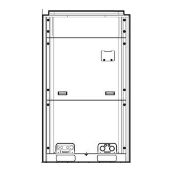
If the temperature is beyond the range, the safety protection measure of the unit may take effect, and the air conditioning unit will stop. 3 Preparation before Installation Note: The picture is only used for reference and the actual product prevails. Unit: mm. 3.1 Standard Parts Please use the following standard parts supplied by Gree. -
Page 10: Installation Site
D.C. Inverter Multi VRF Modular Parts for Outdoor Unit Number Name Picture Quantity Remarks Owner's Manual Must be connected to the last Wiring (match with IDU of communication resistance) connection Attach on the wired controller Mark (Master ) of master IDU or on the front panel 3.2 Installation Site Forbidden Items! It indicates that improper operation might lead to human casualty or... - Page 11 D.C. Inverter Multi VRF Modular 3.2.1 When the outdoor unit is totally surrounded by walls, please refer to following figures for space dimension. 3.2.1.1 Space dimension for single-module unit Fig. 3 3.2.1.2 Space dimension for dual-module unit Fig. 4 3.2.1.3 Space dimension for three-module unit Fig.5...
- Page 12 D.C. Inverter Multi VRF Modular 3.2.1.4 Space dimension for four-module unit Fig.6 3.2.2 When there is wall (or similar obstruction) above the unit, keep the distance between the unit top and the wall at least 300mm or above. When the unit is located in a totally open space with no obstructions in four directions, keep the distance between the unit top and wall at least 1500mm or above (See Fig.7).
- Page 13 D.C. Inverter Multi VRF Modular 3.2.3 Space dimension for multiple-module unit For keeping good ventilation, make sure there is no obstructions above the unit. When the unit is located at a half-open space (front and left/right side is open), install the unit as per the same or opposite direction.
-
Page 14: Piping Work Requirements
D.C. Inverter Multi VRF Modular 3.2.5 Take snow into consideration when installing the outdoor unit Fig.12 3.3 Piping Work Requirements There should be no fall among outdoor modules. Refer to the table below for piping work requirements. R410A Refrigerant System Outer Diameter (mm/inch) Wall Thickness (mm) Type... -
Page 15: Installation Instruction
D.C. Inverter Multi VRF Modular 4 Installation Instruction 4.1 Physical Dimension of the Outdoor Unit and Mounting Hole Outline and Physical Dimention of GMV-224WM/B-X and GMV-280WM/B-X unit Fig.13... - Page 16 D.C. Inverter Multi VRF Modular Outline and Physical Dimention of GMV-335WM/B-X, GMV-400WM/B-X and GMV-450WM/B-X unit Fig.14...
- Page 17 D.C. Inverter Multi VRF Modular Outline and Physical Dimention of GMV-504WM/B-X, GMV-560WM/B-X and GMV-615WM/B-X unit Fig.15...
-
Page 18: Connection Pipe
D.C. Inverter Multi VRF Modular 4.2 Connection Pipe 4.2.1 Schematic Diagram of Piping Connection Fig.16... - Page 19 D.C. Inverter Multi VRF Modular 4.2.2 Schematic Diagram of Piping Sequence GMV-224WM/B-X and GMV-280WM/B-X Fig.17 GMV-335WM/B-X, GMV-400WM/B-X and GMV-450WM/B-X Fig.18...
- Page 20 D.C. Inverter Multi VRF Modular GMV-504WM/B-X, GMV-560WM/B-X and GMV-615WM/B-X g.19 4.2.3 Allowable pipe length and drop height among indoor and outdoor units Y type branch joint is adopted to connect indoor and outdoor units. Connecting method is shown in the figure below. Remark: Equivalent length of one Y-type manifold is about 0.5m.
- Page 21 D.C. Inverter Multi VRF Modular L10: Length from the first branch to the farthest IDU; L11: Length from the first branch to the nearest IDU; Equivalent length of branch of IDU is 0.5m Allowable R410A Refrigerant System Fitting Pipe Value ≤1000 L1+L2+L3+L4+…+L9+a+b+…+i+j Total length (actual length) of fitting pipe...
- Page 22 Φ51.4 Φ25.4 GMV-2350WM/B-X Φ51.4 Φ25.4 GMV-2405WM/B-X Φ51.4 Φ25.4 GMV-2460WM/B-X (3) If the length between an IDU and its nearest branch is above 10m, then increase the size of the liquid pipe of IDU (only for the pipe size that is≤6.35mm).
- Page 23 D.C. Inverter Multi VRF Modular 4.2.4 Connection Pipe among Outdoor Modules Fig.21 Fig.22 Note: When the distance between outdoor units exceeds 2m, U-type oil trap should be added at low-pressure gas pipe. A+B10m. 4.2.5 Fitting pipe between Outdoor Unit and the First Manifold 4.2.5.1 For single module system, pipe size (between outdoor unit and the first manifold)is determined by that of outdoor unit.
- Page 24 D.C. Inverter Multi VRF Modular Pipe size of basic outdoor module is shown as follows: Pipe between ODU and the first branch of IDU Basic Module Gas Pipe(mm) Liquid Pipe(mm) Φ19.05 Φ9.52 GMV-224WM/B-X Φ22.2 Φ9.52 GMV-280WM/B-X Φ25.4 Φ12.7 GMV-335WM/B-X Φ25.4 Φ12.7 GMV-400WM/B-X Φ28.6...
- Page 25 D.C. Inverter Multi VRF Modular Select the branch of outdoor module Module’s capacity (C) Model Select the branch of outdoor 504≤C ML01/A module 4.2.5.3 Fitting pipe between two manifolds from basic modules Pipe size (between two manifolds from basic modules)is based on the total capacity of upstream modules.
- Page 26 D.C. Inverter Multi VRF Modular Fig.26 Pipe between ODU and the first branch of IDU Basic Module(single module) Gas Pipe(mm) Liquid Pipe(mm) Φ19.05 Φ9.52 GMV-224WM/B-X Φ22.2 Φ9.52 GMV-280WM/B-X Φ25.4 Φ12.7 GMV-335WM/B-X Φ25.4 Φ12.7 GMV-400WM/B-X Φ28.6 Φ12.7 GMV-450WM/B-X Φ28.6 Φ15.9 GMV-504WM/B-X Φ28.6 Φ15.9 GMV-560WM/B-X...
- Page 27 GMV-1750WM/B-X Ф44.5 Ф22.2 GMV-1800WM/B-X Ф41.3 Ф19.05 GMV-1845WM/B-X Ф44.5 Ф22.2 GMV-1908WM/B-X Ф44.5 Ф22.2 GMV-1962WM/B-X Ф44.5 Ф22.2 GMV-2016WM/B-X Ф44.5 Ф22.2 GMV-2072WM/B-X Ф44.5 Ф22.2 GMV-2128WM/B-X Ф44.5 Ф22.2 GMV-2184WM/B-X Ф44.5 Ф22.2 GMV-2240WM/B-X Ф44.5 Ф22.2 GMV-2295WM/B-X Ф44.5 Ф22.2 GMV-2350WM/B-X Ф44.5 Ф22.2 GMV-2405WM/B-X Ф44.5 Ф22.2 GMV-2460WM/B-X...
- Page 28 D.C. Inverter Multi VRF Modular 4.2.5.5 Manifold at indoor unit side Manifold at indoor unit side can be selected as per total capacity of downstream indoor unit(s). Refer to the following table. Fig.28 Total capacity of downstream indoor R410A Refrigerant System Model unit(s) C (kW) C≤20.0...
-
Page 29: Installation Of The Connection Pipe
D.C. Inverter Multi VRF Modular Φ12.7 Φ6.35 C≤5.6 Φ15.9 Φ9.52 5.6<C≤14.2 Φ19.05 Φ9.52 14.2<C≤22.4 Φ22.2 Φ9.52 22.4<C≤28.0 Φ25.4 Φ12.7 28.0<C≤40.0 Φ28.6 Φ12.7 40.0<C≤45.0 Φ28.6 Φ15.9 45.0<C≤68.0 Φ31.8 Φ19.05 68.0<C≤96.0 Φ38.1 Φ19.05 96.0<C≤135.0 Φ44.5 Φ22.2 135.0<C 4.2.5.7 Fitting pipe between indoor unit and manifold Manifold should be matched with fitting pipe of indoor unit. - Page 30 D.C. Inverter Multi VRF Modular (2) Weld the connection pipes between indoor and outdoor unit. Please strictly conform to the requirements for welding process. Rosin joints and pin holes are not allowable. (3) When laying the pipes, be careful not to deform them. The radius of bending parts should be more than 200mm.
- Page 31 D.C. Inverter Multi VRF Modular Fig.33 Total capacity of downstream indoor Y-type manifold Model unit(s) (X) X≤200 FQ01A/A 200<X≤300 FQ01B/A 300<X≤700 FQ02/A 700<X≤1350 FQ03/A 1350<X FQ04/A (4) Manifold is isolated by insulating material that can bear 120℃ or higher temperature. Manifold attached foam can not be taken as insulating material.
-
Page 32: Air Purging And Refrigerant Charge
D.C. Inverter Multi VRF Modular Fig.34 4) Manifold attached foam can not be taken as insulating material. 5) When wrapping the tape, the later circle should cover half of the former one. Don’t wrap the tape so tightly, otherwise the insulation effect will be weakened. 6) After wrapping the pipe, adopt sealing material to completely fill the hole so as to prevent wind and rain from entering the room. - Page 33 D.C. Inverter Multi VRF Modular How much additional refrigerant should be charged Total refrigerant charging amount R= Pipeline charging amount A + ∑charging amount B of every module (1) Pipeline charging amount Pipeline charging amount A= ∑Liquid pipe length×refrigerant charging amount of every 1m liquid pipe Diameter of liquid Φ28.6...
-
Page 34: Electric Wiring
D.C. Inverter Multi VRF Modular Suppose that A (Quantity of refrigerant added to connection pipe) = ∑ Length of liquid pipe x Quantity of refrigerant added to liquid pipe per meter) = 5kg R (Quantity of added refrigerant in total) = 5+0=5kg After confirming that there is no leakage from the system, when the compressor is not in operation, charge additional R410A with specified amount to the unit through the filling opening of the liquid pipe valve of the outdoor unit. - Page 35 D.C. Inverter Multi VRF Modular Circuit Circuit breaker Wire size of breaker capacity for Wire size of Model Basic models power supply capacity combined combined uni (mm units (A) 2.5×5 GMV-224WM/B-X GMV-224WM/B-X 2.5×5 GMV-280WM/B-X GMV-280WM/B-X 4.0×5 GMV-335WM/B-X GMV-335WM/B-X 6.0×5 GMV-400WM/B-X GMV-400WM/B-X 6.0×5 GMV-450WM/B-X...
- Page 36 10×5+10×5+10× GMV-2405WM/B-X 560+615+615+615 63+63+63+63 10+10+10+10 5+10×5 10×5+10×5+10× GMV-2460WM/B-X 615+615+615+615 63+63+63+63 10+10+10+10 5+10×5 Note:“280+400”: indicates the combination of GMV-280WM/B-X and GMV-400WM/B-X unit. Please refer to the following table for circuit breaker and circuit breaker for indoor units. Breaker listed in the table represents total capacity of breaker in one system.
- Page 37 D.C. Inverter Multi VRF Modular If indoor unit is equipped with auxiliary electric heater, select capacity of circuit breaker as per auxiliary electric heater, which requires special setting. Indoor unit models (with auxiliary Capacity of circuit Min. sectional area of Min.
- Page 38 D.C. Inverter Multi VRF Modular 1) water pipe, 2) gas pipe, 3) drainage pipe, 4)other places that are considered by professionals as unreliable. (5) Power cord and communication wire should be separated, with a distance of more than 20cm. Otherwise, system’s communication may not work well. Steps and graphic of power cord connection: (1) Knock off the cross-through opening that’s used for leading the external power cord, with the cross-through rubber ring on the opening.
-
Page 39: System Communication
D.C. Inverter Multi VRF Modular Wiring method for the power cord of GMV-504WM/B-X, GMV-560WM/B-X and GMV-615WM/B-X The external power cord should be fixed by wire clamps. The communi- -cation line passes throu- -gh the rubber ring The communication line passes through the rubber ring . - Page 40 D.C. Inverter Multi VRF Modular Fig.40 4.6.2 Communication mode of GMV5 Modular DC Inverter Units CAN bus mode is taken for communication between IDU and ODU and communication among IDUs. 4.6.3 Selection and connection mode of GMV5 communication material 4.6.3.1 Select communication material Note: if air conditioners are installed at places where there’s strong electromagnetic interference, the communication wire of IDU and wired controller must use shielded wire and the communication wire between IDU and IDU/ODU must use shielded twisted pair.
- Page 41 D.C. Inverter Multi VRF Modular 1. Total length of communication line Light/Ordinary can't exceed 250m. polyvinyl chloride 2. The cord shall be Circular cord (the L≤250 sheathed cord. 2×0.75~2×1.25 cores shall be twisted together). 60227-5:2007 (60227 IEC 52 3. If unit is installed in places with intense /60227 IEC 53) magnetic field or strong interference, it is necessary to use shielded wire.
- Page 42 D.C. Inverter Multi VRF Modular Fig.43 Fig.44 Fig.45 (2) All communication wires of GMV5 are connected by screws.
-
Page 43: Connection Method And Steps For System Communication
D.C. Inverter Multi VRF Modular Fig.46 (3) If a single communication wire is not long enough and needs to be connected, the connected joint must be welded or pressure-welded. Do not simply twist the wires together. 4.6.4 Communication address Auto addressing technology is adopted for GMV5 IDU and ODU. No need to set address codes manually. - Page 44 D.C. Inverter Multi VRF Modular Fig.47 Connection of single unit Fig.48 Connection of modular units Note: ①For modular outdoor units, if there are multiple outdoor modules, then the master unit must be the first outdoor module on the communication wire and should not connect with...
- Page 45 D.C. Inverter Multi VRF Modular IDU (master unit is set by SA8 of the outdoor main board). ②For modular outdoor units, if there are multiple outdoor modules, then indoor units must be connected with the last slave module of ODU (slave module is set by SA8 of the outdoor main board).
- Page 46 D.C. Inverter Multi VRF Modular Fig.52 Two wired controllers control multiple IDUs When two wired controllers control multiple IDUs, the wired controller can be connected to any one IDU, provided that the connected IDU is of the same series. Meanwhile, one and only one of the wired controllers must be set as a slave controller.
- Page 47 D.C. Inverter Multi VRF Modular Fig.53 Note: ①Wired controller and light board remote receiver can be used at the same time. ②When light board remote receiver is used, please use remote controller at the same time. 4.7.4 Communication connection of central controlling units Note:The centralized controller can be installed when it is necessary.
-
Page 48: External Electrical Wiring Diagram
D.C. Inverter Multi VRF Modular Fig.54 4.8 External Electrical Wiring Diagram Each unit should be equipped with a circuit breaker for short circuit protection and exceptional overload protection. Besides, a main circuit breaker shall be prepared for IDUs and ODUs in order to connect or disconnect power of the entire system. - Page 49 D.C. Inverter Multi VRF Modular Fig.55 Note: maximum number of IDU is based upon ODU capacity. For details, please refer to the introduction of units’ combination. 4.8.2 External wiring diagram of modular connection Fig.56...
-
Page 50: Check Items After Installation And Trial Run
D.C. Inverter Multi VRF Modular Note: maximum number of ODU (N) and maximum number of IDU (n) are based upon the combination type of ODU. For details, please refer to the introduction of units’ combination. 5 Check Items after Installation and Trial Run 5.1 Check Items after Installation Check Items Conditions Might Happen... - Page 51 D.C. Inverter Multi VRF Modular not. (6) Check the valve: For single-module unit, fully open the gas and liquid valve and close oil balance valve; For dual/three module unit, fully open the gas, liquid valve and oil balance valve. 5.2.2 Trial run 5.2.2.1 Notices (1) Before test operation, make sure unit is power on and compressor has been preheated for more than 8 hours.
- Page 52 D.C. Inverter Multi VRF Modular pipe or at least 70% of the needed refrigerant has been added. (6) Description of each stage of debugging progress: Description of each stage of debugging progress Debugging —— Progress code Status code code LED1 LED2 LED3 Meaning...
- Page 53 D.C. Inverter Multi VRF Modular components No error in outdoor components. Start light light light next progress. System detects error in indoor components. XXXX is the project no. of the faulted IDU. 3s later, relevant error XXXX/Error light light light code is displayed.
- Page 54 D.C. Inverter Multi VRF Modular Outdoor pipeline and valves are not light light light normal. System detects error in indoor pipeline. XXXX is the project no. of the faulted IDU. 3s later, error code U8 is displayed. light light XXXX/U8 light For example, IDU no.
- Page 55 D.C. Inverter Multi VRF Modular Code LED1 LED2 LED3 Progress Display Display Display Code Code Code status status status System doesn’t have master unit. Reset light light light master unit. 01_01 Set More than 2 master units are set. Reset up master light light...
- Page 56 D.C. Inverter Multi VRF Modular Quantity of 04_Confirm the Light Light connected blink quantity of IDUs IDUs If the quantity displayed is the same with actual quantity, then press SW7 confirmation button on the master unit to confirm it. Unit will start next progress: Debugging code Progress code Status code...
- Page 57 D.C. Inverter Multi VRF Modular Below is relevant error: —— Debugging code Progress code Status code LED1 LED2 LED3 Meaning progress Display Display Display Code code Code status status status 06_Detect Error System detects error in outdoor outdoor Light Light Light code components.
- Page 58 D.C. Inverter Multi VRF Modular —— Debugging code Progress code Status code LED1 LED2 LED3 Meaning progress Display Display Display Code code Code status status status 08_Confirm Preheat time for compressor is less than preheated Light Light Light compressor Step 13: progress 09 is “Refrigerant judgments before startup” If the refrigerant quantity inside the system meets the requirement of operation startup, system will display as below and start next progress.
- Page 59 D.C. Inverter Multi VRF Modular 10_Status judgments of Light Light Light Outdoor valves are not fully turned on. outdoor valves before startup Then check the big and small valves whether they are fully turned on. After the check, press SW6 return button to restart the judgments. If unit detects that valve status is normal, it will display as below and start next progress.
- Page 60 D.C. Inverter Multi VRF Modular LED1 LED2 LED3 progress Display Display Display Code code Code status status status Debugging is enabled in cooling mode Light Light Light (debugging mode, auto-selected by system). Error Error occurs during debugging in Light Light Light code cooling mode.
- Page 61 D.C. Inverter Multi VRF Modular Debugging is finished. System is on 17_Debugging 01-04 Light Light Light standby condition. LED1 displays module finished address. LED2 and LED3 display “OF”. Step 19: after debugging is finished, some functions can be set up according to project’s actual needs.
-
Page 62: Common Malfunction And Troubleshooting
D.C. Inverter Multi VRF Modular ●Normal bus voltage is 1.414 times of power voltage. For Inverter compressor 1 example, if 3-phase power voltage is 390v, then the bus voltage after rectification is: 390v X 1.414=551v. It’s normal driven bus voltage if actual voltage varies 15v from the calculated voltage. - Page 63 Otherwise, there will be collision malfunction of the project codes. For detail operation methods, please refer to the GMV5 Installation and Maintenance Manual. ②If problem can not be solved after checking the above items, please contact Gree service center and show phenomena and models. Following circumstance are not malfunction.
-
Page 64: Error Indication
D.C. Inverter Multi VRF Modular The room odor absorbed by the unit is blew The unit emits odor Operating out again Indoor unit still Indoor fan motor will keep running 20-70s so After every indoor unit receive "stop" signal, fan runs after switch as to take good use of excess cooling and will keep running... - Page 65 D.C. Inverter Multi VRF Modular DC Inverter VRF Units...
-
Page 66: Maintenance And Care
(6) Check if the outdoor unit is installed firmly. If there is something abnormal, please contact the GREE appointed service center. 8.4 Maintenance after Seasonal Use (1) Cut off main power supply of the unit. -
Page 67: Parts Replacement
Gree. Warranty should meet the folowing requirements: (1) First run of the unit should be operated by professional personnel from Gree appointed service center. (2) Only Gree manufactured accessories can be used on the machine. - Page 68 GREE ELECTRIC APPLIANCES, INC. OF ZHUHAI Add: West Jinji Rd, Qianshan, Zhuhai, Guangdong, China, 519070 Tel: (+86-756) 8522218 Fax: (+86-756) 8669426 E-mail: gree@gree.com.cn www.gree.com...
Need help?
Do you have a question about the GMV-2460WM/B-X and is the answer not in the manual?
Questions and answers