
Related Manuals for Automatic Technology Axess Pro Series


Summary of Contents for Automatic Technology Axess Pro Series
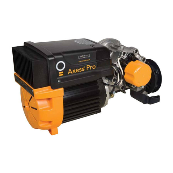
- Page 1 ® Axess Pro Series 3100 Industrial Roller Shutter Opener Featuring TrioCode ™ Technology Technical Document Installation Manual 1.11 14 Dec 2011 English Part # 13296 (Manual) INSTALLATION INSTRUCTIONS | OWNERS COPY...
- Page 2 Automatic Technology (Australia) Pty Ltd to the extent that such may be lawfully excluded hereby expressly disclaims all conditions or warranties, statutory or otherwise which may be implied by laws as conditions or warranties of purchase of an Automatic Technology (Australia) Pty Ltd industrial roller shutter opener.
-
Page 3: Table Of Contents
Axess ® Pro Series 3100 1-Phase 240Vac Industrial Roller Shutter Opener Important Safety Instructions Features Package Contents Controllers Input And Output Operating Controls Before Drive Unit Installation Installation Manual Console EasyBeam™ Installation Viewing And Editing Parameters Setting Limits with Logic Console Setting Limits: Via Transmitter Menu Structure Coding Transmitters... - Page 4 Features Thank you for purchasing the Axess® Pro Series 3100 Industrial Roller Shutter Opener. This opener is designed to suit heavy duty rolling shutters. The components and materials used in this opener are of the latest technology and highest quality. Listed below are some of the many features.
- Page 5 Soft-Start Soft-Stop The opener accelerates slowly at the start of the cycle and deaccelerates just before reaching the limit. This feature reduces the wear and tear on the shutter. Security Code Store The opener uses state of the art technology to store your selected transmitter codes.
-
Page 6: Important Safety Instructions
Important Safety Instructions WARNING: It is vital for the safety of those who install, maintain or operate the opener to follow all instructions. Failure to comply with the instructions may result in serious personal injury and/or property damage. Please read this installation instruction manual before attempting to install, maintain or use the opener. -
Page 7: Package Contents
Package Contents Description Axess 3100 Power Drive Unit Timing Assembly Logic Console* Manual Console* Communication Cable Output Drive Shaft Assembly Chain 10B (0.625”) Sprocket 14T (0.625”) Mounting Flange Ax30 Fastener Pack TrioCode™ Keyring Transmitters* EasyBeam™ with wires and brackets* Installation Manual Communication Cable Timing assembly Logic Console... -
Page 8: Controllers Input And Output
Controller Input And Outputs fi g WARNING! HIGH VOLTAGE! Motor identifi cation harness connector This unit user serviceable. Disconnect power supply before removing Clutch interlock microswitch connector cover. Please ensure all electrical cables are secured clear of any moving parts. Serial interface connector Failure to comply may cause electrocution resulting in serious injury or death. -
Page 9: Operating Controls
Operating Controls fi g Manual Console Logic Console Programmer PG-3 Input Terminal Block ( From Left To Right ) Console Previous Button V+ Three Wire P.E. Beams “ + “ Supply Liquid Crystal Display IN3 Three Wire P.E. Beams Trigger Input Console Next Button V- Common For Two Wire EasyBeam™... -
Page 10: Before Drive Unit Installation
Before Drive Unit Installation The Axess® Pro Series 3100 is designed to operate most industrial heavy duty roller shutters. The shutter must be in good working condition and travel freely in the guides. fi g Step 1 - Initial Check Before commencing installation, check the following: The shutter moves freely for the full travel in both directions. -
Page 11: Installation
Installation Step 3 - Mounting The Drive Unit Open the shutter about one metre from the fl oor. Raise the drive unit to the required height by using a suitable lifter or use chain block connected to a secure beam above the shutter axle. Position opener and secure with four M12x30 screws. -
Page 12: Manual Console
Manual Console The manual console has open, close, stop and set push buttons. The status of the door is indicated by the LED lights. The manual console only supports Safety Close mode. In this mode, the user must press and hold the close button to close the door. -
Page 13: Easybeam™ Installation
Repeat steps a and b to assemble the EasyBeam™ receiver. Locate the EasyBeam™ in a strategic location in the doorway. Automatic Technology recommends that the sensor is placed 100mm above the fl oor level and as close as possible to the shutter opening. Connect as per the wiring diagram (Fig. - Page 14 Viewing & Editing Logic Console This section illustrates how to locate, view and View Mode (No cursor) adjust parameters in the logic console unit. Parameter name Parameter number in sub menu Locating parameters 2: 100% O/L Time Refer to MENU STRUCTURE on Page 15 or the preceding Parameter (sec) section for CONTROL BOARD ADJUSTMENTS.
-
Page 15: Setting Limits With Logic Console
Setting Limits via Logic Console Step 7 - Setting Travel Limits To Desired Turn on the power to the opener. The controller will CLOSE Limit, go through a start up sequence. After a short delay the MAIN SCREEN (Fig. 16) will be displayed. -
Page 16: Setting Limits Via Transmitter
Setting Limits via Transmitter In order to use a transmitter to set the limits, it must fi rst have at least one of its buttons coded to the logic console. The function assigned to the transmitter’s buttons is of MENU 1 no concern here as the buttons are temporally assigned Code Transmitter to OPEN, CLOSE and SET... -
Page 17: Menu Structure
Logic Console Menu Structure Menu structure NOTES 1. Press PREV/NEXT buttons move to Left/Right. 2. Press OPEN/CLOSE buttons to change setting. 3. Press SET button to save changes. 4. Press STOP to return to are pressed. MENU without saving changes 5. -
Page 18: Coding Transmitters
Coding Transmitter The Axess ® Pro Series 3100 can store 511 transmitters in its memory. Each transmitter can be allocated an alpha- ID/SN display indicator I.D label/Serial number numeric ID label up to eleven characters in length and each button can be assigned to one of several control Store number fi... -
Page 19: Transmitter Editing
Transmitter Editing Display Transmitter Record MENU 1 Using one of the methods below, you can display the Code Transmitter required transmitters details. fi g Navigating To “Edit Transmitter” Menu Press NEXT to navigate to Menu 1 (Fig. 26) PR E S S Press SET to enter the transmitter edit procedure. - Page 20 Transmitter Editing Editing The Store Location 14 I [No Name] This feature is only available when coding the fi rst button OSC PED LGT VAC of a new transmitter. Press NEXT or PREV to move the cursor over Store fi g PRESS (Fig.
-
Page 21: Transmitter Management
Transmitter Management The Axess ® Pro Series 3300 provides a transmitter listing MENU 1 facility which enables the User to fi nd a transmitter Code Transmitter location within the memory. Once located a stored transmitter can be replaced, deleted, edited, copied PRESS fi... - Page 22 Transmitter Management Code Operation (location used) MENU 1.2 If the code operation is selected for a location that already Delete contains a transmitter, then the storing transmitter code procedure (page 19) will be initiated and the new transmitter will replace the existing one. Note the button fi...
-
Page 23: Remotely Coding Transmitters
Remotely Coding Transmitters If a transmitter is already coded into the opener, additional transmitters can be coded without being in direct contact with the opener’s control panel. PRESS Existing NOTE: Only the function of the existing transmitter transmitter button can be assigned to new transmitter. Please fi... -
Page 24: Setting Pedestrian Position
Setting Pedestrian Position Pedestrian Access Position After completing the limit setup procedure the Pedestrian MENU 10.3 Access position is automatically set to a position which Set Pedestrian is approximately in the middle of the shutter travel. The position can be manually set by following the SETTING PEDESTRIAN POSITION procedure. -
Page 25: Reprofi Ling The Shutter Travel
Re-profi le The Shutter Travel To Recalculate Travel Times Reprofi ling is a simplifi ed way of re-learning the travel characteristic of a previously setup Limit Switch travel installation. Re-profi ling can be used when the travel characteristics of the shutter change due to mechanical adjustments etc. -
Page 26: Control Board Adjustments
Details about the four This mode is selected by entering a non-zero time for Auto-Close modes follow. Automatic Technology the “P.E. Ped’n A/C” parameter. This mode is the strongly recommend using a P.E. Beam for added same as the P.E. - Page 27 Control Board Adjustments Parameter Default Step Unit Menu No. STD AUTO-CLOSE TIME 300.0 Sets and enables the standard Auto-Close time. P.E. AUTO-CLOSE TIME Sets and enables the 60.0 P.E. triggered Auto-Close time. PEDESTRIAN AUTO-CLOSE TIME Sets and 60.0 enables the Pedestrian Auto-Close time. P.E.
-
Page 28: Motor Settings
Control Board Adjustments Menu 5. Motor Settings Motor Speed The motor speed is controlled by the OPEN AND CLOSE SPEED FREQUENCY parameter. The default value is the maximum recommended for normal operation. If, however, the shutter moves too quickly or too slowly for a particular installation, the frequency can be reduced or increased to make the motor run slower or faster. - Page 29 Control Board Adjustments When GPI Selected As OSC: If the shutter is moving the activation of the GPI input or by a transmitter button with the OSC function assigned will cause the shutter to stop. The next trigger will move the shutter in the opposite direction to the last direction travelled.
- Page 30 This parameter enables activity report outputs. Contact Automatic Technology for more details. Menu 6.14 Activity Report ID This parameter sets the ID of the logic console that is sent with the activity report. Contact Automatic Technology for more details. Menu 6.15 Vacation Mode Vacation Mode blocks all but one designated remote control transmitter from activating the Axess®...
- Page 31 Control Board Adjustments Parameter Default Step Unit Menu Safety Close Mode P.E. Beams INPUT RESPONSE MODE Sets the P.E. OPN & CLS stop CLS to response mode. Options are OPEN and CLOSE CLS to stop reverse cycles stop, Close cycles stop or Close cycle reverse CLS to reverse PE REVERSE TIME FULL...
-
Page 32: Time Clock
Time Clock The opener provides a programmable time clock which MENU 7.1 can be used to control the Axess® Pro Series 3100 on Set Time/Date a timed basis at various times of the week. This section details the time clock operation and confi guration. fi... - Page 33 Time Clock The selectable functions available are: When GPI Input Is Confi gured As PED: The activation of the GPI input or by pressing a RX = Off transmitter button with PED function assigned From the time when the program with RX = OFF is will open the shutter partially to allow pedestrian activated, all the transmitters will be disabled.
-
Page 34: Diagnostic Tools
Diagnostic Tools The logic console provides several diagnostic tools MENU 8 from within the Diagnostics Menu (Menu 8). This Diagnostics section details the function of each tool and its use. fi g Navigating To Diagnostics Menu 1. Press PREV to navigate to Menu 8 (Fig. - Page 35 Diagnostic Tools Menu 8.5 Service Counter Service Counter The opener provides a periodic service counter which (Cycles) 60000 can be set to expire after a number of drive cycles. When expired the opener will beep three times at fi g the beginning of each drive cycle and a message will be displayed on the MAIN SCREEN (Fig.
-
Page 36: Memory Tools
Memory Tools Menu 9.0 Memory Tools The Memory Tools accessed from within Menu 9 are used to clear the transmitter codes from the openers memory and clear the controller’s memory. Once selected the PREV or NEXT buttons can be used to view the Memory Tool options. -
Page 37: Specifi Cations
Specifi cations Technical Specifi cations Power supply 230V - 240Va.c. 50Hz Motor type Three Phase 240 Volts (Delta Connection) Model AX3105 Motor power 0.5 HP Maximum shutter opening: 18 m² Model AX3110 Motor power 1.0 HP Maximum shutter opening: 36 m² Opener Limits Travel 21 turns of output shaft Duty Cycle... -
Page 38: Troubleshooting
Troubleshooting Symptom Possible cause Remedy Mains power not switched on. Switch on mains power. Communication cable not Connect the communication cable. Blank display screen. connected. Controls cover is lose or missing. Install the controls cover. Logic console displays “Drive Hand chain is not freely hanging. Free the hand chain. -
Page 39: Maintenance
Maintenance Yearly The shutter should be tested manually regularly to Automatic Technology suggests you contact your ensure it is in good condition. A poorly maintained industrial roller shutter professional to perform an annual shutter could cause fatal or serious injuries or serious shutter service. -
Page 40: Spare Parts
Spare Parts Axess® Pro Series 3100 Owner Installation Instructions... -
Page 41: Warranty
Warranty and Exclusion of Liability 1. This Warranty is given by Automatic Technology (Australia) (e) theft, fi re, fl ood, rain, water, lightning, storms or any other acts of Pty Ltd (ABN 11 007 125 368) (ATA). 6-8 Fiveways Boulevard, God;... - Page 42 © December 2011 Automatic Technology (Australia) Pty Ltd. All rights reserved. Axess®, TrioCode™and EasyBeam™ are trademarks of Automatic Technology (Australia) Pty Ltd. No part of this document may be reproduced without prior permission. In an ongoing commitment to product quality we reserve the right to change specifi cation without notice.
Need help?
Do you have a question about the Axess Pro Series and is the answer not in the manual?
Questions and answers