
Related Manuals for Renishaw ATOM Series


Summary of Contents for Renishaw ATOM Series
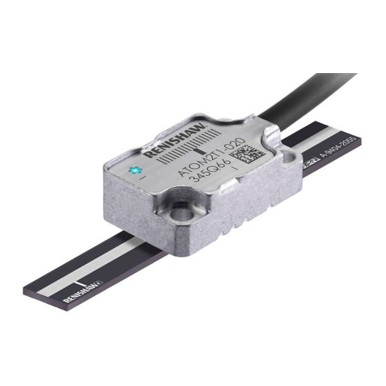
- Page 1 Installation guide M-9693-9723-06-A ATOM linear encoder systems RSLM high accuracy linear encoder ™...
-
Page 2: Table Of Contents
Contents Legal notices Calibration overview Storage and handling System calibration ATOM system installation overview Restoring factory defaults RTLF / RKLF tape scale Switching Automatic Gain Control (AGC) on or off LED diagnostics RTLF installation drawing RKLF installation drawing Troubleshooting RTLF / RKLF application methods ATOM readhead RTLF ledge or dowel mounting Cabled readhead dimensions... -
Page 3: Legal Notices
Features of Renishaw’s encoder systems and similar products are the subjects of the following patents and patent applications: The user is cautioned that any changes or modifications not expressly approved by Renishaw plc or authorised representative could void the user’s authority to operate the equipment. - Page 4 (SVHCs) is available at WEEE recycling guidelines The use of this symbol on Renishaw products and /or accompanying documentation indicates that the product should not be mixed with general household waste upon disposal. It is the responsibility of the end user to dispose of this product at a designated collection point for waste electrical and electronic equipment (WEEE) to enable reuse or recycling.
-
Page 5: Storage And Handling
Storage and handling Scale Minimum storage bend radius RTLF – 150 mm RKLF – 50 mm NOTE: During storage, ensure self-adhesive tape is on the outside of bend. RCLC scale only Storage Installation Operating Humidity (RKLF) Scale and readhead +70 °C +35 °C +70 °C −20 °C +10 °C 0 °C... -
Page 6: Atom System Installation Overview
For information on designing the readhead and scale into the system refer to the detailed installation drawings and 3D models at or contact your local Renishaw representative. IMPORTANT: Prior to installing readhead and scale, installation drawings should be reviewed to ensure the correct orientation of the readhead relative to the scale. -
Page 7: Rtlf / Rklf Tape Scale
Overall length (with optional end covers) = Measuring length + 50 mm 2.5 ±0.055 (20 µm version) Scale length (with optional end covers) = Measuring length + 13 mm Scale length (without end covers) = Measuring length + 6 mm For detailed installation drawings refer to www.renishaw.com/atomdownloads ATOM linear installation guide... -
Page 8: Rklf Installation Drawing
RTLF / RKLF tape scale (continued) Dimensions and tolerances in mm RKLF installation drawing 40 µm version For dimensioned cabled and FPC readhead drawings see page 33 page ( Yaw tol. ±1°) 0.36 (Roll tol. ±1°) 0.22 20 µm version ( Yaw tol. ±0.5°) 0.18 Reference mark Set-up LED... -
Page 9: Rtlf / Rklf Application Methods
RTLF / RKLF tape scale (continued) RTLF / RKLF application methods RTLF / RKLF scale application depends upon scale length and bracket type. RTLF / RKLF tape scale Application Mounting (RTLF / RKLF any length) (RTLF < 500 mm only) Adjustable bracket Fixed mounting Readhead mounting is integral to the machine and Ledge or dowel mounting... -
Page 10: Rtlf Ledge Or Dowel Mounting
RTLF ledge or dowel mounting Suitable for: RTLF tape scale < 500 mm long Required parts: Optional parts: Appropriate length of RTLF scale (‘RTLF installation drawing’, page 5) Renishaw scale wipes (A-9523-4040) Appropriate cleaning solvents (‘Storage and handling’, page 3) Loctite dispensing tip (P-TL50-0209) ® ™... -
Page 11: Rtlf Mounting (For Lengths < 500 Mm Only)
Allow substrate to dry before applying scale. * If dowels or ledge are permanent, their maximum height above substrate is 0.6 mm. Clean scale using Renishaw scale wipes or Fit datum clamp and end covers (page 12) and, a clean, dry, lint-free cloth. -
Page 12: Rtlf / Rklf Scale Applicator
Readhead mounting bracket and scale applicator: There are different versions of the applicator depending upon the scale and design of the readhead mounting bracket. For more information on designing your bracket, contact your local Renishaw representative. Slim applicator Side mount applicator... -
Page 13: Rtlf / Rklf Application (Any Length)
Remove the applicator and, if necessary, adhere the remaining scale manually. Slim and side mount applicators: Fit readhead mounting bracket after removal of scale applicator. Clean the scale using Renishaw scale wipes or a clean, dry, lint-free cloth. RTLF: Fit datum clamp and end covers (page 12) -
Page 14: Rtlf Datum Clamp
RTLF / RKLF tape scale (continued) RTLF datum clamp RTLF end covers The end cover kit is designed to be used with RTLF scale to provide protection for exposed scale ends. The datum clamp fixes the RTLF scale rigidly to the substrate at the location chosen. NOTE: End covers are optional and can be fitted before or after readhead installation. -
Page 15: Rklf End Clamps
RKLF end clamps The end clamp kit is designed to be used with Renishaw RKLF scale to ensure the scale is mastered to the RTLF and RKLF scale > 100 mm in length has reference marks every 50 mm. Stickers can be used to substrate. -
Page 16: Rclc Glass Spar Scale
Operating rideheight: 2.5 ±0.11 (40 µm version) Overall length (L) (20 µm version) 2.5 ±0.055 Measuring length Can be applied on one or both sides of the scale. For detailed installation drawings refer to www.renishaw.com/atomdownloads ATOM linear installation guide... -
Page 17: Rclc Mounting
(continued) RCLC mounting Suitable for: RCLC glass spar scale, any length Optional parts: Required parts: Renishaw scale wipes (A-9523-4040) RCLC scale (‘RCLC installation drawing’, page 14) RGG-2 two part epoxy adhesive (A-9531-0342) Lint-free cloth Appropriate cleaning solvents (‘Storage and handling’, page 3) - Page 18 Apply fillet of RGG-2 two part epoxy adhesive. After 24 hours when epoxy is cured, clean Support Epoxy can be applied to one or both sides of the scale using Renishaw scale wipes or a clean, dowels scale. Ensure epoxy does not wick onto scale surface. dry, lint-free cloth.
-
Page 19: System Connection Readhead Only (No Interface)
AGC on /off or restore factory defaults. See page 36 for pin-out information. Contact your local Renishaw representative for more information regarding FPC design requirements. Calibration is an essential part of system set-up that optimises the incremental signals and phases the reference mark. See page 28 for information on the calibration routine. - Page 20 System connection (continued) Approved ESD precautions must be followed at all times during readhead electrical connection. NOTE: The FPC cable must be connected before fitting the readhead lid. The lid is secured by the readhead mounting screws. Inserting the FPC cable Ensure the locking lever is up (open) before Applying pressure to the whole locking lever, When the system has been connected, proceed...
-
Page 21: Aci Interface
Ensure 100% shielding Maximum exposed conductor strip length 2.5 mm (to ensure isolation from the body) Contact your local Renishaw representative for more information regarding FPC design requirements. Ground the mounting brackets Shielding Use a metal clamp around the cable ferrule to ground the readhead cable ... - Page 22 Maximum exposed conductor strip length 2.5 mm (to ensure isolation from the body) Ensure 100% shielding Contact your local Renishaw representative for more information regarding FPC design requirements. Ground the mounting brackets Shielding Use a metal clamp around the cable ferrule to ground the readhead cable ...
-
Page 23: Ri Interface
NOTE: An optional Ri cable guide (A-9693-2577) is available to simplify assembly. For instructions on how to install the Ri cable guide, download Ri interface cable guide (Renishaw Re-assemble the housing ensuring part no. M-9770-9478) from the website at the cable ferrule is located in the Ensure ferrule www.renishaw.com/atomdownloads... -
Page 24: Ti Interface
System connection (continued) Ti interface Disconnecting the readhead Approved ESD precautions must be followed at all times during readhead Disconnect power. and interface electrical connection. Remove the cover plate on the interface (two M2.5 hex head screws). The readhead is connected to the Ti interface via a small, rugged interboard connector to allow for Gently lever the connector PCB easy feed-through during installation. -
Page 25: Readhead Mounting And Alignment Methods
There is a range of tools available to assist with readhead installation depending upon the system design; these are detailed below. For more details on designing the mounting bracket and selecting the appropriate mounting tools, contact your local Renishaw representative. Ensure that the scale, readhead optical window and mounting face are clean and free from obstruction. -
Page 26: Shim Kit
DTi adapter the distance to the scale surface. Contact your local Renishaw representative Shims of a known thickness are inserted between the mounting face of the for details of the DTi adapter and digital readhead and the bracket to give the correct rideheight. -
Page 27: Dummy Kit
Side mount bracket (A-9401-0103) , ‘L ’ mount bracket (A-9402-0037) or customer designed bracket * 2 × bracket mounting screws ATOM readhead * The bracket should have a shoulder to control readhead yaw. Contact your local Renishaw representative for more information on bracket design. Remove the dummy head. -
Page 28: Accurate Bracket And Feeler Gauge
Applications where the readhead mounting bracket allows full adjustment of the readhead and the a bracket thickness of 2 ±0.02 mm Renishaw USB set-up tool kit and software or an oscilloscope can be used to monitor the output signals. Required parts: Required parts: ‘L’... -
Page 29: Calibration Overview
Calibration overview Calibration is an essential operation that completes readhead set-up, with the optimum incremental and reference mark signal settings stored in the readhead’s non-volatile memory. This section is an overview of the calibration procedure for an ATOM system. For more detailed information on calibrating the system see ‘System calibration’, page Ensure AGC is switched off. -
Page 30: System Calibration
System calibration Calibration (CAL) is an essential operation that completes readhead set-up, with the optimum incremental and reference mark signal settings stored in the readhead’s non-volatile memory. Before system calibration: Clean the scale and readhead optical window If reinstalling, restore factory defaults (‘Restoring factory defaults’, page 29) ... -
Page 31: Restoring Factory Defaults
Restoring factory defaults When realigning the readhead, reinstalling the system, or in the case of continued calibration failure, factory defaults should be restored. To restore factory defaults: Switch the system off, then switch on again using the following methods depending on interface used. No interface ACi interface Ri interface... -
Page 32: Led Diagnostics
Alarm output will take the form of 3-state or line driven E− signal depending on interface configuration. Also, some configurations do not output overspeed alarm. See ATOM miniature encoder system data sheet (Renishaw part no. L-9517-9563) for more details. ™... -
Page 33: Troubleshooting
Check that the readhead variant is the correct type for the chosen scale (see the ATOM ™ miniature encoder system data sheet (Renishaw part no. L-9517-9563) for details of readhead configuration). Check that the readhead variant is the correct type for the chosen scale (see the ATOM miniature encoder system data sheet (Renishaw part no. - Page 34 Check that the readhead variant is the correct type for the chosen scale (see the ATOM miniature encoder system data sheet (Renishaw part no. L-9517-9563) for details of readhead configuration). ™ Ensure you are not over-speeding the readhead during calibration mode (maximum speed < 100 mm / sec)
-
Page 35: Atom Readhead
R> 20 Dynamic bend radius R> 10 Static bend radius 5 min Identification marks for readhead manufacture only. Notches will vary depending on readhead type. For detailed installation drawings, refer to www.renishaw.com/atomdownloads * Not optical centreline ATOM linear installation guide... -
Page 36: Fpc Readhead Dimensions
Identification marks for readhead manufacture only. Notches will vary depending on readhead type. NOTE: Readhead is supplied with lid separate. FPC cable must be inserted before fitting the lid. www.renishaw.com/atomdownloads For detailed installation drawings, refer to * Not optical centreline... -
Page 37: Bracket Dimensions
ATOM readhead (continued) Dimensions and tolerances in mm Bracket dimensions ‘ L’ mount bracket Side mount bracket (A-9402-0037) (A-9401-0103) 16.25 3 holes 10.5 M2 × 0.4 Ø9.15 10.5 12.7 4.85 Ø9.4 3 holes 8.25 M2 × 0.4 16.5 16.5 3.25 2 holes M3 ×... -
Page 38: Output Signals
ATOM readhead (continued) Output signals † Interboard connector 15-way D-type (on interboard) Function Signal Colour Brown 9, 10 4, 5 Power * White 3, 6, 11, 14 12, 13 Cosine − Blue Incremental Yellow Sine − Green Violet Reference mark −... -
Page 39: Aci Interface
ACi interface FPC variant Input signals Installation drawing Dimensions and tolerances in mm Pin 1 Pin 16 † ACi FPC input connector FPC input connector CAL pad JST output Signal Function Component area connector * 7, 8 14.5 ‡ Power 3, 6, 11, 14 12.5 −... -
Page 40: Cable Variant
ACi interface (continued) Cable variant Input signals Installation drawing Dimensions and tolerances in mm ‡ Interboard (on interboard) connector (T) Cable input connector Function Signal Colour CAL pad JST output connector * Component area Brown 14.5 Power † White Cosine − Blue Incremental Yellow... -
Page 41: Pcb Mounting Variant
ACi interface (continued) PCB mounting variant Installation drawing ACi PCB mounting variant interface (digital output only) Dimensions and tolerances in mm Input Output 16.1 Function Signal Signal 10.1 CAL pad Power 12.5 − − Incremental − − Reference mark − −... - Page 42 ACi interface (continued) Speed 20 µm system Maximum speed (m/s) Lowest recommended counter input frequency 0020 0040 0080 0100 0200 0400 1000 2000 (MHz) (1 µm) (0.5 µm) (0.25 µm) (0.2 µm) (0.1 µm) (50 nm) (20 nm) (10 nm) 0.35 0.13 0.065 0.18...
-
Page 43: Ri Interface
Ri interface Installation drawing Output signals Dimensions and tolerances in mm Digital Function Signal 7, 8 Power * 2, 9 − Incremental 33.3 4-40 unc × 2 − Reference mark − † Alarm − Set-up Shield Case Do not connect 10, 15 CAL button Analogue... - Page 44 Ri interface (continued) Speed Clocked outputs Ri0100, Ri0200 and Ri0400 interfaces have clocked outputs. Customers must ensure they comply with the lowest recommended counter input frequency. Maximum speed (m/s) 20 µm system 40 µm system Lowest recommended counter input frequency (MHz) 0100 0200 0400 0100...
-
Page 45: Ti Interface
Ti interface Installation drawing Output signals Dimensions and tolerances in mm Digital Function Signal 7, 8 Power * 2, 9 − Incremental 33.3 4-40 unc × 2 − Reference mark − Alarm † − Set-up Shield Case Do not connect 10, 15 Analogue Function... - Page 46 Ti interface (continued) Speed 20 µm system Maximum speed (m/s) Lowest recommended counter input frequency 0004 0020 0040 0100 0200 0400 1000 2000 4000 10KD 20KD (MHz) (5 µm) (1 µm) (0.5 µm) (0.2 µm) (0.1 µm) (50 nm) (20 nm) (10 nm) (5 nm) (2 nm)
-
Page 47: Electrical Connections
Cable Z = 120R 120R Shield (recommended) A B Z E− 220 pF For more information on FPC contact your local Renishaw representative. 0 V Standard RS422A line receiver circuitry. Customer Capacitors recommended for improved noise immunity. electronics Cable readhead Connector / interface... -
Page 48: Output Specifications
Output specifications Analogue output signals All ATOM readheads and Ri and Ti analogue interfaces. Incremental 2 channels V and V differential sinusoids in quadrature, centred ~ 1.65 V (90 ° phase shifted) 40 / 20 µm 0.7 to 1.35 Vpp with Green LED +) −... - Page 49 Output specifications (continued) Digital output signals Form – Square wave differential line driver to EIA RS422A. All ACi interfaces, Ri interfaces and Ti digital interfaces. Incremental * 2 channels A and B in quadrature (90 ° phase shifted) Signal period Resolution Reference * Synchronised pulse Z, duration as resolution...
-
Page 50: General Specifications
= ~ 10.1 μm/m/°C substrate scale use extreme install scale CAUTION: Renishaw encoder systems have been designed to the relevant EMC standards, but must be correctly integrated to achieve EMC compliance. In particular, attention to shielding arrangements is essential. ATOM linear installation guide... -
Page 51: Scale Specifications
Accuracy ±3 µm (at 20 °C) Coefficient of thermal expansion ~8 µm/m/°C Length (mm) 10, 18, 30, 55, 80, 100, 105, 130 Mass 13.9 g/m * For information on how the substrate affects the axis, contact your local Renishaw representative. ATOM linear installation guide... - Page 52 New Mills, Wotton-under-Edge uk@renishaw.com Gloucestershire, GL12 8JR United Kingdom www.renishaw.com www.renishaw.com/contact For worldwide contact details, visit *M-9693-9723-06* Renishaw plc. Registered in England and Wales. Company no: 1106260. Part no.: M-9693-9723-06-A Registered office: New Mills, Wotton-under-Edge, Gloucestershire, GL12 8JR, UK. Issued: 09.2020...
Need help?
Do you have a question about the ATOM Series and is the answer not in the manual?
Questions and answers