Table of Contents
Advertisement
Advertisement
Table of Contents

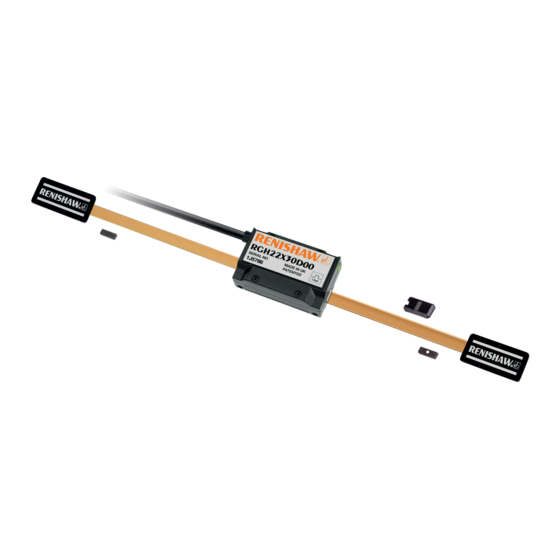
Summary of Contents for Renishaw RGH22
- Page 1 Installation guide M-9531-9818-01-B RGH22 RGS20 linear encoder system...
-
Page 2: Table Of Contents
Contents Product compliance Storage and handling RGH22 readhead installation drawing RGS20 scale installation drawing Scale application End clamps Reference mark and limit switch actuator installation Readhead mounting and alignment Reference mark set-up Limit switch Output signals Speed Electrical connections Output specifications... -
Page 3: Product Compliance
It is the responsibility of the end user to Further information relating to the RGH22 encoder range can be found in the RGH22 encoder system dispose of this product at a designated collection point for waste electrical and electronic equipment (WEEE) Data sheet (L-9517-9676). -
Page 4: Storage And Handling
Storage Operating Humidity System System 95% relative humidity +70 °C +55 °C (non-condensing) −20 °C 0 °C to EN 60068-2-78 Minimum bend radius RGS20 – 100 mm NOTE: Ensure self-adhesive tape is on outside of bend. RGH22 RGS20 installation guide... -
Page 5: Rgh22 Readhead Installation Drawing
RGH22 readhead installation drawing Dimensions and tolerances in mm Reference mark sensor position R>50 dynamic bend radius Optical centre R>10 static bend radius 11.6 Reference mark actuator ‡ >6 2 holes M3 x 0.5 x 9.5 deep Epoxy mounted (A-9531-0250) †... -
Page 6: Rgs20 Scale Installation Drawing
Reference mark sensor position (inside readhead) NOTE: The surface roughness of the scale mounting surface must be ≤3.2 Ra. The parallelism of the scale surface to the axis of motion (readhead rideheight variation) must be within 0.05 mm. RGH22 RGS20 installation guide... -
Page 7: Scale Application
When installing RGS20-P scale use applicator kit (A-9531-0280). Clean scale using Renishaw scale cleaning wipes (A-9523-4040) or a clean, dry, lint-free cloth. For instructions on how to use the RGA22 please refer to the ‘RGA22 scale applicator User’s guide’ (M-9531-0297). -
Page 8: Reference Mark And Limit Switch Actuator Installation
An external set-up signal (X or V ) is also available on RGH22 readheads for use where the LED is not Ensure that excess glue does not enter the reference mark actuator adjustment mechanism. -
Page 9: Reference Mark Set-Up
Reference mark set-up Output signals RGH22 D, X, Z, Y, H, P, Q, R, S, RS422A digital To ensure unidirectional repeatability, the reference mark requires phasing with the scale in the direction of normal datuming operation. 15 way D-type 16 way in-line A reference pulse is output in both directions, but repeatability is guaranteed only in the phased direction. -
Page 10: Speed
Output signals (continued) ‡ Reference mark uni-directional operation RGH22 A, B 1 Vpp analogue The RGH22 reference mark output is not repeatable in both directions. Certain controllers will flag an error 12 way 16 way 15 way 12 way when they see different reference mark positions in the forward and reverse directions. -
Page 11: Electrical Connections
0 V and earth, which could cause electrical noise issues. Recommended signal termination Analogue output - RGH22 A, B Digital outputs - RGH22D, X, Z, Y, H, P, Q, R and S 120 Ω... -
Page 12: Output Specifications
Actuation device A-9531-0251, A-9531-2052 or A-9531-2054. Dual limit available with flying lead, 15 pin D connector or in-line X connector only. Differentially transmitted signals forced open circuit for >20 ms when alarm conditions valid. † Inverse signals not shown for clarity. RGH22 RGS20 installation guide... - Page 13 +) - (V -18° 108° speed < 250 mm/s. Time spent at 5 V increases with signal level. 0° At >70% signal level V is nominal 5 V. Actuation device A-9531-0250 or A-9531-0037 signal level 100% RGH22 RGS20 installation guide...
-
Page 14: General Specifications
−10 °C to +120 °C. Minimum installation 10 °C Renishaw encoder systems have been designed to the relevant EMC standards, but must be correctly Storage −20 °C to +70 °C. integrated to achieve EMC compliance. In particular, attention to shielding arrangements is essential. - Page 15 RENISHAW ® and the probe symbol used in the RENISHAW logo are registered trade marks of Renishaw plc in the United Kingdom and other countries. *M-9531-9818-01* apply innovation and names and designations of other Renishaw products and technologies are trade marks of Renishaw plc or its subsidiaries.


Need help?
Do you have a question about the RGH22 and is the answer not in the manual?
Questions and answers