
Related Manuals for Renishaw ATOM DX Series


Summary of Contents for Renishaw ATOM DX Series
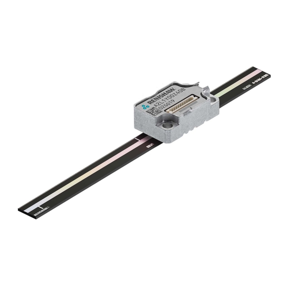
- Page 1 Installation guide M-9414-9446-01-A ATOM DX linear encoder systems RSLM high accuracy linear encoder ™...
-
Page 2: Table Of Contents
Contents Product compliance ATOM DX calibration overview Storage and handling System calibration ATOM DX system installation overview Restoring factory defaults RTLF tape scale: Enabling/disabling AGC Installation drawing Readhead LED diagnostics Application methods Troubleshooting Mounting (for lengths <500 mm only) Application ATOM DX (any length) Datum clamp... -
Page 3: Product Compliance
This device complies with part 15 of the FCC Rules. Operation is subject to the following two conditions: means without the written prior permission of Renishaw. The publication of material within this document does (1) This device may not cause harmful interference, and (2) this device must accept any interference not imply freedom from the patent rights of Renishaw plc. -
Page 4: Storage And Handling
Storage and handling RTLF and RCLC scales Scale and readhead N-heptane Propan-2-ol CHOHCH Minimum bend radius RTLF – 150 mm NOTE: Ensure self-adhesive tape is on the outside of bend. Storage Operating Humidity RCLC scale only +70 °C +70 °C −20 °C 0 °C 95% relative humidity... -
Page 5: Atom Dx System Installation Overview
/opticalencoders and 3D models at or contact your local Renishaw representative. For information on the ATOM DX product range refer to the ATOM DX data sheet L-9517-9736. IMPORTANT: Prior to installing readhead and scale, installation drawings should be reviewed to ensure correct orientation of readhead relative to scale. -
Page 6: Rtlf Tape Scale
Forward direction of readhead relative to scale Operating rideheight: 2.5 ±0.11 (40 µm version) 2.5 ±0.055 (20 µm version) Measuring length = Overall length − 3 mm For detailed installation drawings refer to www.renishaw.com /opticalencoders ATOM DX linear installation guide... -
Page 7: Application Methods
RTLF tape scale: Installation methods RTLF scale application depends upon scale length and bracket type RTLF tape scale Mounting Application (<500 mm only) (any length) Adjustable bracket Fixed mounting Readhead mounting is integral to the machine and does not allow rideheight adjustment. Ledge or dowel mounting Datum edge of readhead located against Datum edge of readhead mounted against machine axis. -
Page 8: Mounting (For Lengths <500 Mm Only)
If dowels or ledge are permanent, their maximum height above substrate is 0.6 mm. Support Clean scale using Renishaw scale cleaning wipes Install datum clamp, end covers and dowels (A-9523-4040) or a clean, dry, lint-free cloth. -
Page 9: Application (Any Length)
Fit readhead mounting bracket after removal of scale applicator. of the readhead. It can be used in conjunction with the Clean the scale using Renishaw scale wipes (A-9523-4040) ‘L’ mounting bracket (A-9402-0037) or a customer designed bracket. or a clean, dry, lint-free cloth. -
Page 10: Datum Clamp
RTLF: Datum clamp RTLF: Reference mark deselection The datum clamp (A-9585-0028) fixes the RTLF scale rigidly to the substrate at the location chosen. RTLF scale >100 mm in length has reference marks every 50 mm. Stickers can be used to deselect all The metrology of the system may be compromised if the datum clamp is not used. -
Page 11: Rclc Glass Spar Scale
Can be applied on one or both sides of the scale. 2.5 ±0.055 (20 µm version) Overall length L (mm) † Measuring length (mm) For detailed installation drawings refer to www.renishaw.com /opticalencoders † 20 µm pitch RCLC scale only. ATOM DX linear installation guide... -
Page 12: Mounting
After 24 hours when adhesive is cured, clean scale dowels be applied to one or both sides of the scale. using Renishaw scale wipes (A-9523-4040) or Ensure adhesive does not wick onto scale surface. a clean, dry, lint-free cloth. (End reference mark shown). -
Page 13: System Connection: Top Exit Readhead
P-clip are fitted with a P-clip to ensure appropriate cable strain relief. When using Renishaw’s top exit cables ensure that the P-clip is mounted within a 50mm radius of the readhead cable exit. Minimum static bend radius of cores is 3 mm. -
Page 14: Readhead Mounting And Alignment: Methods
There is a range of tools available to assist with readhead installation depending upon the system design and these are detailed below. For more details on designing the mounting bracket and selecting the appropriate mounting tools contact your local Renishaw representative. Ensure that the scale, readhead optical window and mounting face are clean and free from obstruction. -
Page 15: Shim Kit (A-9401-0050)
Check the readhead set-up LED is flashing surface is not scratched. Green along the full axis of travel. Renishaw offer a DTi adapter (A-9401-0105) that can be used to assist with this process. Proceed with ‘System calibration’ section (see page 17). -
Page 16: Dummy Head (A-9401-0072)
It is mounted in place of the readhead directly onto the bracket. The bracket should have a shoulder to control readhead yaw. Contact your local Renishaw representative for more information on bracket design. Mount the dummy head onto the bracket using 2 off M2 × 6 screws. -
Page 17: Accurate Bracket And Feeler Gauge
For more information on system tolerances refer to the installation drawings on www.renishaw.com /opticalencoders. For more information on bracket design contact your local Renishaw representative. 1 Mount the readhead onto the bracket using 2 off M2 × 6 screws. 2 Loosely mount the readhead bracket onto the axis. -
Page 18: Atom Dx Calibration Overview
For more details refer to the ‘Advanced Diagnostic Tool ADTi-100 and ADT View software quick start guide’ (M-6195-9321) and ‘Advanced Diagnostic Tool ADTi-100 and ADT View software user guide’ (M-6195-9413). † The software can be downloaded for free from www.renishaw.com /adt. ATOM DX... -
Page 19: System Calibration
NOTE: System calibration (CAL), restoring factory defaults and enabling/disabling AGC functions can also be carried out using the optional ADTi-100 and ADT View software. When re-installing the system, or in the case of continued calibration failure, factory defaults should be restored. www.renishaw.com /adt for more information. To restore factory defaults: Ensure signal strength has been optimised along the full axis of travel;... -
Page 20: Troubleshooting
Troubleshooting Fault Cause Possible solutions LED on the readhead is Blank There is no power to the readhead Check you have 5 V at the readhead For cable variants check correct wiring of connector LED on the readhead is Red and The signal strength is <50% Check the readhead optical window and scale are clean and free from contamination I can’t get a Green LED... - Page 21 Troubleshooting (continued) Fault Cause Possible solutions During calibration the LED on the The readhead is not seeing Ensure you are moving the readhead past your chosen reference mark several times readhead is double flashing Blue even a reference mark Check the scale/readhead orientation after moving it past the reference mark Check the scale readhead alignment several times...
-
Page 22: Cabled Readhead Dimensions
20.5 R>20 Dynamic bend radius R>10 Static bend radius 5 min Identification marks for readhead manufacture only. Notches will vary depending on readhead type. Not optical centreline www.renishaw.com /opticalencoders For detailed installation drawings refer to ATOM DX linear installation guide... -
Page 23: Top Exit Readhead Dimensions
Readhead / scale orientation 16.5 3 off mounting holes Ø2.5 min through 20.5 Identification marks for readhead manufacture only. Notches will vary depending on readhead type. Not optical centreline www.renishaw.com /opticalencoders For detailed installation drawings refer to ATOM DX linear installation guide... -
Page 24: Readhead Brackets Dimensions
ATOM readhead brackets dimensions Dimensions and tolerances in mm ‘ L’ mount bracket Side mount bracket (A-9402-0037) (A-9401-0103) 10.5 16.25 3 holes M2 × 0.4 Ø9.15 10.5 12.7 4.85 3 holes 8.25 M2 × 0.4 16.5 16.5 3.25 4 slot holes 2 holes Ø2.2 through M3 ×... -
Page 25: Output Signals
Output signals Cabled Top Exit 15 way D-type † ‡ 9 way D-type 15 way D-type 10 way JST 10 way JST Function Signal Colour alternative pin-out (H) Brown 7, 8 4, 12 Power White 2, 9 2, 10 − Blue Incremental Yellow... -
Page 26: Speed
Speed 20 µm encoder Maximum speed (m/s) * Minimum edge Clocked Readhead type separation * output option (MHz) (ns) (5 µm) (1 µm) (0.5 µm) (0.2 µm) (0.1 µm) (50 nm) (40 nm) (20 nm) (10 nm) (5 nm) (2.5 nm) 25.1 7.25 3.63... -
Page 27: Electrical Connections
Shield electronics IMPORTANT: The shield should be connected to the machine earth (Field Ground). 100R NOTE: For Renishaw top exit readhead cables the shield connection is provided by the P-clip. E− 100nF Maximum readhead cable length: 3 m Maximum extension cable length: Dependent on cable type, readhead cable length and clock speed. -
Page 28: Output Specifications
Output specifications Digital output signals Form – Square wave differential line driver to EIA RS422A Incremental * 2 channels A and B in quadrature (90° phase shifted) Signal period Resolution option P (μm) S (μm) Resolution code † † 0.05 Reference * 0.16 0.04... -
Page 29: General Specifications
40 µm version <±120 nm 20 µm ±3 µm A-9404-2xxx Renishaw encoder systems have been designed to the relevant EMC standards but must be correctly 40 µm ±3 µm A-9404-4xxx integrated to achieve EMC compliance. In particular, attention to shielding arrangements is essential. - Page 30 © 2017-2019 Renishaw plc. All rights reserved. Renishaw reserves the right to change specifications without notice. RENISHAW and the probe symbol used in the RENISHAW logo are registered trade marks of Renishaw plc in the United Kingdom and other countries. Part no.: M-9414-9446-01-A apply innovation and names and designations of other Renishaw products and technologies are trade marks of Renishaw plc or its subsidiaries.
Need help?
Do you have a question about the ATOM DX Series and is the answer not in the manual?
Questions and answers