Renishaw QUANTiC RESM40 Installation Manual
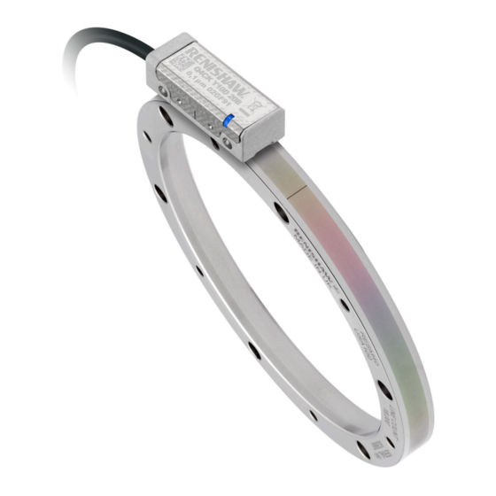
Angle encoder system
Hide thumbs
Also See for QUANTiC RESM40:
- Installation manual (19 pages) ,
- Installation manual (25 pages)

Related Manuals for Renishaw QUANTiC RESM40


Summary of Contents for Renishaw QUANTiC RESM40
- Page 1 Installation guide M-9417-9201-03-A QUANTiC RESM40 angle encoder system ™ Image here if required www.renishaw.com/quanticdownloads #renishaw...
- Page 2 This page is intentionally left blank. QUANTiC RESM40 angle encoder system installation guide...
-
Page 3: Table Of Contents
RESM40 ring specifications ......................39 www.renishaw.com... -
Page 4: Legal Notices
Renishaw office. 47 CFR Section 15.21 Renishaw warrants its equipment and software for a limited period (as set out in the Standard Terms and Conditions), provided that they are installed and used exactly as defined in associated The user is cautioned that any changes or modifications not expressly approved by Renishaw plc Renishaw documentation. - Page 5 ADTi-100 data sheet (Renishaw part no. L-9517-9699), Advanced Diagnostic Tool ADTi-100 and Renishaw Inc. ADT View software user guide (Renishaw part no. M-6195-9413) and Advanced Diagnostic Tool 1001 Wesemann Drive ADTi-100 and ADT View software quick-start guide (Renishaw part no. M-6195-9321). These...
- Page 6 Disposal of waste electrical and electronic equipment The use of this symbol on Renishaw products and/or accompanying documentation indicates that the product should not be mixed with general household waste upon disposal. It is the responsibility of the end user to dispose of this product at a designated collection point for waste electrical and electronic equipment (WEEE) to enable reuse or recycling.
- Page 7 PROFITS; OR BUSINESS INTERRUPTION) HOWEVER CAUSED AND ON ANY THEORY OF LIABILITY, WHETHER IN CONTRACT, STRICT LIABILITY, OR TORT (INCLUDING NEGLIGENCE OR OTHERWISE) ARISING IN ANY WAY OUT OF THE USE OF THIS SOFTWARE, EVEN IF ADVISED OF THE POSSIBILITY OF SUCH DAMAGE. www.renishaw.com...
- Page 8 Renishaw and the United States Government, civilian federal agency or prime contractor respectively. Please consult the applicable contract or subcontract and the software licence incorporated therein, if applicable, to determine your exact rights regarding use, reproduction and/or disclosure.
-
Page 9: Storage And Handling
QUANTiC non-contact optical encoder systems provide good immunity against contaminants such as dust, fingerprints and light oils. However, in harsh environments such as machine tool applications, protection should be provided to prevent ingress of coolant or oil. Ring and readhead Ring only Readhead only Propan-2-ol N-heptane Acetone Acetone Chlorinated Methylated Chlorinated Methylated CHOHCH COCH COCH Solvents Spirits Solvents Spirits www.renishaw.com... - Page 10 Temperature Humidity 95% relative humidity (non-condensing) to IEC 60068-2-78 Storage System −20 °C to +70 °C Operating System 0 °C to +70 °C QUANTiC RESM40 angle encoder system installation guide...
-
Page 11: Quantic Readhead Installation Drawing
Forward direction of ring (increasing count) Calibration rideheight: 2.1 ±0.15 Operating rideheight: 2.1 ±0.2 Extent of mounting faces. The recommended thread engagement is 5 mm minimum (7.5 mm including counterbore) and the recommended tightening torque is between 0.25 Nm and 0.4 Nm. www.renishaw.com... -
Page 12: Resm40 'A' Section Ring Installation Drawing
N holes equally spaced on PCD ØDH M3 × 0.5 through c/bore top face Ø3.5 × 4 deep 0.5 × 45° 15° ±0.2° θ 1 × 45° ØDI ØDH ØDO Refer to ‘RESA30 ‘A’ section ring dimensions’ on page for dimension and hole information. QUANTiC RESM40 angle encoder system installation guide... - Page 13 350.20 330.00 412.70 392.08 32 400 10° 412.30 392.00 417.40 380.10 32 768 10° 417.00 380.00 489.12 451.10 38 400 18° 488.72 450.90 550.20 510.10 43 200 9° 549.80 510.00 There are no tapped holes on the 489 mm ring. www.renishaw.com...
-
Page 14: Resm40 'B' Section Ring Installation Drawing
15° 200.20 180.00 Section A–A 2.5 × 45° NOTE: θ is the angle between one tapped hole and the adjacent clearance hole. The angle between two clearance holes is 2θ. R0.5 ØDI ØDH ØDO QUANTiC RESM40 angle encoder system installation guide... -
Page 15: Resm40 Ring Mounting Options
Enables simplest adjustment. • Will not correct eccentricity of the supporting shaft • Offers highest accuracy. Notes • Enables eccentricity to be compensated. • Offers excellent mechanical stability against thermal cycling, shock and vibration. • Minimises cost of substrate preparation. www.renishaw.com... -
Page 16: Taper Mounting The Resm40 'A' Section Ring
Dial Test Indicator (DTI) with a ruby ball stylus • Appropriate cleaning solvents (see ‘Storage and handling’ on page 9) • Hex key • Torque wrench Optional parts: • Renishaw scale wipes (A-9523-4040) • Lint-free cloth QUANTiC RESM40 angle encoder system installation guide... -
Page 17: Mounting Shaft Specifications
DO = Nominal external diameter. Diameter (mm) Roundness value (mm TIR) ≤ 115 0.0125 Recommended surface finish ≤ Ra 1.2. 150 to 225 0.025 NOTE: It is recommended that the mounting surface is a turned, rather than ground finish. ≥ 300 0.0375 www.renishaw.com... -
Page 18: Mounting The Ring
NOTES: • It may be necessary to loosen some screws whilst tightening other screws. • At this stage, the screws should only be lightly tightened (less than 0.5 Nm) to allow further final adjustment. QUANTiC RESM40 angle encoder system installation guide... - Page 19 • For RESM40 rings with 6, 9 or 12 mounting holes, insert all the remaining M3 screws. 18. Clean the ring using Renishaw scale wipes or a clean, dry, lint-free cloth. • For RESM40 rings with 16 mounting holes, insert 4 equally spaced M3 screws.
-
Page 20: Interference Fit Mounting The Resm40 'A' Section And Resm40 'B' Section Rings
NOTE: Recommended screw type M3 × 0.5: ISO 4762 / DIN 912 grade 10.9 minimum /ANSI B18.3.1M. • Appropriate cleaning solvents (see ‘Storage and handling’ on page 9) • Hex key • Torque wrench Optional parts: • Renishaw scale wipes (A-9523-4040) • Lint-free cloth QUANTiC RESM40 angle encoder system installation guide... -
Page 21: Mounting The Ring
5. Tighten all of the screws. 130.052 392.073 130.027 392.037 6. Clean the ring using Renishaw scale wipes or a clean, dry, lint-free cloth. 145.052 145.027 NOTES: Ensure that all of the screws are tightened to 1.6 Nm. The recommended thread engagement is 6 mm. -
Page 22: Quantic Readhead Quick-Start Guide
26) and repeat the installation and calibration routine. For more details refer to the Advanced Diagnostic Tool ADTi-100 and ADT View software user guide (Renishaw part no. M-6195-9413) and Advanced Diagnostic Tool ADTi-100 and ADT View software quick-start guide (Renishaw part no. -
Page 23: Readhead Mounting And Alignment
The optional Advanced Diagnostic Tool ADTi-100 (A-6195-0100) and ADT View software can be used to optimise signal strength in challenging installations. See www.renishaw.com/adt for more information. Readhead set-up LED status NOTE: For full readhead LED diagnostics, see ‘Readhead LED diagnostics’... - Page 24 ‘Renishaw’ logo within ±0.5 mm. No external actuators or physical adjustment are required. QUANTiC RESM40 angle encoder system installation guide...
-
Page 25: System Calibration
Reference mark phasing NOTE: The functions described below can also be carried out by using the optional ADTi-100 and ADT View software. See www.renishaw.com/adt for more information. 1. Move the readhead back and forth over the reference mark until the LED stops flashing and remains solid blue. -
Page 26: Restoring Factory Defaults
The AGC is automatically enabled once the system has been calibrated (indicated by a blue LED). AGC can be manually switched off by connecting the ‘Remote CAL’ output pin to 0 V for > 3 seconds < 10 seconds. The LED will be solid green. NOTE: AGC can be switched on or off using the optional ADTi-100 and ADT View software. See www.renishaw.com/adt for more information. QUANTiC RESM40 angle encoder system installation guide... -
Page 27: Troubleshooting
Realign the readhead to obtain a green flashing LED at the mid-point of the run-out • Recalibrate the system (see page 25) Can’t initiate the calibration routine Signal size is < 70% • Realign the readhead to obtain a green flashing LED www.renishaw.com... - Page 28 Clean the scale and readhead optical window and check for damage, then recalibrate the system, ensuring all the incremental signal calibration steps and the reference mark phasing steps are completed (see page 25) QUANTiC RESM40 angle encoder system installation guide...
- Page 29 When using with ADTi-100 in stand-alone mode, ensure the Termination tool is connected (A-6195-2132) Incorrect termination (analogue variant only) • Exit the CAL mode and restore factory defaults (see page 25) • Check the readhead set-up and alignment (see page 23) www.renishaw.com...
-
Page 30: Output Signals
Green Violet Reference mark − Grey Pink Limits Black Alarm − Orange Remote CAL Clear Shield Screen Case Case Case Case Ferrule The remote CAL line must be connected for use with ADTi-100. QUANTiC RESM40 angle encoder system installation guide... - Page 31 2, 10 Cosine − Blue Incremental Yellow Sine − Green Violet Reference mark − Grey Pink Limits Black Setup Clear Remote CAL Orange Shield Screen Case Case Ferrule The remote CAL line must be connected for use with ADTi-100. www.renishaw.com...
- Page 32 14-way JST connector (termination code J) 12-way circular Binder mating socket (A-6195-0105). Pack of 5 14-way JST SH mating sockets: Bottom mount (A-9417-0025) Side mount (A-9417-0026) Maximum of 20 insertion cycles for JST connector. QUANTiC RESM40 angle encoder system installation guide...
-
Page 33: Speed
V × 1000 × 60 Where V = maximum linear speed (m/s) and D = external diameter of RESM40 ring (mm) π D For a readhead with a 1 m cable. If the speed exceeds 20 m/s, SDE performance cannot be guaranteed. www.renishaw.com... -
Page 34: Electrical Connections
Readhead cable Dependent on cable type, readhead cable length and clocked output option. Maximum extension cable length Contact your local Renishaw representative for more information. Readhead to ADTi-100 Remote CAL operation Remote operation of the CAL /AGC is possible via CAL signal. - Page 35 5 V to 24 V Single-ended alarm signal termination (not available with ‘A’ cable termination) NOTE: Select R so that maximum current does not exceed 20 mA. Alternatively, use a suitable Customer relay or opto-isolator. Readhead electronics 100R E− 100nF www.renishaw.com...
-
Page 36: Output Specifications
NOTE: A wide reference mark option, outputting a reference pulse for the duration of the signal • The readhead speed is too high for reliable operation period is available. Contact your local Renishaw representative for more information. or 3-state alarm Differentially transmitted signals forced open circuit for > 15 ms when alarm conditions valid. - Page 37 Between 50% and 70% signal level, V is a duty cycle. Time spent at 3.3 V increases with incremental signal level. At > 70% signal level V is nominal 3.3 V. The set-up signal as shown is not present during the calibration routine. www.renishaw.com...
-
Page 38: General Specifications
Rotary ≤ ∅135 mm < ±120 nm < ±80 nm CAUTION: Renishaw encoder systems have been designed to the relevant EMC standards, but must be correctly integrated to achieve EMC compliance. In particular, attention to shielding arrangements is essential. QUANTiC RESM40 angle encoder system installation guide... -
Page 39: Resm40 Ring Specifications
RESM40 ring specifications Pitch 40 μm Material 303 / 304 stainless steel Coefficient of thermal expansion (at 20 °C) 15.5 ±0.5 µm/m/°C www.renishaw.com... - Page 40 +44 (0) 1453 524524 uk@renishaw.com © 2017–2021 Renishaw plc. All rights reserved. This document may not be copied or reproduced in whole or in part, or transferred to any other WHILE CONSIDERABLE EFFORT WAS MADE TO VERIFY THE ACCURACY OF THIS media or language by any means, without the prior written permission of Renishaw.
Need help?
Do you have a question about the QUANTiC RESM40 and is the answer not in the manual?
Questions and answers