
Related Manuals for Renishaw T101


Summary of Contents for Renishaw T101
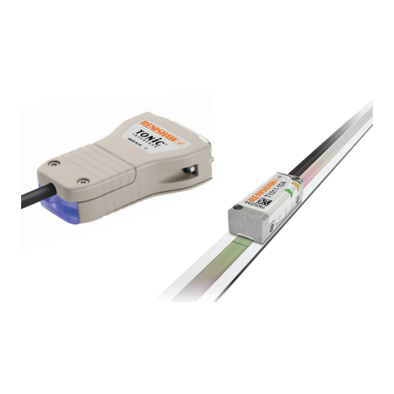
- Page 1 Installation guide M-9653-9225-05-C TONiC T101 RSLM / RELM high accuracy linear encoder system RSLM high accuracy linear encoder ™...
-
Page 2: Table Of Contents
Contents Product compliance Storage and handling TONiC readhead installation drawing Measuring lengths Adhesive mounting installation drawing Adhesive mounting installation Clip/clamp mounting installation drawing Clip/clamp mounting installation TONiC interface drawing TONiC quick-start guide System connection Readhead mounting and alignment Reference mark selector and limit magnet installation System calibration Output signals Speed... -
Page 3: Product Compliance
Correct disposal of this product will help to save valuable resources and prevent or transferred to any other media or language, by any means without the written prior permission of Renishaw. potential negative effects on the environment. For more information, please contact your local waste disposal The publication of material within this document does not imply freedom from the patent rights of Renishaw plc. -
Page 4: Storage And Handling
Storage and handling Scale and readhead Scale only Readhead only N-heptane Acetone Acetone Chlorinated Chlorinated COCH COCH Solvents Solvents Propan-2-ol Methylated Methylated CHOHCH Spirits Spirits Storage Operating Humidity +70 °C 0 °C Minimum bend radius RSLM – 250 mm +70 °C RELM –... -
Page 5: Tonic Readhead Installation Drawing
TONiC T101 readhead installation drawing Dimensions and tolerances in mm Forward direction of Reference mark selector readhead relative to scale (A-9653-0143) Only required for (Roll tol. ±0.5°) (Yaw tol. ±0.4°) T1010 readheads 15 ±1 0.08 0.25 (Dimensions as P limit) 8.75*... -
Page 6: Measuring Lengths
Measuring lengths Dimensions and tolerances in mm 1.5 (Clip/clamp mounting) RSLM 1.6 (Clip/clamp mounting) RELM 1.7 (Adhesive mounting) RSLM 1.8 (Adhesive mounting) RELM Measuring length, ML = (L-25) with dual 10 mm limits 17.5 ML = (L-10) without limits 0.05 F = axis of motion Ra 3.2 2.1 ±0.15... -
Page 7: Adhesive Mounting Installation Drawing
Adhesive mounting installation drawing Dimensions and tolerances in mm 0.05/50 Datum edge ‡ 14.9 ±0.2 Alignment dowels, maximum spacing 350 F = axis of motion RSLM Use with T1011 readhead (Centre reference mark) L 4 m: L/2 ±0.5 L 4 m: L/2 ±2 Reference mark position RSLE Option A reference mark position... -
Page 8: Adhesive Mounting Installation
Locate scale against dowels or ledge and rotate down onto substrate. Press down with firm finger pressure. Mounting ledge Allow 24 hours for epoxy to cure fully, then clean scale using Renishaw scale wipes (A-9523-4040) or a clean, dry, lint-free cloth. TONiC RSLM/RELM installation guide... -
Page 9: Clip/Clamp Mounting Installation Drawing
Clip/clamp mounting installation drawing Dimensions and tolerances in mm Datum clamp L 4 m: L/2 ±0.5 4 m: L/2 ±2 (A-9584-2050) Special M3 low-profile (clamp height) screw with 1.5 mm Reference mark 14.9 ±0.2 Datum edge position hex socket. 6.75 0.05/50 (A-9584-2047 pack of 25) RSLM... -
Page 10: Clip/Clamp Mounting Installation
Only the special low-profile screws supplied with the clips should be used. lint-free cloth. Additional screws can be purchased from Renishaw (A-9584-2047 pack of 25). NOTE: When mounting scale to vertical surfaces, temporary bridge clamps (A-9584-2112) are available which support the scale prior to fitting clips. -
Page 11: Tonic Interface Drawing
TONiC interface drawing TONiC quick-start guide Dimensions and tolerances in mm This section is a quick-start guide to installing a TONiC system. More detailed information on installing the system is contained in the following sections of the Installation guide. INSTALLATION Ensure scale, readhead optical window and mounting faces are clean and free from obstructions. -
Page 12: System Connection
System connection Disconnecting the readhead Approved ESD precautions must be followed at all times during readhead and interface electrical Remove the cover plate on the interface connections. The readhead is connected to the (2 x M2.5 hex head screws). Ti/TD interface via a small, rugged connector to allow for easy feed-through during installation. -
Page 13: Readhead Mounting And Alignment
Readhead mounting and alignment Reference mark selector and limit magnet installation Mounting bracket For accuracy and ease of positioning of reference mark selector and limit magnets, the applicator tool (A-9653-0201) should be used. The magnet should be attached to the applicator tool as shown below. The bracket must have a flat mounting surface and should provide adjustment to enable Limit magnets can be positioned at any user defined location along the scale, but the reference mark selector magnet conformance to the installation tolerances, allow adjustment to the rideheight of the readhead,... -
Page 14: System Calibration
TD interface can be calibrated in either resolution. NOTE: The system must be calibrated before switching AGC on. Step 1 – Incremental signal calibration Ensure Automatic Gain Control is switched off T101 readhead LED diagnostics (CAL LED on readhead is not illuminated) before beginning calibration. Indication... -
Page 15: Output Signals
Output signals Interface Interface output (digital) Ti0004 to Ti20KD Interface Interface output (analogue) Ti0000 only and TD4000 to TD0040 Ti0000 Ti0004 - Ti20KD TD4000 - TD0040 Function Output type Signal Function Output type Signal Power 5 V Power Power 7, 8 7, 8 5 V Sense 2, 9... -
Page 16: Electrical Connections
Electrical connections TONiC grounding and shielding Analogue outputs Customer Extension cable max. electronics 50 m dependent upon Ti/TD interface Readhead Inner shield output frequency 120R Output signals Outer shield Limit output ( No limits on TD interfaces IMPORTANT: The outer shield should be connected to the machine earth (Field Ground). The inner shield should be connected to 0 V at receiving electronics only. -
Page 17: Output Specifications
NOTE: Select ‘standard’ or ‘wide’ reference at time of ordering, to match the requirements of the controller being used. Wide reference mark not available on Ti0004 interfaces. Limits Open collector output, asynchronous pulse Limits Open collector output, asynchronous pulse Digital Ti interfaces only Ti0000 interface only T101 readhead only Active high Active low Active high Active low... -
Page 18: General Specifications
(m) 40 to 50 <40 analogue Renishaw encoder systems have been designed to the relevant EMC standards, but must be correctly integrated to achieve EMC compliance. In particular, attention to shielding arrangements is essential. TONiC RSLM/RELM installation guide... - Page 19 RENISHAW ® and the probe symbol used in the RENISHAW logo are registered trade marks of Renishaw plc in the United Kingdom and other countries. *M-9653-9225-05* apply innovation and names and designations of other Renishaw products and technologies are trade marks of Renishaw plc or its subsidiaries.
Need help?
Do you have a question about the T101 and is the answer not in the manual?
Questions and answers